1. Introduction
The flow field around a wind turbine is often modeled as a steady, uniform, axial wind. In reality, the flow around a turbine blade is a more complex process that includes misalignments, wind shear, turbulence and dynamic winds. For a floating offshore horizontal axis wind turbine (HAWT), this process becomes more complex than for an onshore or fixed offshore system. Because of the motion of floating wind turbine, which includes three translational components (heavy in the vertical, sway in the lateral and surge in the axial) and rotational components (yaw about the vertical axis, pitch about the lateral, and roll about the axial) as shown in
Figure 1, the additional effect of the contribution of a wind is accounted for in the turbine system. In those motions, platform pitching and yawing motion primarily lead to a non-uniform or skewed flow on a rotor turbine and may cause significant effects on the flow field around the rotor blade [
1,
2,
3,
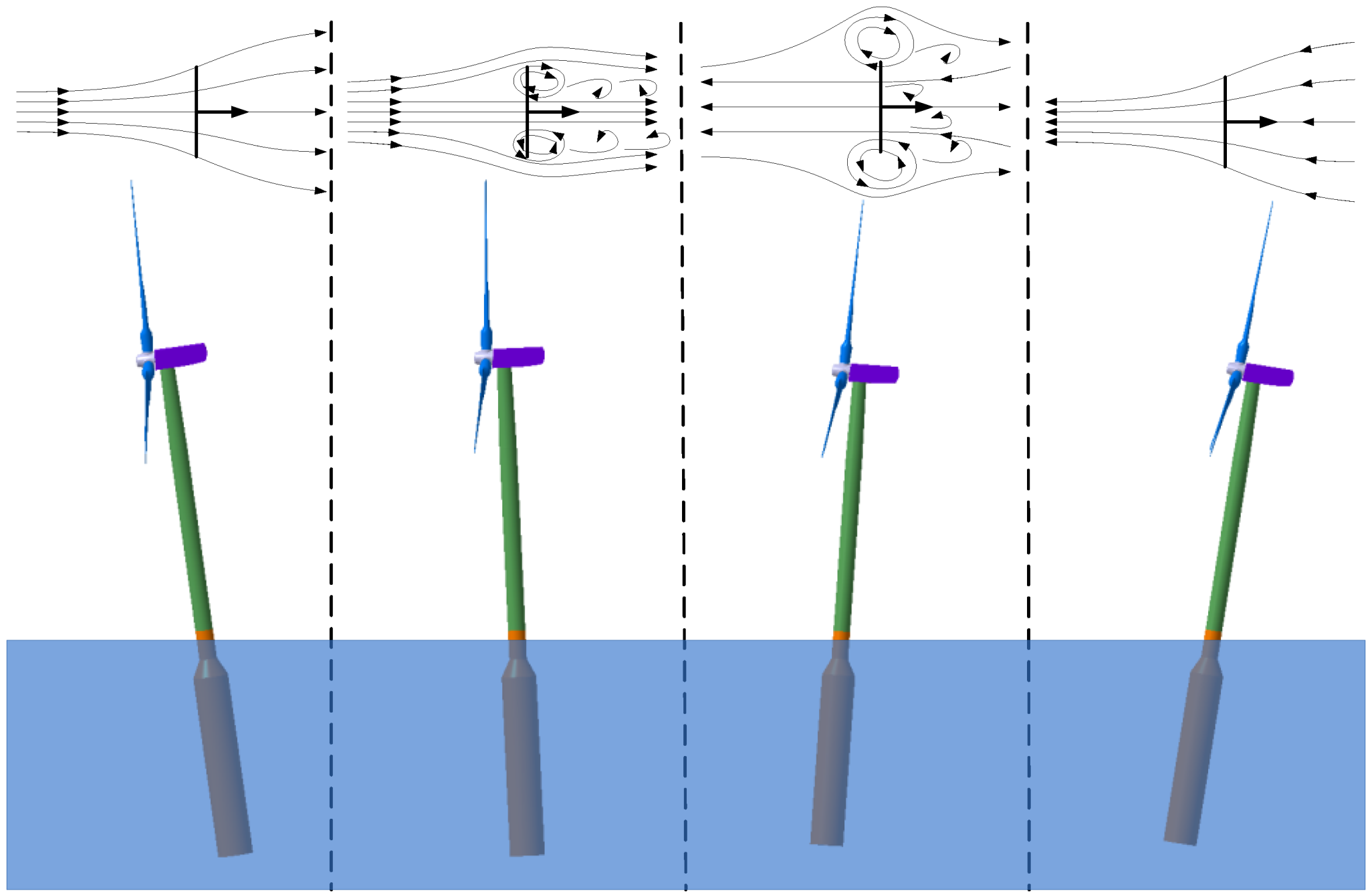
4]. As an example, a typical floating HAWT (
Figure 2, from left to right) shows a flow field around a rotor blade during spar-buoy pitching. As the rotor blade begins to pitch back, it interacts with its own wake which develops turbulence region. At several points, a toroidal recirculation is generated that flows normal to the rotor blade. This transitional aerodynamic phenomenon is called the vortex ring state, or settling with power [
5]. The pitching motion intermediately causes a transient flow condition which is one of the potential operating and the simulation problems for a floating wind turbine. In particular, the pitching and yawing motion may cause more power in a floating offshore HAWT system because of the above issues [
4,
6,
7].
Figure 1.
Degrees of freedom for an offshore floating wind turbine platform.
Figure 1.
Degrees of freedom for an offshore floating wind turbine platform.
The major objective of the present work is to show the different predictions among traditional blade element momentum, general dynamic wake and advanced computational fluid dynamics approach for a floating offshore wind turbine (FOWT). In this study, Phase IV of the IEA Annex XXIII Offshore Code Comparison Collaboration (OC3) [
8], which considered the spar-buoy concept, was chosen to show the critical effects of unsteady aerodynamic loads because of platform motion. The computational fluid dynamics (CFD) analysis of a three-dimensional unsteady flow analysis of a 5-MW floating offshore wind turbine was performed to consider the effects of the pitching degrees of freedom (DOF) motion of the support platform. Using computational fluid dynamics, the Reynolds Averaged Navier-Stokes equation with the shear-stress transport (SST)
k-ω turbulence model was applied. This model has the potential to provide consistent and physical simulations of the complex flow field around a wind turbine blade [
9,
10,
11]. The meshes are used to discretize a computational domain that contains several different meshes that overlap each other in an arbitrary manner. Rigid Body Motion (RBM) was used to model the rotor blades in which the computational domain is changing with time because of motion on the blade surface boundaries. The superposing motions technique that allows you to add more rigid rotations to translation and rotation motions was applied herein. In the present study, blade rotation motion was added to the platform pitching motion that was defined as a sine function. Superposing motion can be simultaneously applied for one or more arbitrary motions. The current results are also compared to a developed in-house code based on the unsteady blade element momentum (UBEM) theory with the direct local relative velocity method (DLRM) that was constructed in a previous study [
12]. We also proposed the equivalent averaged velocity method (EqAM) that can simplifies the relative velocity calculations on a rotating blade due to the platform pitching motion as the relative velocity at a hub instead of calculating the direct local velocity at each blade segment. Using EqAM, both in-house UBEM and FAST (Fatigue, Aerodynamics, Structures, and Turbulence) code with AeroDyn module of routines developed by the National Renewable Energy Laboratory (NREL) were applied to evaluate the accuracy of results. This in-house code performed well for a NREL 5-MW baseline wind turbine [
13]. It can be concluded that three approaches, including CFD, UBEM, and FAST, displayed good correlations in the unsteady aerodynamic analysis of a FOWT undergoing periodic pitching.
Figure 2.
Platform pitching motion and its effects on the surrounding flow-field.
Figure 2.
Platform pitching motion and its effects on the surrounding flow-field.
4. Results and Discussion
In this study, the unsteady simulation has performed using a computational fluid dynamic with multiple reference frames (CFD-MRF) model. This approach was conducted using the commercial ANSYS FLUENT version 14.0 software [
13]. The Multiple Reference Frames (MRF) approach was applied to define the virtual blade rotation about its axis whereas the dynamic mesh and remeshing technique was used to prescribe the pitching motion of the floating platform. On the contrary, the computational fluid dynamic with rigid body motion (CFD–RBM) approach was applied to define the real blade rotation. Using the CFD-RBM approach, the flow unsteadiness due to wakes among wind turbine blades can be taken into account. To impose the pitching motion of the floating platform, a superimposing motion was also used in the commercial STAR-CCM+ software package.
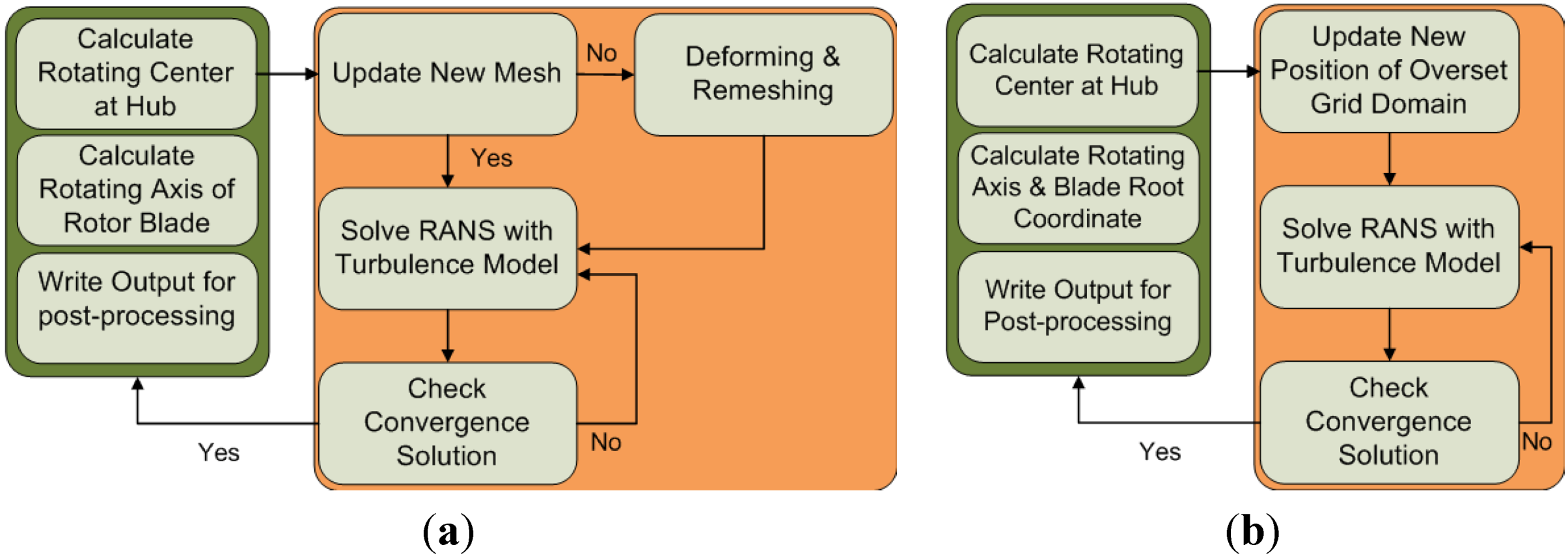
Figure 5 shows a computational road map using both the unsteady CFD-MRF and CFD-RBM approaches. The right hand side blocks of each road map indicate that the unsteady computational simulation was solved by the commercial solvers, whereas other computational blocks are developed by user-defined functions that were simultaneously incorporated in the commercial software. The main purpose of user-defined functions is to calculate the rotating center and rotating axis of wind turbine blades. Additionally, the axis vectors of the blade coordinate system were also calculated using the standard 3-2-1 Euler angle so that the force components on each blade root were estimated during the unsteady CFD simulation.
Figure 5.
Computational flowchart for computational fluid dynamic (CFD) approaches. (a) Computational fluid dynamic with multiple reference frames (CFD-MRF); and (b) Computational fluid dynamic with rigid body motion (CFD-RBM).
Figure 5.
Computational flowchart for computational fluid dynamic (CFD) approaches. (a) Computational fluid dynamic with multiple reference frames (CFD-MRF); and (b) Computational fluid dynamic with rigid body motion (CFD-RBM).
Generally, numerical solutions obtained by the CFD technique can be somewhat different depending on the discretization resolution of the computational domain. By limiting a maximum and minimum size of the elements on a wind turbine blade in
Table 1, further refinement of the mesh over the computational domain was achieved in the present study. In order to show the numerical convergence of the present solution, the aerodynamic power and thrust over a range of an amount of elements are compared with those by the FAST code considering both blade element momentum (BEM) and generalized dynamic wake (GDW) models. As shown in
Figure 6, the present CFD-RBM results show overall good correlations with those obtained by the FAST code.
Figure 6.
Mesh convergence study for the grid size on NREL 5-MW wind turbine surface. (a) Aerodynamic Power; and (b) Aerodynamic Thrust.
Figure 6.
Mesh convergence study for the grid size on NREL 5-MW wind turbine surface. (a) Aerodynamic Power; and (b) Aerodynamic Thrust.
The present CFD approach tends to somewhat under predict since the mesh quality of the CFD method is very fine compared to the FAST code approach. It can be found that there are about 2.6% and 6.9% differences in the predicted aerodynamic thrust and power between the present CFD method and the FAST code, respectively, whereas, differences of aerodynamic power and thrust between FAST with BEM and GDW are about 4.7% and 2.7%, respectively. Based on this mesh convergence test and fundamental comparisons we conducted more high level computations considering the pitching motion of a FOWT model. It should be emphasized here that flow unsteadiness for the condition of pitching motion for rotating blades must be higher than that of the previous comparison case. Thus, the computational grid of case 3 in
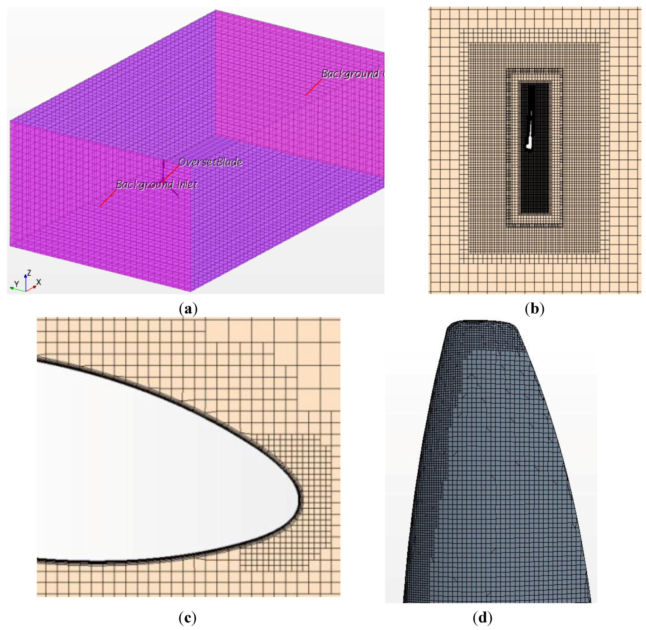
Table 1 is chosen for the unsteady simulation of rotating wind turbine blades with platform pitching motion in order to accurately capture complex wake effect behind the rotating blades. The refinement grid on a part of the trailing edge of wind turbine blade can be seen in
Figure 3d.
Figure 7 and
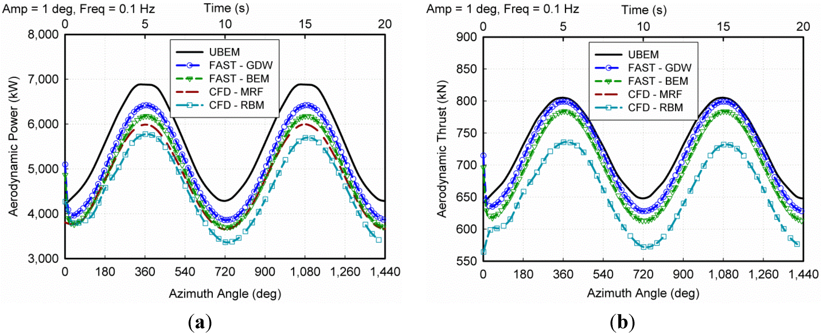
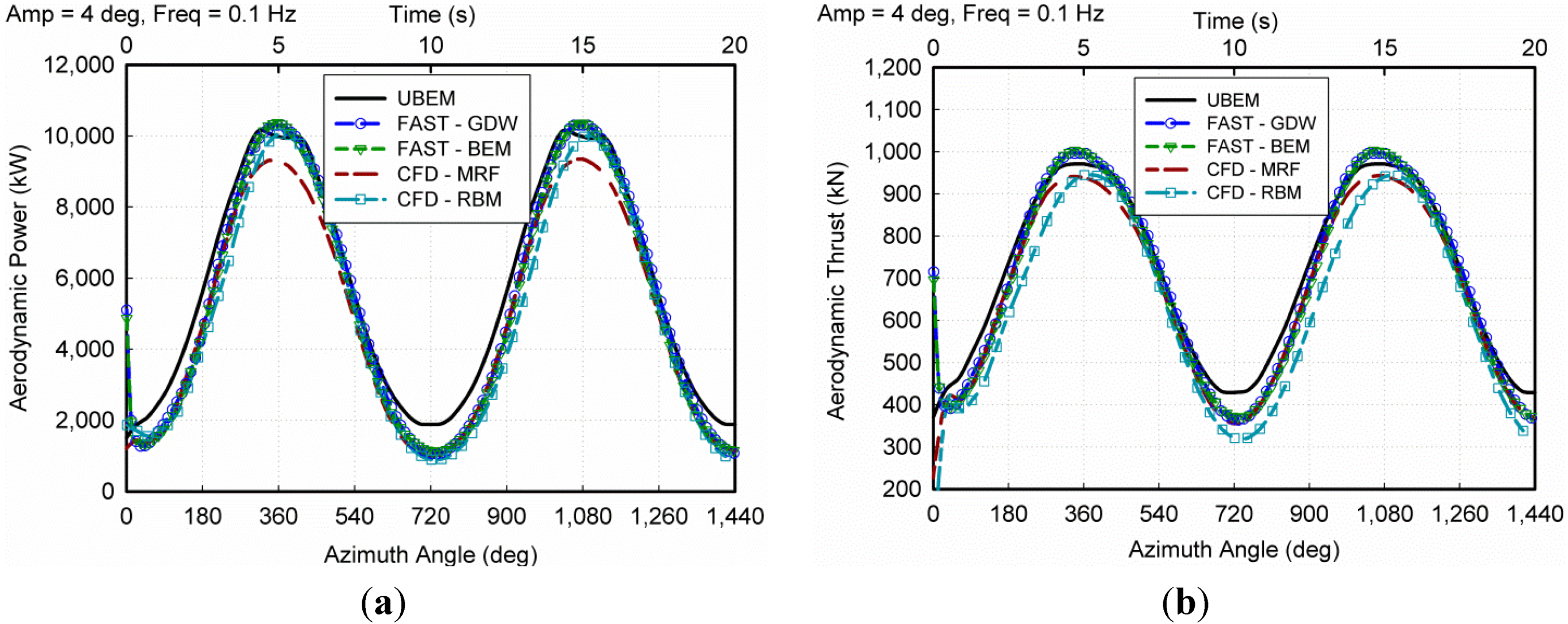
Figure 8 show the comparison of the unsteady aerodynamic power and thrust responses among the CFD, UBEM and FAST solvers for the pitching motion with a frequency (Freq) of 0.1 Hz and the amplitude (Amp) of 1° and 4°. These frequencies and amplitudes for the pitching motion may exist under normal wind and wave conditions experienced by the floating wind turbine. The aerodynamic power and thrust respond as a sine function.
Figure 7 and
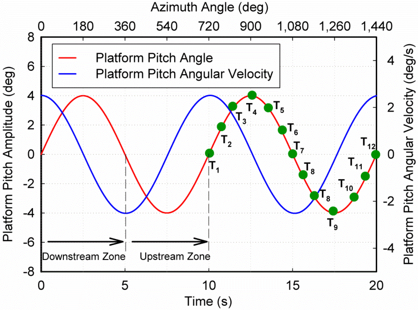
Figure 8 show that the predicted aerodynamic responses are similar to the frequency of the pitching motion of a FOWT which periodically moves with a frequency of 0.1 Hz. For the initial platform pitching motion, a numerical error exists because of quickly changing wind conditions. After this initial time, the dynamic responses regularize in all of the considered numerical approaches. During the 1/4
T and 3/4
T period of the pitching motion, the angular velocity decreases as shown in
Figure 4. Therefore, this lower angular velocity decreases the contribution of additional velocity on a given rotor blade and increases the non-axial angle of the wind turbine. By contrast, during the 2/4
T and 4/4
T time of the pitching motion, additional velocity contributions tend to increase, whereas the non-axial (yaw/pitch) angle error decreases. The decrease and increase of the additional velocity contribution and non-axial angle are present in both the downstream and upstream regimes of the rotor blade. As shown in
Figure 7 and
Figure 8, increasing the additional velocity contribution and decreasing the non-axial angle increase the aerodynamic power and thrust for the 1/4
T time of pitching motion. However, this response reverses during the 3/4
T time. The wind turbine blades substantially move in the wake regime (downstream) during the 1/4
T time whereas there exists a wake zone during the 3/4
T time. Alteration in the additional velocity contribution and the strong interaction between the rotor blade and wake regime significantly affect the aerodynamic performance of a wind turbine. During the 1/4
T time, the aerodynamic power and thrust tend to increase because of increases on the additional velocity contribution and the strong interaction between the rotor blades and wake regime. However, a similar behavior is not exhibited during the 4/4
T time while additional velocity contribution decreases and strong interaction between rotor blades and wake regime remains. Therefore, increasing the additional velocity contribution (and not wake interference) significantly affects the performance during the 1/4
T time, and the reverse is true during the 4/4
T time. For weak wake interactions between the rotor blades and its wake during the 2/4
T and 3/4
T time, the additional velocity contribution and non-axial angle maintain a key role in the aerodynamic performance. The increasing or decreasing in additional velocity contribution increases or decreases the aerodynamic thrust and power, respectively.
As shown in
Figure 7 and
Figure 8, the current numerical approaches predicted a good trend for the aerodynamic power and thrust of a FOWT under pitching conditions. The UBEM approach over-predicted these values more than the other approaches. The FAST with BEM tends to underestimate the aerodynamic power and thrust compared to the FAST with GDW, especially the peak area of additional velocity contribution as shown in
Figure 9. The results obtained by the CFD-RBM approach displays a difference in the maximum peak area in which the pitching motion achieves a maximum motion velocity. Additionally, the maximum power occurs at a 4° motion amplitude. At that amplitude, the relative wind velocity contribution also achieves a maximum magnitude. The UBEM code did not account for the effects of wake interference between the rotor blade and windmill in present study, whereas FAST solver can account for wake dynamics, particularly the GDW aerodynamic theory. Both the axial and tangential induction factor will be simultaneously applied by the AeroDyn of FAST solver.
Figure 7.
Unsteady aerodynamic comparison using the UBEM, CFD and FAST (NREL) methods for a platform pitching motion with an amplitude of 1° and a frequency of 0.1 Hz. (a) Aerodynamic Power; and (b) Aerodynamic Thrust.
Figure 7.
Unsteady aerodynamic comparison using the UBEM, CFD and FAST (NREL) methods for a platform pitching motion with an amplitude of 1° and a frequency of 0.1 Hz. (a) Aerodynamic Power; and (b) Aerodynamic Thrust.
Figure 8.
Unsteady aerodynamic comparison using the UBEM, CFD and FAST (NREL) methods for a platform pitching motion with an amplitude of 4° and a frequency of 0.1 Hz. (a) Aerodynamic Power; (b) Aerodynamic Thrust.
Figure 8.
Unsteady aerodynamic comparison using the UBEM, CFD and FAST (NREL) methods for a platform pitching motion with an amplitude of 4° and a frequency of 0.1 Hz. (a) Aerodynamic Power; (b) Aerodynamic Thrust.
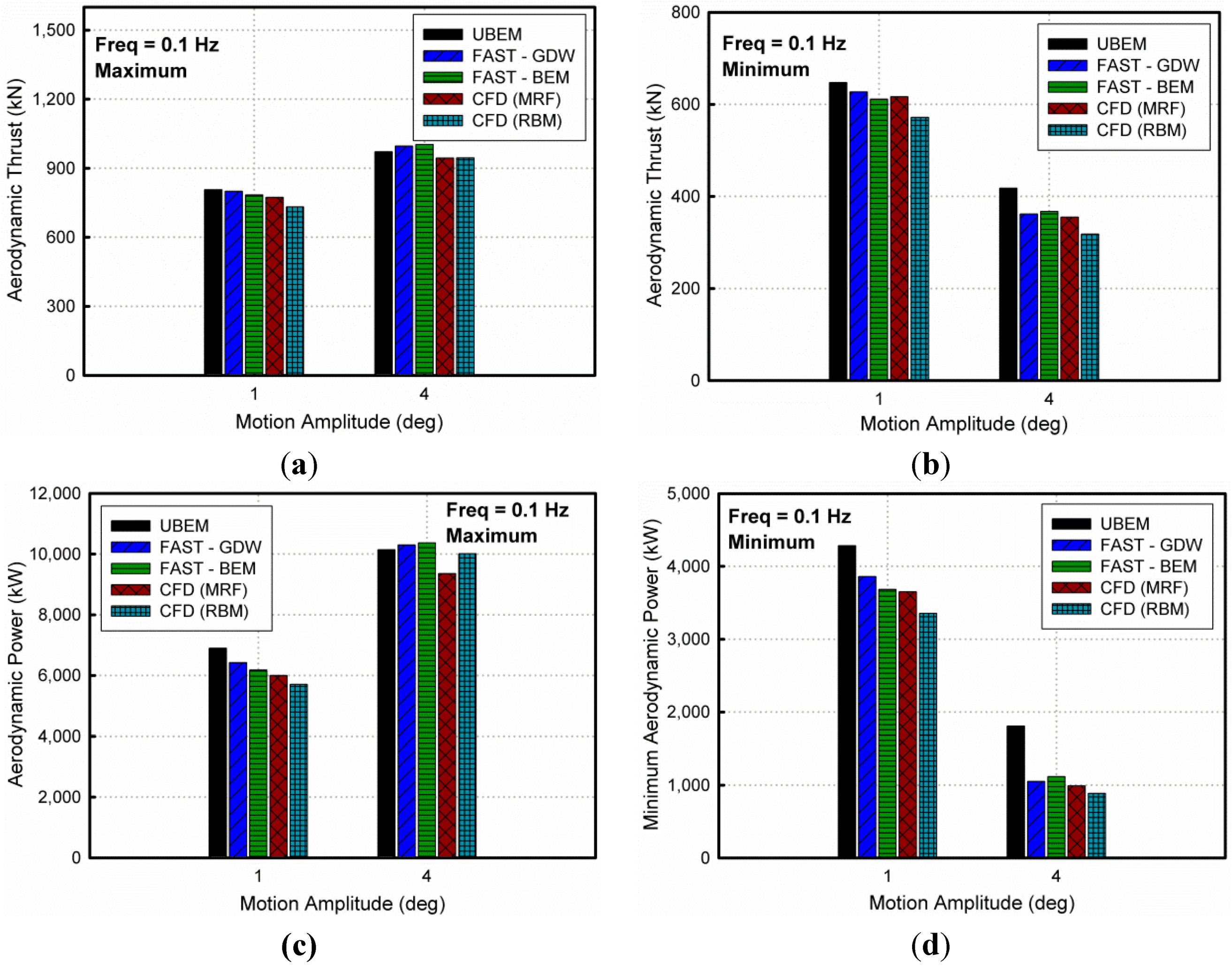
Figure 9.
Aerodynamic comparisons using the UBEM, CFD and FAST (NREL) methods for different pitching amplitudes of a FOWT (Freq = 0.1 Hz).
Figure 9.
Aerodynamic comparisons using the UBEM, CFD and FAST (NREL) methods for different pitching amplitudes of a FOWT (Freq = 0.1 Hz).
The GDW aerodynamic theory, which is based on a potential flow solution to Laplace’s equation, can be modeled with more flow states and a fully nonlinear implementation to account for the turbulence in and spatial variation of the inflow [
25]. However, the unsteady CFD can effectively predict the aerodynamic wake effect better than other numerical approaches. This method completely considers the viscous effect and vortex wake at the interference regime between the rotor blade and windmill. Particularly, an unsteady CFD-RBM approach that models real blade rotation about a hub center can accurately account for the flow field interaction between the blades and wake regime. Therefore, the unsteady CFD-RBM approach is expected to produce the lowest estimation of aerodynamic power and thrust responses because these values are over-predicted by the UBEM solver and other models.
As shown in
Figure 9, the aerodynamic power and thrust will increase with increasing amplitude of the pitching motion. At the maximum peak of aerodynamic power curves, the unsteady CFD-RBM predicted 5.7 MW and 10.0 MW of power for the different motion amplitudes of 1° and 4°, respectively. Compared to normal operating conditions for the wind turbine without wave effects, the aerodynamic power increased by approximately 14% and 100% for these respective amplitudes. This is a significant increase for a large wind turbine system. However, the aerodynamic thrusts obtained by unsteady CFD-RBM at maximum peak zone tend to slightly differ for 1° of amplitude pitching motion. The thrust increases to approximately 30% for a 4° amplitude pitching motion. In the UBEM simulation, a large variation in the aerodynamic load responses also appears for the different amplitudes. The aerodynamic power and thrust responses are therefore dominated by the frequency motion of the FOWT.
Figure 4 shows a typical pitching amplitude of the platform motion with reference to time or the azimuth angle of the rotor blade. The turbine rotor instantaneous position because of this pitching motion is illustrated in
Figure 10.
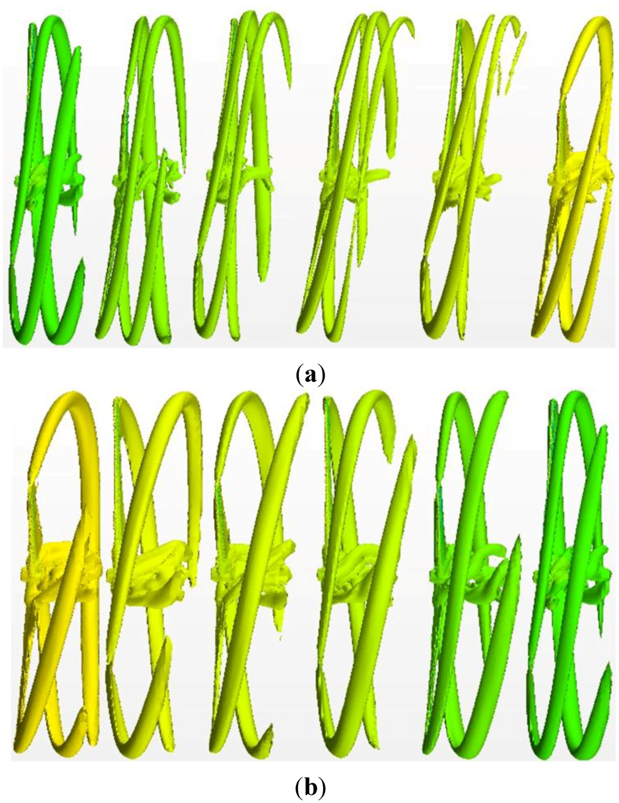
Figure 10.
Visualisation of instantaneous computed vortices for unsteady pitching of a FOWT simulation represented by an isosurface of vorticity (Amp = 4°, Freq = 0.1 Hz). (a) Downstream zone (Top: T1 → T6) and (b) Upstream zone (Bottom: T7 → T12).
Figure 10.
Visualisation of instantaneous computed vortices for unsteady pitching of a FOWT simulation represented by an isosurface of vorticity (Amp = 4°, Freq = 0.1 Hz). (a) Downstream zone (Top: T1 → T6) and (b) Upstream zone (Bottom: T7 → T12).
The computed iso-surfaces show the presence of instantaneous vortices beyond the wind turbine rotor during prescribed pitching motion. A side-view of the vortices is visualized. The blade tip vortices are strong and stable. Strong vortices also detach from the roots of the blades at which the geometry changes quickly from a DU40 airfoil profile to cylindrical posts attached to the hub. The vortical structures dissipate rapidly away from the regions covered by the grid refinements, (downstream of the rotor plane below 1 blade length as shown in
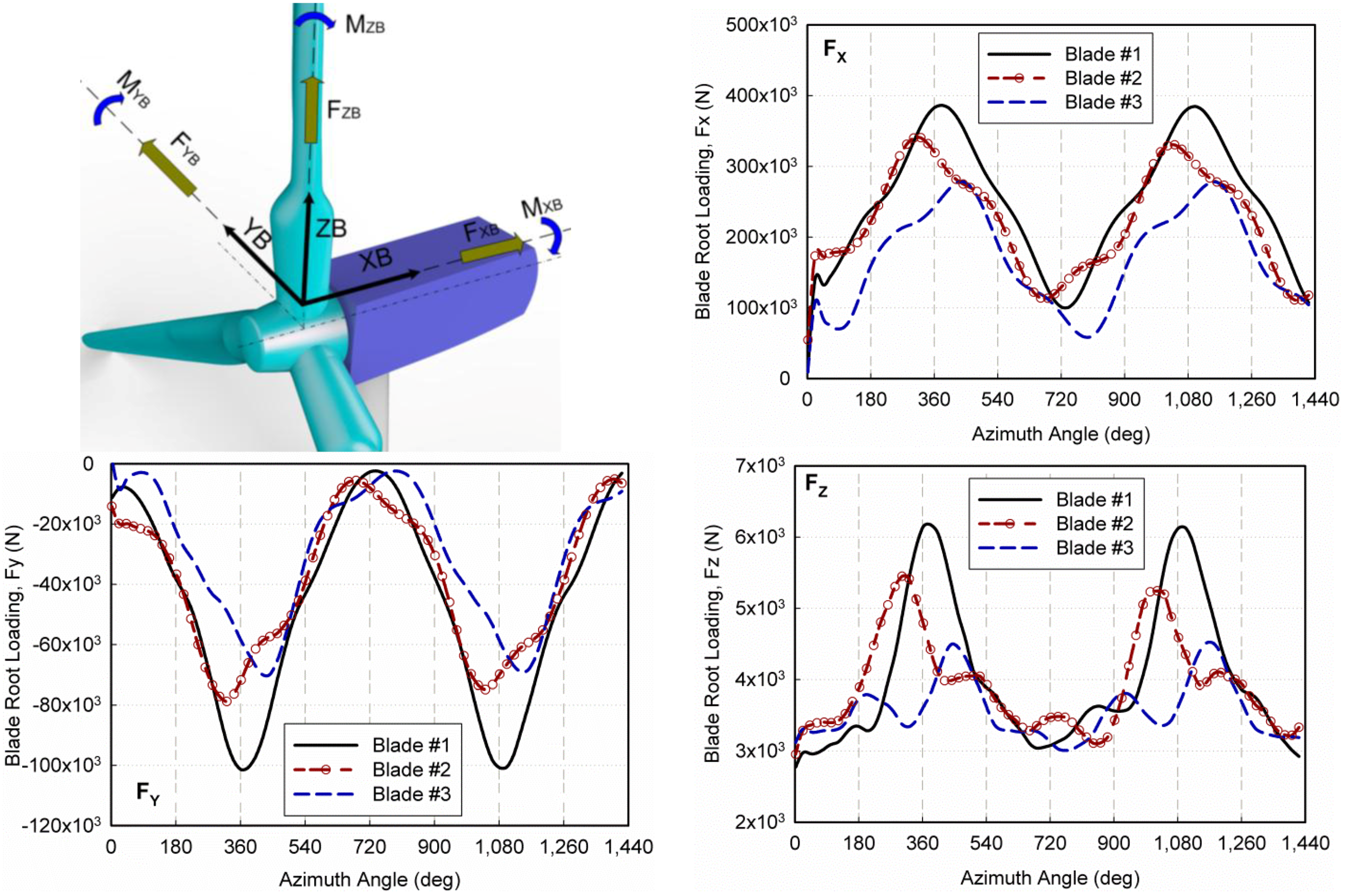
Figure 3). This complex physical flow can only be captured in the advanced CFD method. In the downstream region, the rotor blades deeply move in the wake zone, and they subsequently break off. The gaps among tip vortices showed that a strong interaction among the rotor blades and wake regimes appeared in the current study. The break-off of wake from the rotor blade and the increasing additional velocity contribution minimized vortices behind the rotor blade. The magnitude of wake also decreases as shown in the vortices view of the downstream zone. Similar behaviors in the wake pattern exist when rotor blades move in upstream regions. The gaps among tip vortices continue to increase because plane rotation still moves forward. Subsequently, the gaps decrease because rotor blades move downward. In this case, the wake magnitude increases as shown in the vortices view of the upstream zone. The unsteady CFD simulation tool is one of the best methods that can most accurately analyze the complex flow around the FOWT. The physical flow patterns can also be captured and visualized using the unsteady CFD method for physical investigation. It seems from the results that the conventional blade element momentum (BEM) theory needs to be additionally improved to account for the complex effect of induced velocity due to the free motion of the floating wind turbine. Typical integrated-aerodynamic loads on each wind turbine blade at the blade root are shown in
Figure 11. Blade #1 is located at 0 o’clock position on a clock since the wind turbine rotor initiates in pitching motion. To calculate the blade load based on the blade coordinate system, a special user field function has been originally developed based on the multiple reference frames algorithm. As shown in
Figure 11, all aerodynamic blade loads on each of the wind turbine blades varies as a sine function with a similar frequency of pitching motion. Because of blade position has the longest distance between the pitching rotating center and the local span position of the rotor blade, blade #1 is predicted to have the highest aerodynamic load due to highest additional velocity contributions, which is directly proportional to the angular velocity and distance.
Figure 11.
Unsteady aerodynamic load on the blade coordinate system by the CFD–RBM approach (Amp = 4°, Freq = 0.1 Hz).
Figure 11.
Unsteady aerodynamic load on the blade coordinate system by the CFD–RBM approach (Amp = 4°, Freq = 0.1 Hz).


