1. Introduction
In recent years, wind energy conversion systems (WECSs) have attracted more and more interest from researchers and engineers on a global scale. In the work of Jamil
et al. [
1], a traditional conversion system including a diode rectifier and a three-phase inverter is presented. In spite of the merits, such as simple construction and low cost, the bus voltage in such a system is relatively high due to the buck voltage characteristics of the voltage source inverter. This leads to an influence on the operational range of the wind power generation with variable speed and constant frequency. To solve this problem, a boost dc–dc converter is introduced between the diode rectifier and three-phase inverter [
2,
3,
4,
5,
6]. However, the two-stage structure will result in efficiency reduction and total costs increase of the conversion system.
As a novel and attractive technology for power electronic conversion [
7,
8,
9,
10], the Z-source inverter (ZSI) can either boost or buck its output voltage in a single stage without an extra power switch. In addition, the reliability of the inverter is substantially improved, because the shoot-through state, forbidden in voltage source inverter, is feasible in ZSI. Moreover, the output voltage distortion of the inverter is reduced, since there is no need to set dead time. As a result, the Z-source inverter is widely used in wind power and other renewable energy power generation systems in recent years [
11,
12,
13,
14].
However, the additional Z-source network greatly increases the size and weight of the system to which it is connected. Therefore, there are difficulties in equipment installation and transportation. At the same time, the system power density is also reduced. Recently, some research has shown that the size of Z-source capacitors can be reduced by ZSI topology improvement. Anderson
et al. [
15] proposed a quasi-Z-source inverter which reduces one capacitor voltage stress of Z-source network. Compared to the previous Z-source inverter, the quasi-Z-source inverter is smaller and cheaper under the same operating conditions. Moreover, an improved Z-source inverter topology is presented in [
16]. In comparison with the traditional Z-source inverter, the capacitor voltage stress of the Z-source network is reduced greatly with the same voltage boost ability, as the DC-side diode and inverter bridge are transposed. Thus, the low-voltage capacitors can be utilized to achieve a reduction in system volume and costs. Additionally, an enhanced Z-source inverter comprised by four inductors, two capacitors, and seven diodes is proposed in [
17]. With more passive components utilized, it can also reduce the Z-source capacitor voltage stress in higher power density. Although the mentioned structures are suitable for different specific applications [
18], it is significant that the capacitor voltage stress of the Z-source inverter can be reduced by improved pulse width modulation (PWM).
In the traditional PWM strategy for a Z-source inverter, the shoot-through time interval is divided into six equal parts [
19]. However, it needs to use relatively large capacitors to cope with the problem of different maximum and minimum amplitudes of the Z-source capacitor voltage, which thus results in increased ripple in capacitor voltage. In this paper, an improved PWM strategy is proposed. The shoot-through time is divided into six unequal parts to suppress capacitor voltage ripple in a Z-source network. The operating principle of the improved pulse width modulation strategy is analyzed in detail, and the comparison of Z-source capacitor voltage ripple under existing and improved pulse width modulation strategy is provided. Simulations and experiments are demonstrated to verify the performance of the proposed PWM strategy.
2. Working Principle
2.1. System Structure and Model Analysis
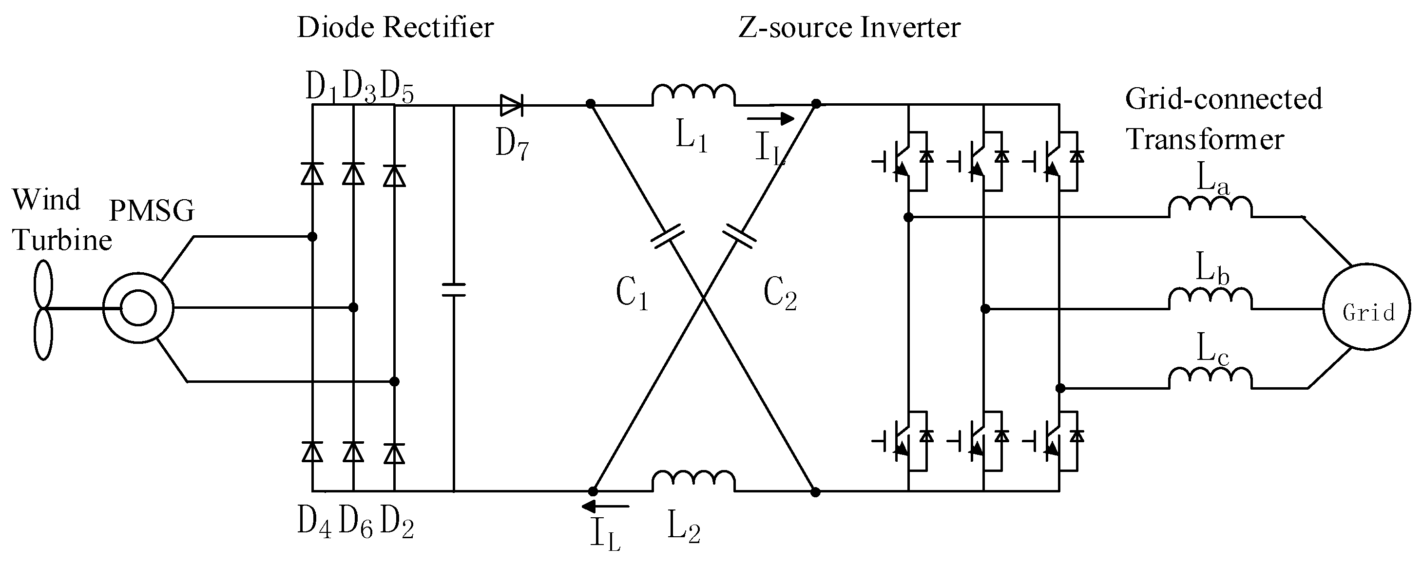
The configuration of the Z-source grid-connected wind generation system is shown in
Figure 1. This system consists of the wind turbine, the permanent-magnet synchronous generator (PMSG), the diode rectifier, the Z-source inverter, and the grid-connected transformer.
Figure 1.
The topology of Z-source grid-connected wind generation system. PMSG: permanent-magnet synchronous generator.
Figure 1.
The topology of Z-source grid-connected wind generation system. PMSG: permanent-magnet synchronous generator.
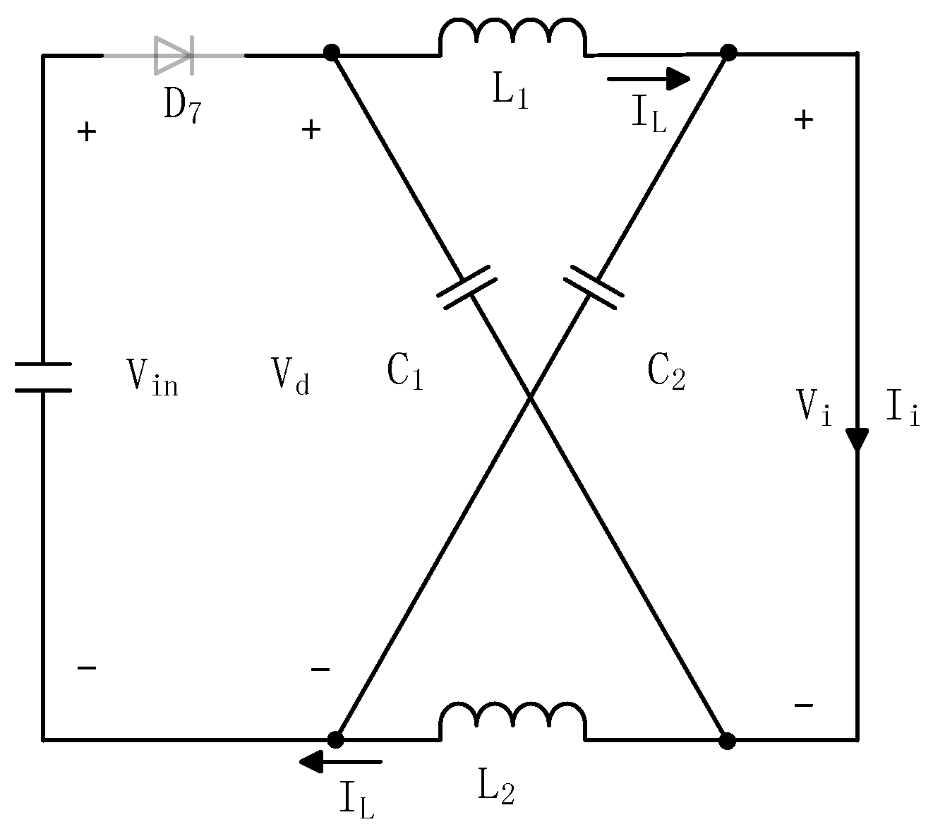
As shown in
Figure 2, the inverter bridge is equivalent to a current source when it works in the non-shoot-through zero state. Consider the symmetry of the Z-source network [
20], we have:
where
VC1,
VC2 are the voltage of Z-source capacitors, and
VL1,
VL2 are the voltages of Z-source inductors.
From the equivalent circuits shown in
Figure 2, the equations can be obtained as follows:
where
ID is the current through
D7,
IL is the current through the Z-source inductor,
Ii is the equivalent current through the inverter bridge,
Vin is the output voltage of the diode rectifier,
Vi is the input voltage of the inverter bridge, and
LZ is the inductance of the Z-source inductor.
Figure 2.
Equivalent circuit of the Z-source inverter (ZSI) in the non-shoot-through zero state.
Figure 2.
Equivalent circuit of the Z-source inverter (ZSI) in the non-shoot-through zero state.
As illustrated in
Figure 3, the inverter bridge is equivalent to a short circuit when it operates in the shoot-through zero state. In this case, the diode
D7 is in the OFF state. From
Figure 3, the following equations are obtained:
Figure 3.
Equivalent circuit of the Z-source inverter in the shoot-through zero state.
Figure 3.
Equivalent circuit of the Z-source inverter in the shoot-through zero state.
In steady state, it is noticed that the average voltage of the Z-source inductors in one switching period is zero. According to Equations (2) and (3), it can be calculated as:
where
T0 is the time of shoot-through zero state in a switching period, and
D0 is the shoot-through duty cycle.
Based on Equations (3) and (4), it can be obtained by:
where
VD is the voltage of diode
D7.
In Equation (5), we can clearly see that diode D7 will be shut off when the Z-source inverter is in the shoot-through zero state. In this case, the Z-source network can no longer get power from the PMSG.
In the non-shoot-through zero state, from Equations (2) and (4), we have:
In the shoot-through zero state, from Equations (3) and (4), it can be obtained that:
2.2. Traditional PWM Strategy for ZSI
In traditional ZSI PWM strategy, the shoot-through time is divided into six equal parts. They are distributed to the adjacent active state vectors and both sides of the zero vectors. The traditional PWM scheme for ZSI is shown in
Figure 4, where
TS represents a switching period,
TZ is the zero state time in a switching period,
T0 is the shoot-through time in a switching period,
T1 and
T2 are the active state time in a switching period,
Tsh is one-sixth of
T0, and
t1–
t6 are the moments of switching operations in a half of a switching period.
Figure 4.
Diagram of traditional pulse-width modulation (PWM) scheme for ZSI.
Figure 4.
Diagram of traditional pulse-width modulation (PWM) scheme for ZSI.
The diagram of Z-source capacitor voltage ripple with the traditional PWM scheme is shown in
Figure 5. It can be seen that the Z-source inductor is charged by the Z-source capacitor when the Z-source inverter works in the shoot-through zero state, which can decrease the voltage of the Z-source capacitor. However, the voltage will increase as the capacitor is charged by the inductor when the Z-source inverter operates in the non-shoot-through zero state. Since the shoot-through time is equally distributed to the adjacent state vectors, the capacitor voltage has identical decreasing time, while the increasing time is determined by the non-shoot-through zero state. Therefore, the Z-source capacitor voltage ripple is not optimized.
Figure 5.
Diagram of Z-source capacitor voltage ripple with traditional PWM scheme.
Figure 5.
Diagram of Z-source capacitor voltage ripple with traditional PWM scheme.
From
Figure 5, the moments of switching operations can be calculated by:
The Z-source capacitor voltage from t
1 to t
6 can be expressed as follows:
And the Z-source capacitor voltage ripple is the maximum value of six peaks within half a switching period, which can be described as:
2.3. Improved PWM Strategy for ZSI
In this paper, an improved PWM strategy is proposed to minimize Z-source capacitor voltage ripple. In contrast to the traditional scheme, the shoot-through time of the proposed method is divided into six unequal parts. And they are distributed to the adjacent active state vectors and both sides of the zero vectors. The total shoot-through time in a switching period is kept constant, because of its influence on the boost voltage ability. Meanwhile, the active states are maintained the same, because the shoot-through zero states only take parts of zero states. It is obvious that the arrangement of the shoot-through time affects the voltage of the Z-source capacitor. Therefore, the Z-source capacitor voltage ripple can be optimized.
In
Figure 6, the improved PWM scheme for ZSI is shown, where
Ta,
Tb, and
Tc are the reassigned shoot-through time according to the increasing and decreasing time of the Z-source capacitor voltage. The sum of
Ta,
Tb and
Tc is half of the total shoot-through time in a switching period. The diagram of Z-source capacitor voltage ripple with improved PWM scheme is illustrated in
Figure 7, where
a,
b, and
c are the increased values of the Z-source capacitor voltage. From
Figure 7, the following equations can be obtained:
On the basis of Equations (10) and (11), the Z-source capacitor voltage ripple can be expressed as:
In order to minimize the ripple of the Z-source capacitor voltage, the following equations should be established:
And the decreased values of the Z-source capacitor voltage in shoot-through time
Ta,
Tb, and
Tc are:
Therefore, the shoot-through time
Ta,
Tb, and
Tc can be obtained as:
As
a,
b, and
c are proportional to the corresponding state time, it can be expressed as:
From Equation (16), it can be calculated as:
The maximum and minimum values of Z-source capacitor voltage are kept equal in each active state. In the same working conditions, the Z-source capacitor voltage ripple is reduced. Therefore, smaller capacitors can be utilized under the same ripple requirements.
Figure 6.
Diagram of improved PWM scheme for ZSI.
Figure 6.
Diagram of improved PWM scheme for ZSI.
Figure 7.
Diagram of Z-source capacitor voltage ripple with improved PWM scheme.
Figure 7.
Diagram of Z-source capacitor voltage ripple with improved PWM scheme.
2.4. Control Strategy of the Z-Source Grid-Connected Wind Generation System
Generally, the double closed-loop controller, including the voltage outer-loop and current inner-loop, is always adopted in the existing three-phase voltage-source inverter for grid connection [
21]. Based on this, the control system of the proposed Z-source grid-connected wind generation also combines the double closed-loop controller, which includes the speed outer-loop and current inner-loop. From Equations (3) and (4), the average dc voltage on the inverter bridge can be expressed as:
It can be seen that the average dc voltage on the inverter bridge will remain stable as long as the Z-source capacitor voltage stays constant when the shoot-through duty cycle is fixed. Therefore, the Z-source capacitor voltage is controlled directly in voltage outer-loop. And the speed of the PMSG can be controlled flexibly by controlling the shoot-through duty cycle when the Z-source capacitor voltage remains stable.
In this paper, the current control based on the synchronously rotating coordinates is utilized in the current inner-loop. The d-axis of the d–q coordinates is made being coincided with the grid voltage vector
. Thus, the following can be obtained:
The double value logical switch function
SK (
K = a, b, c) is defined as:
when SK = 1, the top switch of the phase leg is being turned on and the bottom switch of the phase leg is being turned off;
when SK = 0, the top switch of the phase leg is being turned off and the bottom switch of the phase leg is turned on.
Through the synchronous rotating transformation, it can be expressed as:
where
ed and
eq are the d-axis and q-axis component of the electromotive force vector of the grid, respectively;
id and
iq are the d-axis and q-axis component of the grid current vector, respectively; and
Sd and
Sq are the quantities transformed by
Sa,
Sb, and
Sc in the synchronously rotating coordinates.
The state feedback decoupled control is applied to achieve good performance. The output voltage of the Z-source inverter can be expressed by:
where
KP and
KI are the P-gain and I-gain of the PI controllers, respectively;
vd and
vq are the d-axis and q-axis component of the output voltage vector of the Z-source inverter, respectively; and
id* and
iq* are the d-axis and q-axis component of instruction current vector of the grid, respectively.
The mechanical power delivered by a wind turbine is expressed as [
6]:
where
CP is the power coefficient defined as the ratio of turbine power to wind power and depends on the aerodynamic characteristics of blades. ρ is the air density,
r is the radius of the turbine blades,
vw is the wind velocity.
The tip speed ratio λ is defined as:
where ω
s is the angular speed of the rotor.
The wind speed and wind turbine angular speed is proportional when the state of the wind machine is running at the optimum tip speed ratio:
where λ
opt is the optimum tip speed ratio.
The maximum power output by the wind turbine is given by:
and then the maximum torque is:
where
Kopt is a constant determined by the wind turbine characteristics.
Figure 8a is mechanical power
versus rotor angular speed curves calculated by Equation (25).
Figure 8b is mechanical torque
versus rotor angular speed curves calculated by Equation (26).
Figure 8.
Wind turbine characteristics (a) Mechanical power versus rotor angular speed; (b) Mechanical torque versus rotor angular speed.
Figure 8.
Wind turbine characteristics (a) Mechanical power versus rotor angular speed; (b) Mechanical torque versus rotor angular speed.
The instruction shoot-through duty cycle is determined by controlling the Z-source inductor current, and the inductor instruction current is determined by speed controlling of the PMSG. The structure of the control system for Z-source grid-connected wind generation is shown in
Figure 9.
Figure 9.
The control system of three-phase Z-source grid-connected inverter.
Figure 9.
The control system of three-phase Z-source grid-connected inverter.
3. Simulation and Experimental Results
In order to verify the theoretical analysis, simulation model and experimental system are established based on the following parameters:
- (1)
Rated speed of PMSG: 1500 RPM;
- (2)
Rated capacity: 7.5 kW;
- (3)
Grid line-line voltage: 380 V/50 Hz;
- (4)
Z-source capacitor voltage: 573 V;
- (5)
Capacitance of Z-source capacitor: 1000 μF;
- (6)
Inductance of Z-source inductor: 1.5 mH.
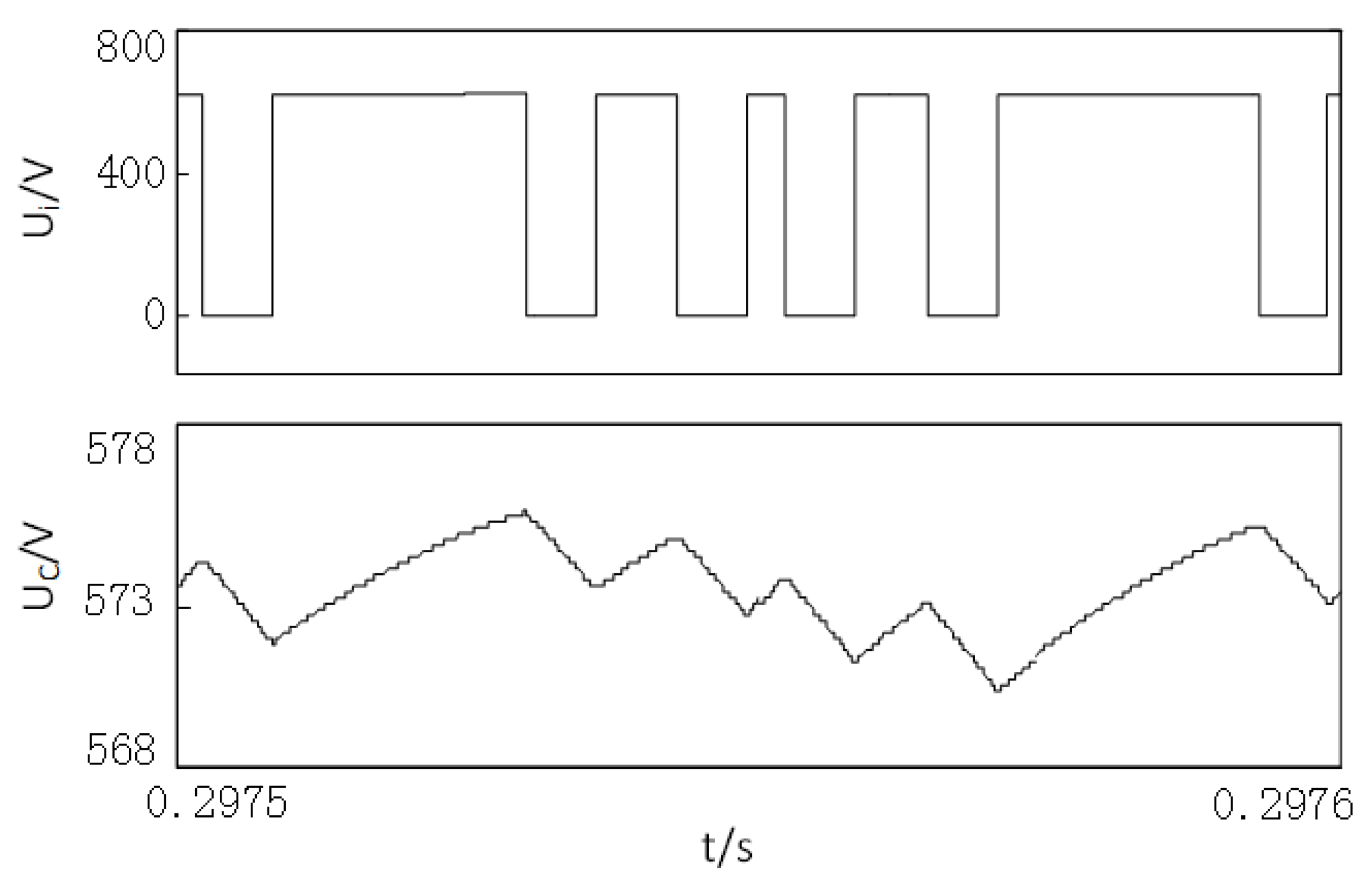
The simulation waveforms with traditional PWM scheme in 0.2 s are shown in
Figure 10, where the output three-phase current, the Z-source inductor current, the input voltage of the inverter bridge, and the Z-source capacitor voltage are included. It can be seen that the grid-connected current is a sinusoidal wave; the input voltage of inverter bridges is controlled at 637 V; the Z-source inductor current is relatively stable; the maximum voltage ripple through the Z-source capacitor is about 6 V. The simulation waveforms with traditional PWM scheme in a switching period is shown in
Figure 11. It can be seen that there are 6 equal shoot-through states in a switching period. Therefore, Z-source capacitor voltage has equivalent decreasing time, while the increasing time of Z-source capacitor voltage is determined by the non-shoot-through zero state. The Z-source capacitor voltage ripple is relatively large.
The simulation waveforms with improved PWM scheme in 0.2 s are shown in
Figure 12. It can be seen that the grid-connected current is a sinusoidal wave; the input voltage of inverter bridges is also controlled at 637 V; the Z-source inductor current is relatively stable; the maximum voltage ripple through the Z-source capacitor is about 3.8 V, which has obviously been decreased compared to the traditional PWM strategy shown in
Figure 10. The simulation waveforms with improved PWM scheme in a switching period is shown in
Figure 13. It can be seen that there are six unequal shoot-through states in a switching period. Therefore, Z-source capacitor voltage has symmetrical maximum amplitude and minimum amplitude in one state. Z-source capacitor voltage ripple is improved.
Figure 10.
Simulation waveforms in the traditional PWM scheme.
Figure 10.
Simulation waveforms in the traditional PWM scheme.
Figure 11.
Amplified waveforms of the input voltage of the inverter bridge and the Z-source capacitor voltage corresponding to
Figure 10.
Figure 11.
Amplified waveforms of the input voltage of the inverter bridge and the Z-source capacitor voltage corresponding to
Figure 10.
Figure 12.
Simulation waveforms in the improved PWM scheme.
Figure 12.
Simulation waveforms in the improved PWM scheme.
Figure 13.
Amplified waveforms of the input voltage of the inverter bridge and the Z-source capacitor voltage corresponding to
Figure 12.
Figure 13.
Amplified waveforms of the input voltage of the inverter bridge and the Z-source capacitor voltage corresponding to
Figure 12.
An experimental platform has been built to compare the improved PWM strategy and traditional PWM strategy. TMS320F28335DSP is used to realize the control strategy. An induction motor is utilized to drag the PMSG to imitate a wind turbine. The energy generated by PMSG pass diode rectifier and Z-source inverter then flow into the grid.
Figure 14 shows the experimental prototype. The switching frequency is 10 kHz. The experimental results are collected by the Tektronix oscilloscope.
Figure 14.
A picture of the experimental system.
Figure 14.
A picture of the experimental system.
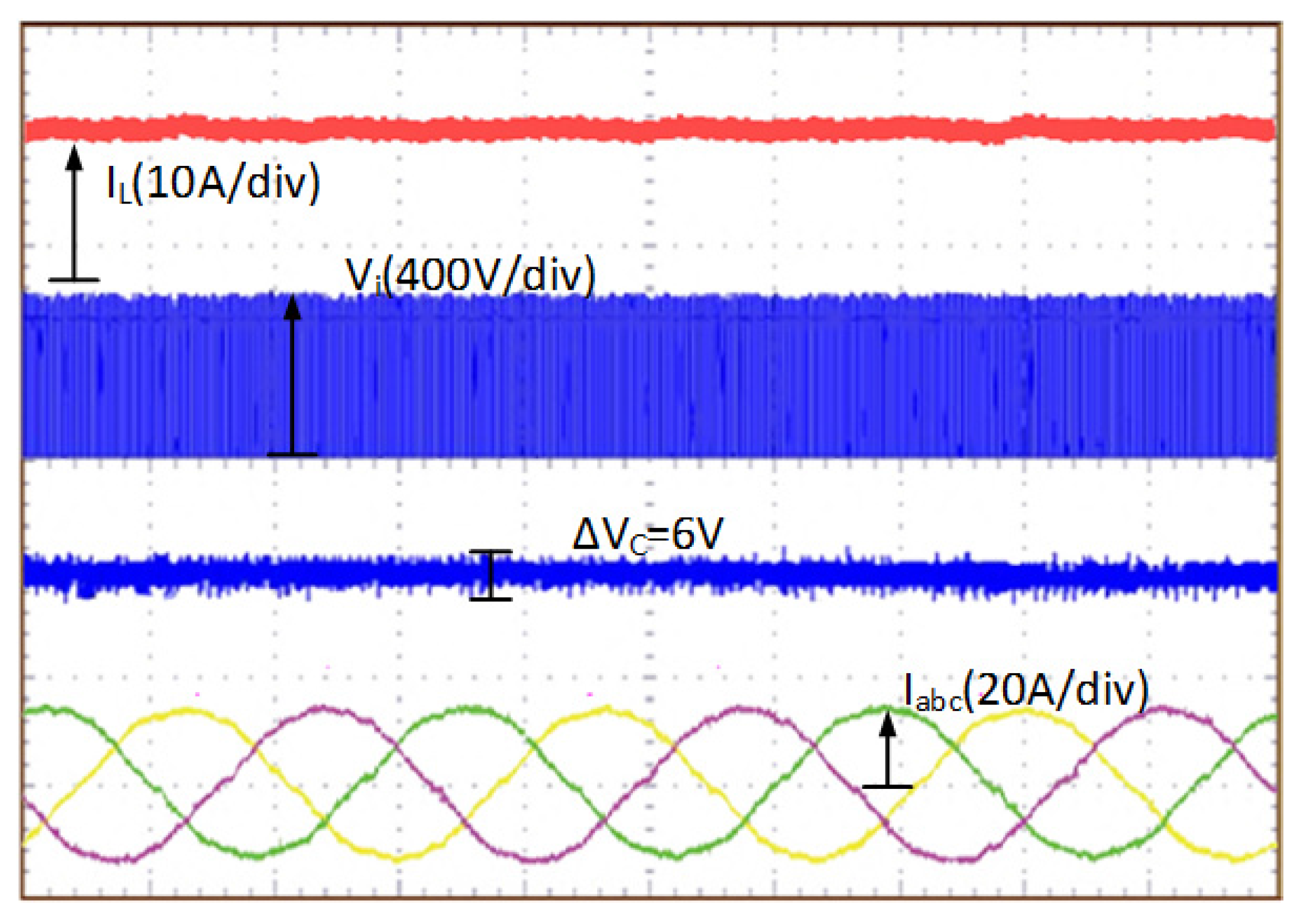
The experimental waveforms with traditional PWM scheme in 0.6 s are shown in
Figure 15, where the Z-source inductor current, the input voltage of inverter bridge, the Z-source capacitor voltage, and the output three-phase current can be seen. The ripple voltage of the Z-source capacitor is about 6 V, which is consistent with the simulation results. The experimental waveforms with the traditional PWM scheme in two switching periods is shown in
Figure 16. It can be seen that twelve equal shoot-through states exist in two switching periods.
Figure 15.
Experimental waveforms in the traditional PWM scheme.
Figure 15.
Experimental waveforms in the traditional PWM scheme.
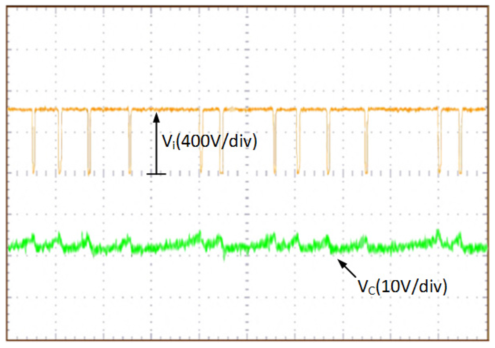
Figure 16.
Amplified waveforms of the input voltage of the inverter bridge and the Z-source capacitor voltage corresponding to
Figure 15.
Figure 16.
Amplified waveforms of the input voltage of the inverter bridge and the Z-source capacitor voltage corresponding to
Figure 15.
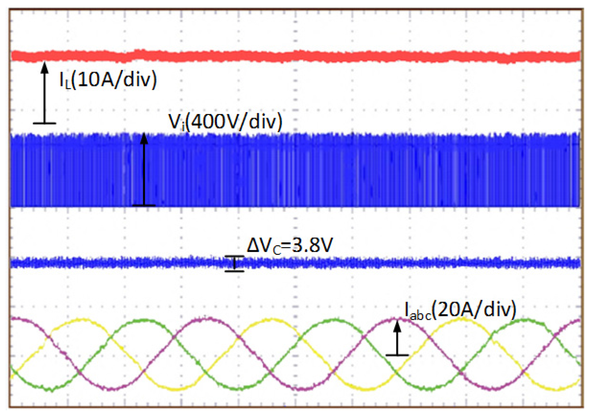
The experimental waveforms with the improved PWM scheme in 0.6 s is shown in
Figure 17. It can be seen that the ripple voltage of Z-source capacitor is about 3.8 V, which has obviously been decreased compared to the traditional PWM strategy shown in
Figure 15.
Figure 18 shows that twelve unequal shoot-through states exist in two switching periods, which agrees with the simulation results.
With the improved PWM scheme, the ripple voltage of the Z-source capacitor is significantly reduced by 37% compared with the traditional strategy. Thus, the cost of the Z-source capacitor can be reduced under the same ripple requirements.
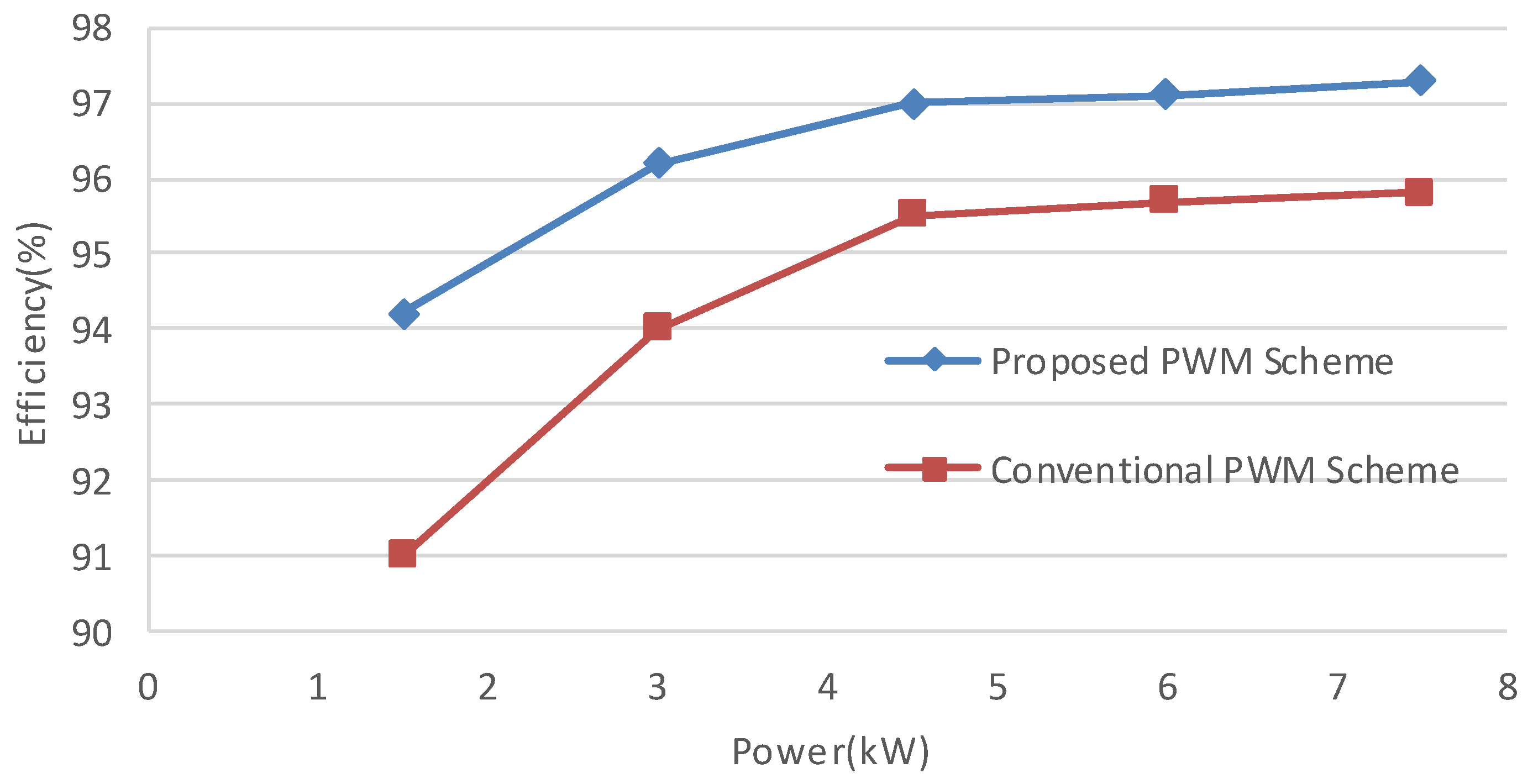
The experimental result-based efficiency comparison of the proposed method and the conventional one is shown in
Figure 19. It can be seen from
Figure 19 that the converter’s efficiency of the proposed PWM scheme is higher than that of the conventional one in different typical power conversion levels.
Figure 17.
Experimental waveforms in the improved PWM scheme.
Figure 17.
Experimental waveforms in the improved PWM scheme.
Figure 18.
Amplified waveforms of the input voltage of the inverter bridge and the Z-source capacitor voltage corresponding to
Figure 17.
Figure 18.
Amplified waveforms of the input voltage of the inverter bridge and the Z-source capacitor voltage corresponding to
Figure 17.
Figure 19.
ZSI efficiency curves when using the proposed PWM scheme and the conventional PWM scheme.
Figure 19.
ZSI efficiency curves when using the proposed PWM scheme and the conventional PWM scheme.


