Article

Analysis and Design of an Active Stabilizer for a Boost Power Converter System

1
School of Automation, Northwestern Polytechnical University, Xi’an 710072, China
2
Research Group in Electrical and Electronics, Université de Lorraine, 54518 Vandoeuvre-les-Nancy, France
3
Department of Electrical and Computer Engineering, Concordia University, Montreal, QC H3G 1M8, Canada
4
Research Institute of Transport, Energy and Society (IRTES), University of Technology of Belfort-Montbeliard, 90010 Belfort CEDEX, France
*
Author to whom correspondence should be addressed.
Energies 2016, 9(11), 934; https://doi.org/10.3390/en9110934
Submission received: 2 August 2016 / Revised: 2 November 2016 / Accepted: 4 November 2016 / Published: 10 November 2016

Abstract

:
In electrical power converter systems, the presence of an LC input filter can efficiently reduce the Electromagnetic Interference (EMI) effect, and at the same time protect the converter and the load from being impacted by sharp input impulse voltages. However, for transportation applications, the weight and size limitations of input LC filters for power converters have to be taken into consideration. The reduction of LC filter size may impair the system stability margin and dynamic response. In serve cases, the system may even become unstable. Thus, in order to ensure the system stability while minimizing the input LC filter size, the implementation of a stabilizer for the system control is needed. In this paper, a novel digital stabilizer design method is proposed for a boost power converter with a small input LC filter. The proposed method is based on input filter inductance current measurements and DSP (Digital Signal Processor) -based digital stabilizer design. Simulation and experimentation confirm the validity of the proposed approach.

1. Introduction

Power electronic devices have been widely used in modern electrical power generation and conversion systems. In particular, power converters play an important role in electrified powertrains in transportation applications, such as electric/hybrid vehicles (EV/HEV) and more-electric-aircraft (MEA) [1,2].
In those on-board DC (direct current) microgrid systems, an input LC filter is usually added at the DC/DC power converter stage to solve the problem of EMI and instantaneous impulse voltage [3,4,5,6], but it is known that with the presence of an LC filter in cascade, the system damping ratio may be decreased and instability risks may be increased by the interaction between the filter and the converter [1,7].
In some typical applications such as more-electric-aircraft, submarines, ships and hybrid electric vehicles, the stability of the system is important for the user safety and must be carefully considered. Furthermore, volume and weight constraints should also be considered [8,9].
In order to meet the cascaded system (LC filter and DC/DC converter) stability requirements, one solution is to damp the input filter using an impedance criterion (Middlebrook criterion) [10,11,12]. Although this method could make the system stable, it increases the power loss and adds more volume to the system.
Another solution to reduce the risk of system instability is to use a larger capacitor in the input filter. However, in transportation applications, the volume and weight of the overall system have to be carefully taken into consideration. Using a smaller capacitor can not only reduce the power system volume, but also reduce the system cost [13,14].
To solve the abovementioned stability and sizing problems in cascaded LC filter and DC/DC power converters, several methods have already been discussed in the literature. To solve the instability problem, small-signal methods [15] or large-signal methods are used [8]. Nonlinear control methods are also used to solve this problem based on synergetic control [16], sliding mode control [17,18], phase-plane analysis [19] and T-S multi-modeling [20]. A compensation method using output voltage has been presented in [7,9], use of a virtual resistance and virtual inductance were presented in [21,22], use of a virtual capacitor was introduced in [8,23], and a global stabilization method using Lyapunov equation is proposed in [24].
This paper presents a novel stabilizer technique to suppress the oscillation and stabilize the system. Compared to the methods mentioned in [1,3,7,9,18], the proposed method offers two innovative improvements. Firstly, instead of generating the stabilizing signal by the output voltage or the capacitor voltage, the proposed method uses the input filter inductance current. Compared to voltage measurement, the current measurement could isolate the system and break the limitation of the sensor bandwidth, thus improve the system reliability. Secondly, instead of adding the stabilizing signal to the original loop, the method proposed in this paper directly adds the signal of the stabilizer to the main duty cycle. It does not change the original control structure. In this way, the implementation of control diagram can be simplified.
This paper is organized in five sections: the system being studied and the mathematical model is presented and discussed in the second section. In Section 3, the stability analysis of the novel digital stabilizer is given in details. In Section 4 and Section 5, the validity of the proposed approach is further confirmed by both simulation and experimental results. The last section gives the conclusions.

2. System Model and Control

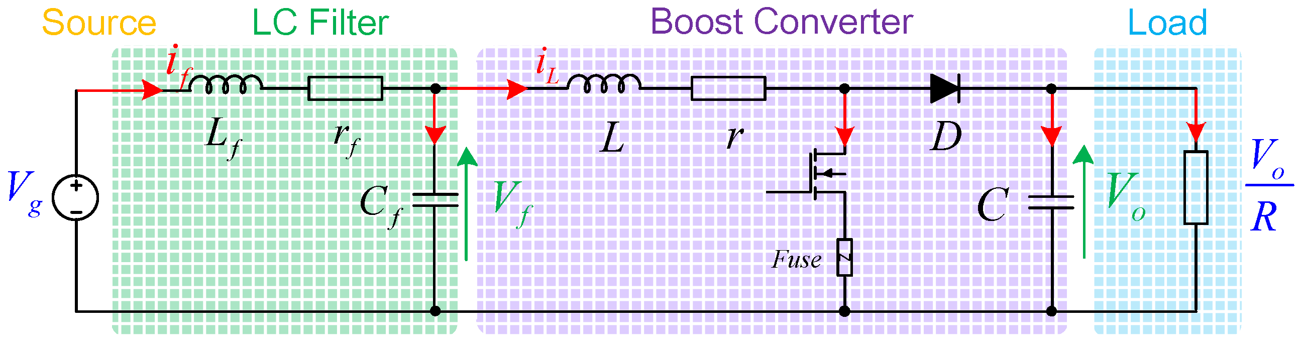
2.1. DC Power System Model

In transportation applications, DC power sources such as batteries or fuel cells are generally used. Thus, the power source can be replaced by an equivalent low voltage DC source. The input LC filter is placed between the DC source and the DC/DC converter. In this paper the resistive load is supplied by the tightly controlled Boost converter using pulse width modulation (PWM) technique. The topological structure of the studied system is presented in Figure 1.
For the studied DC power system, the input DC source voltage is Vg and the output voltage is Vo. The LC filter consists an inductance Lf, an equivalent resistance rf and a capacitor Cf. The inductance L, the capacitor C and the equivalent resistance r are the parameters of the boost converter.

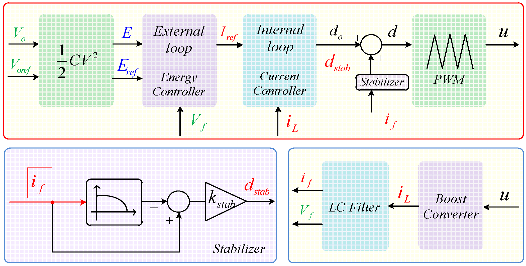
2.2. Control and Design of Stabilizer

To control the system, a double control loop is used in this model. Instead of controlling the voltage, the energy stocked in the capacitance is controlled [7,9,25]. The external loop (energy loop) first generates the error signal by comparing E (0.5 CVo2) and Eref (0.5 CVref2). Then the energy control provides a reference current of internal loop, as shown in:
I r e f = P r e f V f
P r e f = K p e x ( E r e f E ) + K i e x ( E r e f E ) d t
where, Kpex, Kiex, Kpin and Kiin are the PI parameters of the controllers. The internal loop (current loop) generates the main duty cycle d0 for the boost converter. The control strategy is shown in Figure 2:
d 0 = K p i n ( I r e f i L ) + K i i n ( I r e f i L ) d t
Thus, in order to ensure the system stability, a stabilizer should be added. In this paper, the proposed stabilizer design approach is based on the measurement of the inductance current of the input filter. In the proposed design, the measured inductance current is firstly filtered by a high-pass filter (HPF) to eliminate fundamental components (thus keeping only the DC current variation). The filtered value is then multiplied by a proportional compensator coefficient Kstab. The stability compensation result, noted as dstab, is then added directly to the boost converter main duty cycle d0 calculated separately from the stabilizer. The stability compensator dstab is calculated by Equation (4), and the modified duty cycle d is given by Equation (5):
d s t a b = K s t a b H P F ( i f )
d = d 0 + d s t a b
By using the HPF in the structure, the stabilizer only reacts on the dc current variations, therefore, the amplitude of dstab is null in steady state. Thus, the operating point and control structure of the system are not modified. This stabilizer has a very simple structure but it is effective at improving the system stability margins and thus the reliability of the system, as shown and discussed in the following section.

2.3. Mathematical Modeling

To achieve an optimum tuning of the stabilizer, a mathematical model is needed to analyze its influence on the system dynamic and stability. In this section, an analytical system model with the stabilizer for the studied system shown in Figure 1 and Figure 2 are developed. The input filter inductance current (if), the input filter capacitor voltage (Vf), the Boost converter inductance current (iL) and the output voltage (Vo) are the state variables of the system. Furthermore, there are three other state variables: Si and Sv represent the integral actions in the current control loop and the energy control loop; f1 is the state variable of the high-pass filter. Thus, the system can be modeled by Equation (6):
{ d i f d t = V g r f i f V f L f d V f d t = i f i L C f d i L d t = V f i L r ( 1 d ) V o L d V 0 d t = ( 1 d ) i L V o / R C d S i d t = I r e f i L d S v d t = 1 2 C ( V o r e f 2 V o 2 ) d f 1 d t = w n f 1 + w n i f
In order to simplify the system stability analysis, the studied model needs to linearize at its equilibrium point. To obtain the equilibrium point X0 (and thus the steady-state) of the system, one can simply set all the time derivatives (left-hand side of each equation) of Equation (6) to zero. The solution of the corresponding algebraic equation system is the voltages and currents in the steady-state given by X0:
X 0 = [ I f 0 V f 0 I L 0 V o 0 S i 0 S v 0 F 10 ] T
According to the small-signal theory, each variable X is expressed as the sum of its steady state value X0 and a small variation x:
X = X 0 + x
Thus, two new state vectors can be defined as:
X = [ i f V f i L V o S i S v f 1 ] T
x = [ i ^ f v ^ f i ^ L v ^ o s ^ i s ^ v f ^ 1 ] T
By substituting Equations (7)–(10) into Equation (6), Equation (11) is obtained. It represents a nonlinear state-space model in the form dx/dt = f(x). Indeed, each differential equation in Equation (11) depends only on the state vector x and a set of constants considered as the parameters of the system:
d d t [ i ^ f v ^ f i ^ L v ^ o s ^ i s ^ v f ^ 1 ] = [ V g r f ( I f 0 + i ^ f ) ( V f 0 + v ^ f ) L f ( I f 0 + i ^ f ) ( I L 0 + i ^ L ) C f ( V f 0 + v ^ f ) ( I L 0 + i ^ L ) r ( 1 d ) ( V o 0 + v ^ o ) L ( 1 d ) ( I L 0 + i ^ L ) ( V o 0 + v ^ o ) / R C I r e f ( I L 0 + i ^ L ) 1 2 C ( V o r e f 2 ( V o 0 + v ^ o ) 2 ) w n ( F 10 + f ^ 1 ) + w n ( I f 0 + i ^ f ) ]
The parameters Iref, d and dstab are defined in the following equations:
I r e f = P r e f V f = 1 V f 0 + v ^ f ( 1 2 C K p e x ( V o r e f 2 ( V o 0 + v ^ o ) 2 ) + K i e x ( S v 0 + s ^ v ) )
d = K p i n ( I r e f ( I L 0 + i ^ L ) ) + K i i n ( S i 0 + s ^ i ) + d s t a b
d s t a b = K s t a b ( I f 0 + i ^ f F 10 f ^ 1 )
The system presented by Equation (11) is nonlinear. For system stability analysis, the model of the system must be linearized first around its operating point. The Jacobian linearization method is used in this paper, and the linearized model can be defined as:
d x d t = A ( X 0 ) x + B U
This linearized model will be used for the analysis of the dynamic stability in the subsequent chapters.

3. Stability Analysis

The stability behavior of the studied system is investigated based on a Bode diagram and Lyapunov first method in this section. Above all, the stability analysis will be made from the viewpoint of loop gain and resonance peak, by the Bode diagram, to ensure a good performance of the control scheme and see the resonance suppression capability of the stabilizer. Secondly, the stability analysis will be made, from the viewpoint of the whole system by the Lyapunov first method, to see the stability margin in different cases and explore the optimal value of the compensator coefficient Kstab. The parameters used here are presented in Table 1.

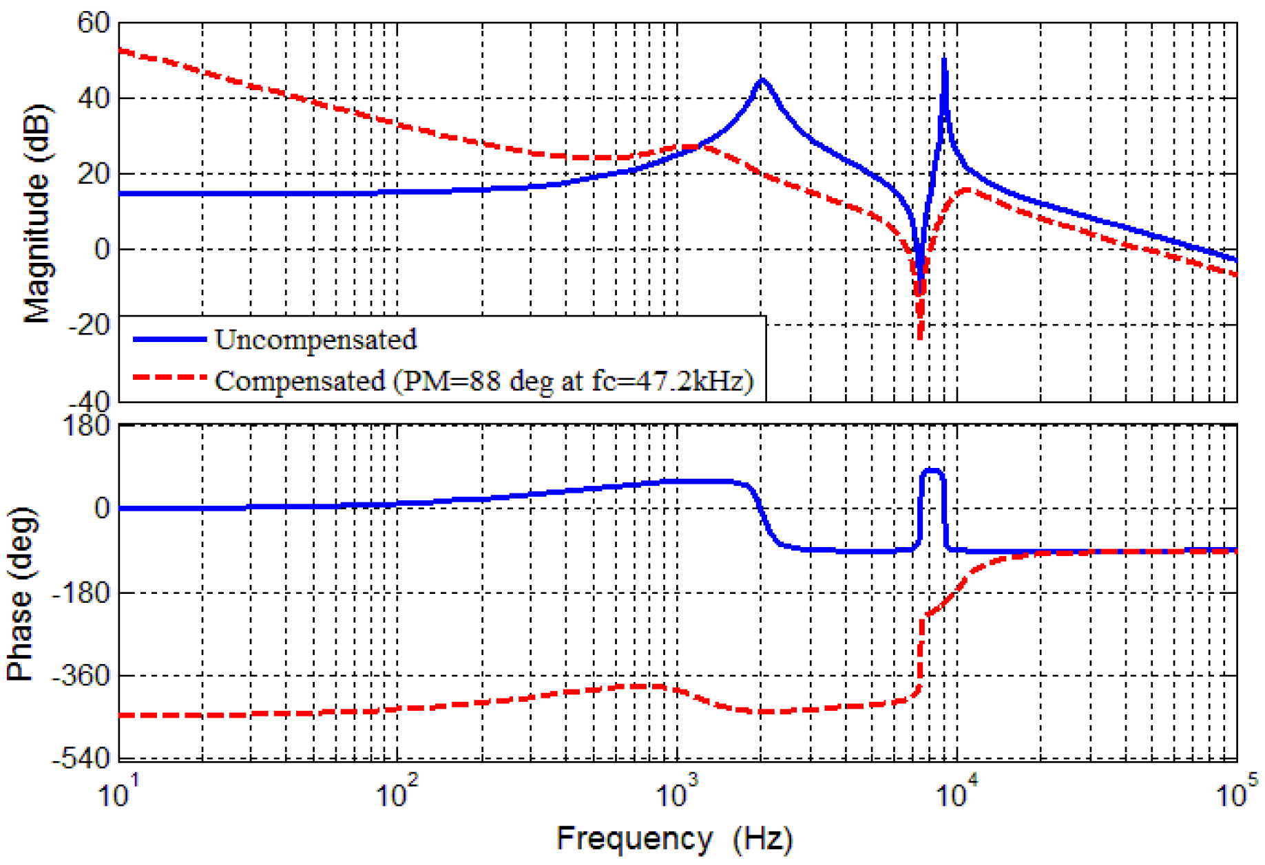
3.1. Analysis of the Loop Gain and Resonance Peak by Bode Diagram

It is generally known that the presence of an LC input filter changes all the transfer functions of the system and has a degradation effect on the dynamic performance. The transfer functions relating the duty-cycle to output voltage G v o d ( s ) and the duty-cycle to the Boost inductance current G i L d ( s ) are obtained. The bode diagram of G i L d ( s ) is presented in Figure 3 (solid blue line) and the bode diagram of G v o d ( s ) is presented in Figure 4 (solid blue line). This Bode diagram exhibits a “glitch” at the resonant frequency of the input filter. This makes the controller design much more challenging from the stability and dynamic point of view.
In order to solve this problem, the proposed control scheme contains an energy controller, a current controller and a stabilizer as shown in Figure 2. The lag controllers and the stabilizer can be designed using the Bode diagram. Based on the aforementioned control scheme, the corresponding Bode diagram for the cascaded system is as shown in Figure 3 and Figure 4.
In Figure 3, the dashed red line shows the compensated loop gain with the current controller and stabilizer and obtains a phase margin of 88 deg. Meanwhile, the dashed red line which is presented in Figure 4 shows the compensated loop gain with energy controller, current controller and stabilizer. The phase margin for this loop gain is 60.4 deg. By using the lag controllers and the stabilizer, the “glitch” could be eliminated to some degree. The gain at low frequency of the uncompensated loop gain can also be improved, which permits us to get a response with a negligible steady state error.
In severe cases, the instability is often manifested by resonance. For resonance suppression purposes, Figure 5 and Figure 6 are presented. Obviously, the stabilizer could affect the resonance peaks in all transfer function. For example, Figure 5 and Figure 6 shows the impact of proposed stabilizer on the transfer function v ^ o ( s ) / v ^ g ( s ) .
The resonance peak grows rapidly when the load power level increases accordingly. When the stabilizer is not in action, as can be seen in Figure 5, there is a resonance peak at its resonance frequency with the magnitude of 28 dB (p = 25 W). By contrast, when the stabilizer is in action as shown in Figure 6, the resonance peak could be significantly attenuated over the full range of power. The maximum resonance peak is 3.5 dB under the same situation (p = 25 W).

3.2. Stability Analysis of the Whole System by the Lyapunov First Method

The linearized model Equation (15) could be directly used to analyze the stability of the whole system. The term A(X0) is presented in the form of Equations (16) and (17) is the Jacobian matrix of dx/dt = f(x) at the operation point X0:
{ A 1 = K i e x S v 0 C K p e x ( V o 0 2 V o r e f 2 ) / 2 V f 0 2 A 2 = K s t a b ( F 10 I f 0 ) K i i n S i 0 + K p i n ( I L 0 A 1 V f 0 ) + 1
[ r f L f 1 L f 0 0 0 0 0 1 C f 0 1 C f 0 0 0 0 K s t a b V o 0 L K p i n V o 0 ( A 1 / V f 0 2 1 ) L r + K p i n V o 0 L A 2 + ( C K p i n K p e x V o 0 2 ) / V f 0 L K i i n V o 0 L K i e x K p i n V o 0 L V f 0 K s t a b V o 0 L K s t a b I L 0 C K p i n I L 0 A 1 C K p i n I L 0 + A 2 C 1 / R + ( C K p i n K p e x V o 0 I L 0 ) / V f 0 C K i i n I L 0 C K i e x K p i n I L 0 C V f 0 K i i n I L 0 C 0 A 1 1 C K p e x V o 0 V f 0 0 K i e x V f 0 0 0 0 0 C V o 0 0 0 0 w n 0 0 0 0 0 w n ]
The Jacobian matrices of the state Equations (16) and (17) are used here to investigate the local stability of the system. The system is locally stable if all the real parts of the eigenvalues of A(X0) are located in the left-half plane. The corresponding stability analysis result is presented in this section. With the view of ensuring the LC input filter works effectively, the filter capacitance value should not be too small, so we choose a value of 10 µF for it first.
Figure 7 provides a thorough inquiry about the stability level of this system. The vertical axis “lam” represents the largest real part of the eigenvalue of the Jacobian matrix. If the value of “lam” is less than zero, it means that the system is stable. The smaller the “lam” is, the more stable the system will be. In Figure 4, it can be found that, along with the changes in output power P and the compensator coefficient Kstab, the stability level of the system also changes. The system becomes unstable when the output power is beyond a particular scope.
In order to see the increasing power margin of the stability system and the optimal value of the compensator coefficient Kstab, if the stabilizer is added, Figure 8 is presented.
It shows that added the stabilizer could significantly increase the system stability margin. When the stabilizer is not in action (Kstab = 0), the limit of the maximum power is 25 W. However, when the stabilizer is in action (Kstab ≠ 0), the maximum power margin occurs at Kstab = −0.8 and the maximum power is about 72 W.
As discussed in the previous sections, the input filter capacitor value plays also an important role for the system stability. Figure 9 shows the relationship between the capacitor value and the maximum stable load power. By comparing Figure 8 and Figure 9, it can be found that by increasing the input filter capacitor and adding the stabilizer could both enhance its stability. However, increasing the capacitor will result in an extra volume and weight penalty. The proposed stabilizer could meet the desire of saving weight and improving stability.

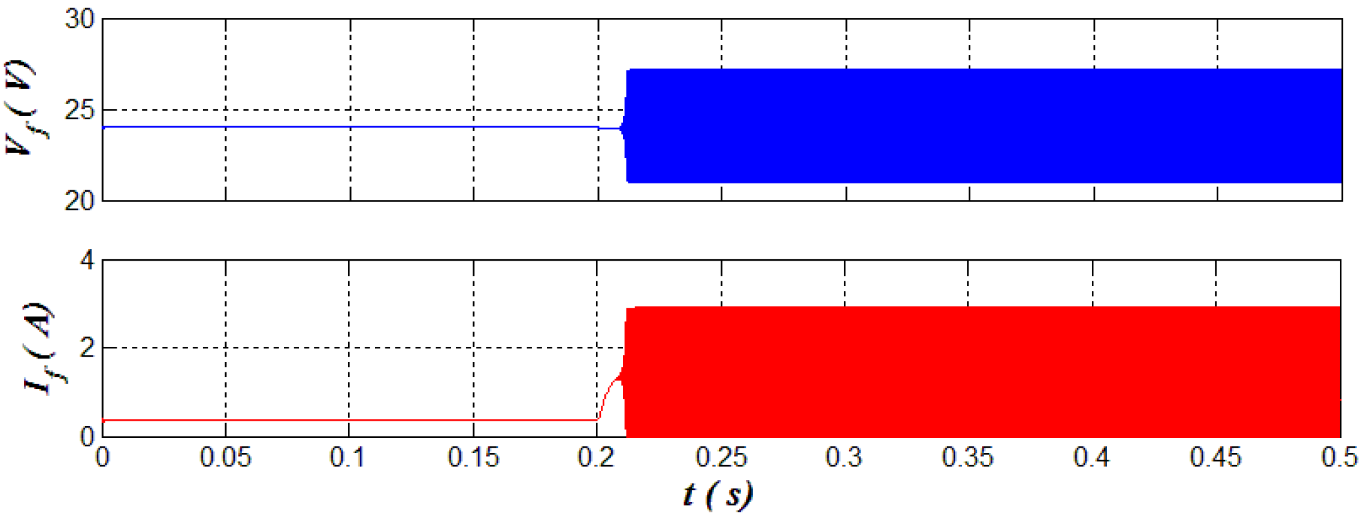
4. Simulation Results

In order to validate the proposed stabilizer design, simulations are carried out first using MATLAB with the parameters in Table 1. The simulation is performed firstly without stabilizer. As mentioned in the previous analysis, if the load power exceeds 25 W without the stabilizer, the system becomes unstable. In Figure 10, a load power of p = 9 W is applied to the system at t = 0 s. It can be seen from the figure that the system output voltage can stay stable. Then at t = 0.1 s, the load power is increased up to about 33 W. The simulation results show that the system becomes unstable. An oscillation occurs in the voltage as well as the current. This oscillation is dangerous to the whole system in practice and needs to be eliminated.
In order to verify the effectiveness of the proposed stabilizer, the simulation is conducted again with the presence of the stabilizer this time. As clearly seen in Figure 11, with the same power step (from 9 W to 33 W) the system remains stable. Thus, the proposed stabilizer design could efficiently stabilize the system without increasing the input filter capacitor value.

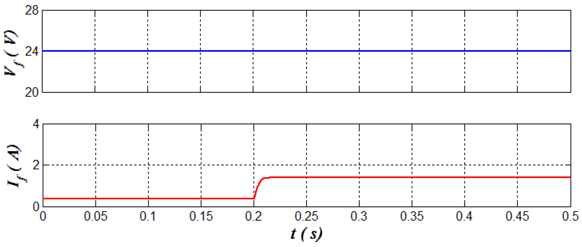
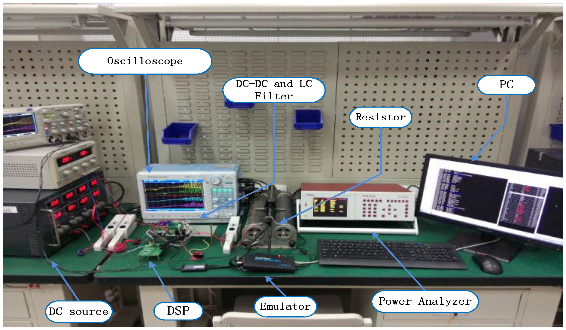
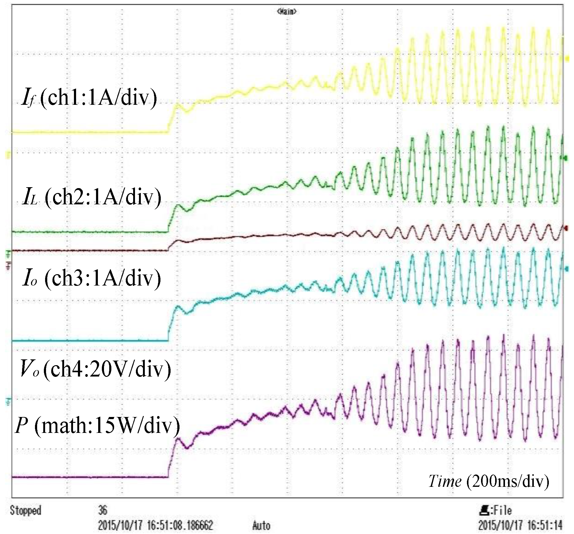
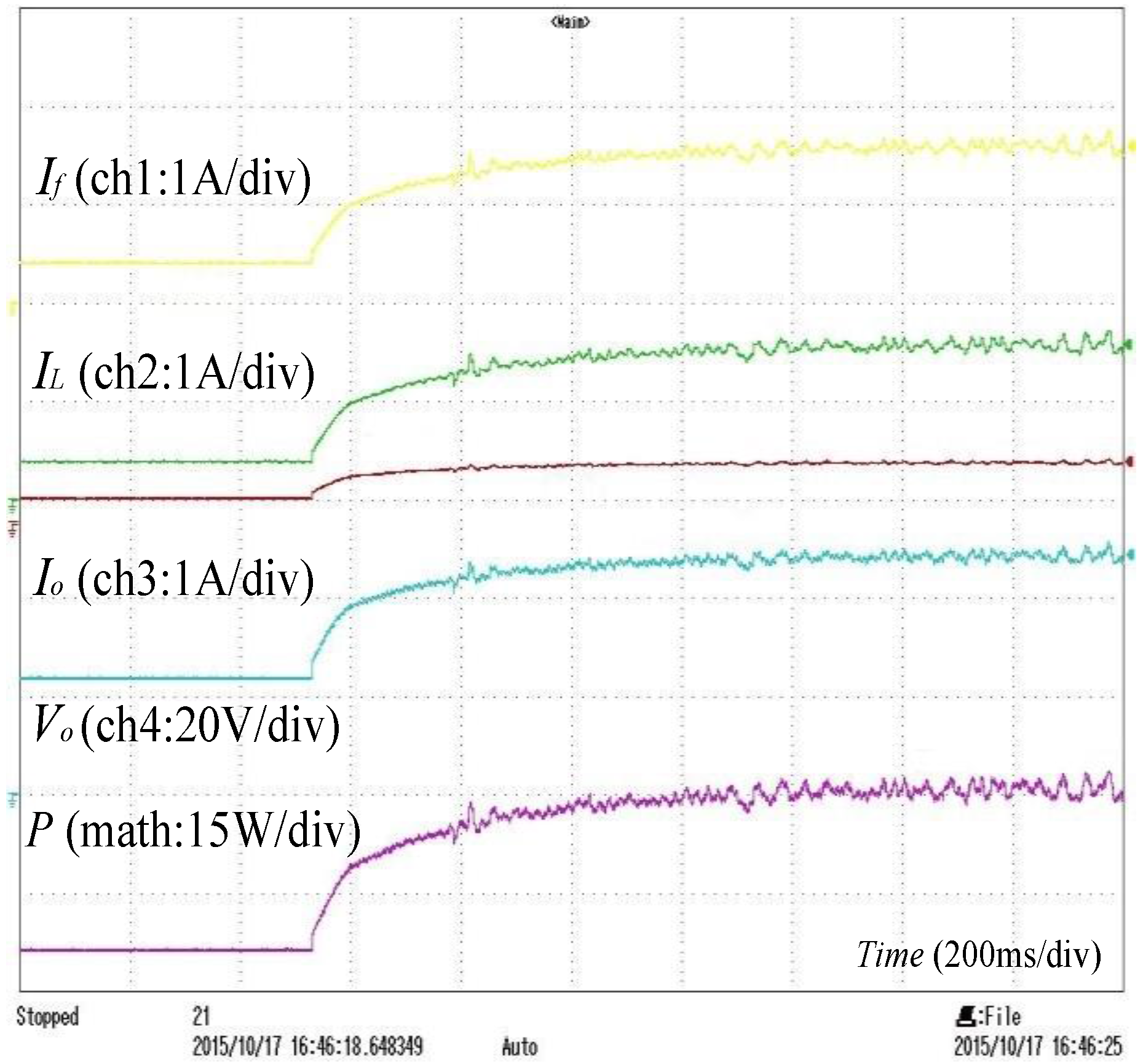
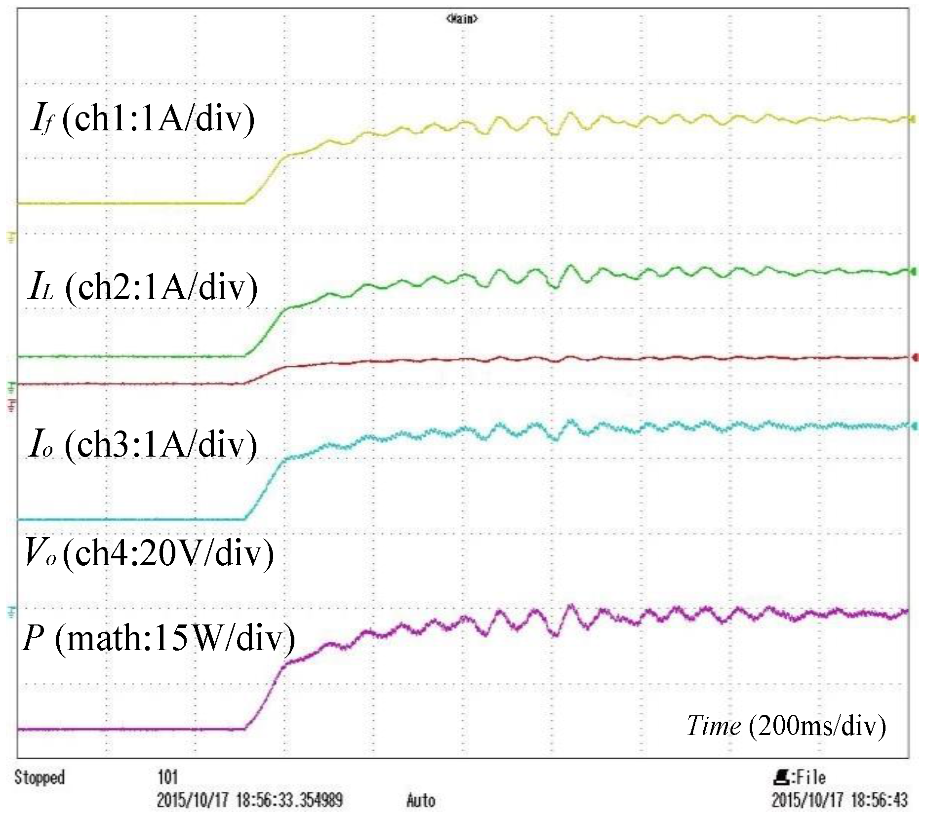
5. Experimental Results

In addition to the simulation, experiments are carried out to validate the performance of the proposed stabilizer approach. A test bench is built in the laboratory as shown in Figure 12. A DSP (TMS320F28035, Texas Instruments, Dallas, TX, USA) is used to implement different control loops and stabilizers to control the system. The sampling frequency of the DSP and the switching frequency of the converter are both set to 80 kHz. The parameters of the test bench are the same as given in Table 1. The current measurements are realized by a Hall current sensor and sampled by an oscilloscope (DL850, Yokogawa, Tokyo, Japan). The power is measured by a precision power analyzer (PPA5530, N4L, Leicester, UK). The DC voltage is generated by a laboratory scale dc power supply. The converter is connected through input LC filter to the dc link. A resistive load is connected to the boost converter output. The implemented program flow chart in the DSP is presented in Figure 13.
Initially, the stabilizer is switched off. The system is observed in steady state in Figure 14 for two different power stages: one with a small load power about 9 W in which the system is stable; and the other one with a higher load power about 33 W in which the system becomes unstable. In the latter case, voltage and current oscillations occur (instability). The second time, the same experimental scenario is performed with the action of stabilizer this time. As expected, the system remains stable during both power stages, as shown in Figure 15.
Additionally, Figure 16 presents the case when the stabilizer passes from enabled to disabled for a load power of 33 W. It can be seen clearly from the figure that the system lost its stability.
Furthermore, as discussed in the previous sections, a larger input filter capacitor could also increase the stability margin of the system. According to Figure 9, increasing the capacitor value from 10 µF to 150 µF can make the system remain stable for a power up to 33 W without adding the stabilizer. This experimental result is shown in Figure 17 and verifies the correctness of the conclusion of Figure 9.

6. Conclusions

In this paper, a novel stabilizer for a boost power converter system with a small input LC filter is proposed. This stabilizer is realized by measuring the input filter inductance current and designing a DSP-based digital stabilizer. The stability analysis is based on the linearized DC power converter system around the equilibrium point.
Compared with the traditional method, in on-board applications such as transportation, the proposed stabilizer could break the compromise between weight saving and stability. Compared to the methods in the literature, the proposed stabilizer does not change the original control structure and can solve the limitations of the sensor bandwidth.
Implementation of the proposed stabilizer can suppress the oscillations and stabilize the system. The performance of the dynamic response could be optimized. Moreover, it is shown that the stability power margin can be significantly increased. Simultaneously, this stabilizer permits one to reduce the weight and size of the system, which is important for transportation applications.
A mathematical model is established to analyze the stability and to demonstrate the effectiveness of the proposed stabilizer. The stability analysis has been verified by simulation and experimental results.

Acknowledgments

This work was supported by the Aeronautical Science Foundation of China under Grant2014ZC53037 and the Key Science and Technology Program of Shaanxi Province, China under Grant 2016GY-149.

Author Contributions

All authors have worked on this manuscript together and all authors have read and approved this manuscript. Shengzhao Pang is the corresponding author of this paper.

Conflicts of Interest

The authors declare no conflict of interest.

References

  1. Magne, P.; Nahid-Mobarakeh, B.; Pierfederici, S. Dynamic Consideration of DC Microgrids with Constant Power Loads and Active Damping System—A Design Method for Fault-Tolerant Stabilizing System. IEEE J. Emerg. Sel. Top. Power Electron. 2014, 2, 562–570. [Google Scholar] [CrossRef]
  2. Yang, N.; Paire, D.; Gao, F.; Miraoui, A.; Liu, W. Compensation of droop control using common load condition in DC microgrids to improve voltage regulation and load sharing. Int. J. Electr. Power Energy Syst. 2015, 64, 752–760. [Google Scholar] [CrossRef]
  3. Zadeh, M.K.; Roghayeh, G.-G.; Pierfederici, S.; Babak, N.-M.; Molinas, M. A discrete-time tool to analyze the stability of weakly filtered active front-end PWM converters. In Proceedings of the Transportation Electrification Conference and Expo (ITEC), Dearborn, MI, USA, 15–18 June 2014; pp. 1–7.
  4. Xing, L.; Feng, F.; Sun, J. Optimal damping of EMI filter input impedance. IEEE Trans. Ind. Appl. 2011, 47, 1432–1440. [Google Scholar] [CrossRef]
  5. Pang, S.; Huangfu, Y.; Guo, L.; Nahid-Mobarakeh, B. A Stability Method Using High-frequency Current Feed-forward Compensation for Boost Converter Systems. Proc. CSEE 2016, 20, 5616–5623. [Google Scholar]
  6. Saublet, L.-M.; Gavagsaz-Ghoachani, R.; Martin, J.-P. Asymptotic Stability Analysis of the Limit Cycle of a Cascaded DC–DC Converter Using Sampled Discrete-Time Modeling. IEEE Trans. Ind. Electron. 2016, 63, 2477–2487. [Google Scholar] [CrossRef]
  7. Jamshidpour, E.; Nahid-Mobarakeh, B.; Poure, P.; Pierfederici, S.; Meibody-Tabar, F.; Saadate, S. Distributed active resonance suppression in hybrid DC power systems under unbalanced load conditions. IEEE Trans. Power Electron. 2013, 28, 1833–1842. [Google Scholar] [CrossRef]
  8. Magne, P.; Nahid-Mobarakeh, B.; Pierfederici, S. DC-link voltage large signal stabilization and transient control using a virtual capacitor. In Proceedings of the Industry Applications Society Annual Meeting (IAS), Houston, TX, USA, 3–7 October 2010; pp. 1–8.
  9. Jamshidpour, E.; Nahid-Mobarakeh, B.; Poure, P.; Pierfederici, S.; Saadate, S. Distributed stabilization in DC hybrid power systems. In Proceedings of the Vehicle Power and Propulsion Conference (VPPC), Chicago, IL, USA, 6–9 September 2011; pp. 1–6.
  10. Middlebrook, R.D. Input Filter Considerations in Design and Application of Switching Regulators. In Proceedings of the Industry Applications Society Annual Meeting IAS, Chicago, IL, USA, 11–14 October 1976.
  11. Middlebrook, R. Design techniques for preventing input-filter oscillations in switched-mode regulators. In Proceedings of the Powercon, San Francisco, CA, USA, 4–6 May 1978; pp. A3.1–A3.16.
  12. Cespedes, M.; Xing, L.; Sun, J. Constant-power load system stabilization by passive damping. IEEE Trans. Power Electron. 2011, 26, 1832–1836. [Google Scholar] [CrossRef]
  13. Gavagsaz-Ghoachani, R.; Martin, J.; Pierfederici, S.; Nahid-Mobarakeh, B.; Davat, B. DC Power Networks with Very Low Capacitances for Transportation Systems: Dynamic Behavior Analysis. IEEE Trans. Power Electron. 2013, 28, 5865–5877. [Google Scholar] [CrossRef]
  14. Lee, W.-J.; Sul, S.-K. DC-link voltage stabilization for reduced DC-link capacitor inverter. IEEE Trans. Ind. Appl. 2014, 50, 404–414. [Google Scholar]
  15. Zadeh, M.K.; Amin, M.; Suul, J.A.; Molinas, M.; Fosso, O.B. Small-signal stability study of the Cigré DC grid test system with analysis of participation factors and parameter sensitivity of oscillatory modes. In Proceedings of the Power Systems Computation Conference (PSCC), Wroclaw, Poland, 18–22 August 2014; pp. 1–8.
  16. Kondratiev, I.; Santi, E.; Dougal, R.; Veselov, G. Synergetic control for DC–DC buck converters with constant power load. In Proceedings of the 35th Annual Power Electronics Specialists Conference, PESC, Aachen, Germany, 20–25 June 2004; pp. 3758–3764.
  17. Santi, E.; Li, D.; Monti, A. A geometric approach to large-signal stability of switching converters under sliding mode control and synergetic control. In Proceedings of the IEEE 36th Power Electronics Specialists Conference, Recife, Brazil, 12–18 June 2005; pp. 1389–1395.
  18. Saublet, L.-M.; Gavagsaz-Ghoachani, R.; Martin, J.-P.; Pierfederici, S.; Nahid-Mobarakeh, B.; Da Silva, J. Stability analysis of a tightly controlled load supplied by a DC-DC boost converter with a modified sliding mode controller. In Proceedings of the IEEE Transportation Electrification Conference and Expo (ITEC), Dearborn, MI, USA, 15–18 June 2014; pp. 1–6.
  19. Rivetta, C.H.; Emadi, A.; Williamson, G.; Jayabalan, R.; Fahimi, B. Analysis and control of a buck DC-DC converter operating with constant power load in sea and undersea vehicles. IEEE Trans. Ind. Appl. 2006, 42, 559–572. [Google Scholar] [CrossRef]
  20. Marx, D.; Pierfederici, S.; Nahid-Mobarakeh, B.; Davat, B. Contribution to determination of domain of attraction in power systems: Application to drives with input filter. In Proceedings of the Industry Applications Society Annual Meeting, Houston, TX, USA, 4–8 October 2009; pp. 1–8.
  21. Lu, X.; Sun, K.; Huang, L.; Guerrero, J.M.; Vasquez, J.C.; Xing, Y. Virtual impedance based stability improvement for DC microgrids with constant power loads. In Proceedings of the Energy Conversion Congress and Exposition (ECCE), Pittsburg, PA, USA, 14–18 September 2014; pp. 2670–2675.
  22. Wu, M.; Lu, D.D.-C. A Novel Stabilization Method of LC Input Filter with Constant Power Loads without Load Performance Compromise in DC Microgrids. IEEE Trans. Ind. Electron. 2015, 62, 4552–4562. [Google Scholar] [CrossRef]
  23. Mohamed, Y.A.-R.; Radwan, A.A.A.; Lee, T. Decoupled reference-voltage-based active DC-link stabilization for PMSM drives with tight-speed regulation. IEEE Trans. Ind. Electron. 2012, 59, 4523–4536. [Google Scholar] [CrossRef]
  24. Magne, P.; Nahid-Mobarakeh, B.; Pierfederici, S. General active global stabilization of multiloads DC-power networks. IEEE Trans. Power Electron. 2012, 27, 1788–1798. [Google Scholar] [CrossRef]
  25. Thounthong, P.; Chunkag, V.; Sethakul, P.; Sikkabut, S.; Pierfederici, S.; Davat, B. Energy management of fuel cell/solar cell/supercapacitor hybrid power source. J. Power Sources 2011, 196, 313–324. [Google Scholar] [CrossRef]
Figure 1. Topological structure of the studied system.
Energies 09 00934 g001
Figure 2. Command scheme of the studied system.
Energies 09 00934 g002
Figure 3. Frequency response of compensated loop gain with current controller and stabilizer.
Energies 09 00934 g003
Figure 4. Frequency response of compensated loop gain with energy controller, current controller and stabilizer.
Energies 09 00934 g004
Figure 5. Bode diagram of the response peaks without the stabilizer.
Energies 09 00934 g005
Figure 6. Bode diagram of the response peaks with the stabilizer.
Energies 09 00934 g006
Figure 7. System stability limit.
Energies 09 00934 g007
Figure 8. Stable operating points (blue circles) and unstable operating points (red crosses) with Cf = 10 µF.
Energies 09 00934 g008
Figure 9. Stable operating points (blue circles) and unstable operating points (red crosses) with Kstab = 0.
Energies 09 00934 g009
Figure 10. Simulation results when load references step from 9 W to 33 W without the stabilizer.
Energies 09 00934 g010
Figure 11. Simulation results when load references step from 9 W to 33 W with the stabilizer.
Energies 09 00934 g011
Figure 12. Experimental bench.
Energies 09 00934 g012
Figure 13. Program flow chart.
Energies 09 00934 g013
Figure 14. Experimental system response to a load references step from 9 W to 33 W without the stabilizer.
Energies 09 00934 g014
Figure 15. Experimental system response to a load references step from 9 W to 33 W with the stabilizer.
Energies 09 00934 g015
Figure 16. Experimental system response when the system loses the stabilizer.
Energies 09 00934 g016
Figure 17. Experimental system response to a load references step from 9 W to 33 W without the stabilizer, when the capacitor of the input filter is 150 µF.
Energies 09 00934 g017
Table 1. System Parameters.
ParameterSymbolQuantity
Input Filter Parameters
Filter capacitanceCf10 μ F
Filter inductanceLf43 μ H
Filter inductor resistancerf0.02 Ω
DC-DC Converter Parameters
Boost capacitanceC10 μ F
Boost inductanceL100 μ H
Boost inductor resistancer0.04 Ω
Source and Load Parameters
Source input voltageVg24 V
Load ResistanceR70 Ω
Stabilizer Parameters
Stabilizer GainKstab−0.8
High-pass filter pulsationωn16,075 rad/s

