Article

Simple Design Approach for Low Torque Ripple and High Output Torque Synchronous Reluctance Motors

by
Mohamed Nabil Fathy Ibrahim
1,2,*,
Peter Sergeant
1,3 and
Essam Rashad
4
1
Department of Electrical Energy, Systems and Automation, Ghent University, 9000 Ghent, Belgium
2
Electrical Engineering Department, Kafrelshiekh University, 33511 Kafr El Sheikh, Egypt
3
Flanders Make, the Strategic Research Center for the Manufacturing Industry, B-8500 Kortrijk, Belgium
4
Electrical Power and Machines Department, Tanta University, 31527 Tanta, Egypt
*
Author to whom correspondence should be addressed.
Energies 2016, 9(11), 942; https://doi.org/10.3390/en9110942
Submission received: 11 September 2016 / Revised: 27 October 2016 / Accepted: 7 November 2016 / Published: 11 November 2016
(This article belongs to the Special Issue Electric Machines and Drives for Renewable Energy Harvesting)

Abstract

:
The rotor design of Synchronous Reluctance Motors (SynRMs) has a large effect on their efficiency, torque density and torque ripple. In order to achieve a good compromise between these three goals, an optimized rotor geometry is necessary. A finite element method (FEM) is a good tool for the optimization. However, the computation time is an obstacle as there are many geometrical parameters to be optimized. The flux-barrier widths and angles are the two most crucial parameters for the SynRM output torque and torque ripple. This paper proposes an easy-to-use set of parametrized equations to select appropriate values for these two rotor parameters. With these equations, the reader can design a SynRM of distributed windings with a low torque ripple and with a better average torque. The methodology is valid for a wide range of SynRMs. To check the validity of the proposed equations, the sensitivity analysis for the variation of these two parameters on the SynRM torque and torque ripple is carried out. In addition, the analysis in this paper gives insight into the behavior of the machine as a function of these two parameters. Furthermore, the torque and torque ripple of SynRMs having a rotor with three, four and five flux-barriers are compared with three literature approaches. The comparison shows that the proposed equations are effective in choosing the flux-barrier angles and widths for low torque ripple and better average torque. Experimental results have been obtained to confirm the FEM results and to validate the methodology for choosing the rotor parameters.

1. Introduction

Nowadays, there is a great interest in the efficiency and cost of electrical machines because the electric motors consume about 40%–45% of the produced electricity and about 70% of industrial electricity [1]. In addition, the cost of rare-earth magnets and their marketing stability are unpredictable. This makes reluctance machines an attractive alternative compared to other types of electric machines [1,2].
Synchronous reluctance motors (SynRMs) with flux-barrier rotors have a robust and simple structure. Moreover, their rotors have no cages, windings and permanent magnets. The absence of copper losses in the rotor reduces the temperature rise. Hence, they can be good competitors compared to permanent magnet synchronous motors (PMSMs) and induction motors (IMs) [3,4,5].
The SynRM performance (output torque, torque ripple, power factor and efficiency) depends mainly on the ratio between the direct and quadrature axis inductances (Ld, Lq). For a given stator design, this ratio (Ld/Lq) is the outcome of the geometrical parameters of the flux-barrier layers in the rotor. In addition, the magnetic materials and the stator winding type are other possible ways to improve the saliency ratio, hence the SynRM performance [5,6,7,8].
It is well known that to obtain an optimal SynRM performance, choosing the flux-barrier parameters of the SynRM rotor is very complex due to several parameters. Therefore, an optimization technique is necessary to maximize the machine output torque and to minimize the torque ripple. There are two possibilities to couple the optimized technique with the SynRM model to calculate the output torque, power factor, torque ripple and efficiency. The first possibility is to make a parameterized analytical approach for the SynRM, in which all the stator and rotor parameters as well the magnetic material saturation behavior and rotor position dependence have to be included [9,10,11]. The second possibility is to build the SynRM model using the finite element method (FEM) [4,8]. The latter model is much more simple and accurate in predicting the SynRM performance compared to the analytical one. However, it takes a very huge computation time [12]. Another option, in order to reduce the FEM computation time, is to use the analytical approach coupled to the FEM to obtain optimized flux-barrier parameters; here, a FEM model with the optimized parameter set of the analytical approach is built for refinement [13]. This is an efficient method but evidently requires the effort to develop two models.
Therefore, in the literature, a number of papers presented some simple approaches and/or parametrized equations for a better SynRM rotor to be used in the optimization with FEM [14,15,16,17]. There are several rotor parameters as shown in Figure 1. The impact of these parameters on the saliency ratio (Ld/Lq) of the SynRM is investigated in [18]. It is evident that the flux-barrier widths and angles have a huge influence on the SynRM output torque and torque ripple, respectively. Therefore, a great interest for finding an easy method to choose these two parameters was considered [15].
In [14], a general formula was proposed for selecting the number of flux-barrier layers and for determining the flux-barrier angles for any number of stator slots to minimize the torque ripple. This method is very simple and effective. However, the resulting torque ripple is still a bit high, around 26% as proved in [19]. In [15], simple methods to choose the flux-barrier angles and widths were suggested. However, these methods give a rough estimation only; afterwards, a FEM sensitivity analysis is still required to fine-tune the value of angle β to obtain a low torque ripple. Furthermore, the authors of [16] combined both methods of [14] and [15] and added additional factors to make a generalized formula. The additional factors are the number of stator and rotor slots as well the stator and rotor slot openings. Nevertheless, the torque ripple is still high and for some cases is higher than both [14] and [15]. Moreover, an interesting work was presented in [17] to choose a preliminary design for the flux-barrier widths. However, the influence of different stator slots is not considered. Therefore, further research is needed to find out a simple method to choose the preliminarily flux-barrier angles and widths of the SynRM for low torque ripple and better average torque.
In this paper, easy-to-use simple equations for choosing the flux-barrier angle and the width of SynRMs of distributed windings, for low torque ripple and better average torque, are proposed. The proposed equations are carried out on several layers of flux-barriers and they can produce a good design to be used in the optimization. This indeed will reduce the computation time of the optimization process. In addition, a sensitivity analysis for the variation of flux-barrier angles and widths on the SynRM torque ripple and average torque is done. The simulation results of the FEM have been validated by measurements.

2. Selection of SynRM Flux-Barrier Angles and Widths

As said, the two crucial rotor design parameters of the SynRM are the flux-barrier angle and width. This is because the flux-barrier angles have a huge influence on the SynRM torque ripple, and the flux-barrier widths have a strong effect on the SynRM average torque [17]. In the following paragraph, three existing methods to choose the flux-barrier angles and one existing method for the flux-barrier width are compared with a new method. The accuracy of the methods is benchmarked for several machines in Section 3.

2.1. Flux-Barrier Angle Selection

In literature, three methods were presented to choose the flux-barrier angles in order to obtain a preliminarily design for the SynRM with low torque ripple [14,15,16,17]. These methods will be described as follows:
(1)
The first method given in [14] simply correlates the number of stator slots ns and rotor slots nr per pole pair as follows:
n r = n s ± 4
where the rotor pitch angle (γ) is constant between the flux-barriers as sketched in Figure 1a. In this method, if the nr is selected so that the spatial harmonics nr ± 1 and ns ± 1 are of a different order, this results in a strong reduction in the pulsation of the stator magnetomotive force (MMF). Therefore, nr and ns must be even positive numbers. In addition, the selection between ±4 is a matter of discussion. However, it is proved in [14] that +4 in Equation (1) gives a lower torque ripple machine than −4.
(2)
The second method was investigated in [15], and it is a refinement of the first method. The authors introduced an additional angle β (see Figure 1b) to generalize [14]. This angle β is used to control the value of the rotor slot pitch angle γ as follows:
γ = π 2 P β n l a y e r + 0.5
where nlayer is the number of flux-barrier layers and P is the number of pole pairs. In this method, to minimize the torque ripple for any number of stator slots and flux-barrier angles, FEM sensitivity analysis is necessary on the angle β.
(3)
The third method was presented in [16] by assuming that β = γ/2 in (2). In addition, they added an additional factor N, which is equal to ns/nr to generalize the method for different numbers of stator and rotor slots as follows:
γ = π 2 P N ( n l a y e r + 1 )
In this method, the factor N is proposed in the denominator of Equation (3) in order to have a smaller pitch angle γ for a higher number of stator slots. This is because the slot pitch angle is inversely proportional with the factor N.
More literature is published about the flux-barrier design, allowing for improvement of the SynRM torque ripple. The previous methods for selecting the flux-barrier angles use equally spaced rotor slots (see Figure 1) like that of the stator slots distribution. Nevertheless, asymmetrical rotor slot angles can also be used as investigated in [20]. It is proved in the literature that the torque ripple of SynRM can be reduced by selecting unequally spaced rotor slots [21]. In addition, a method to reduce the torque ripple of SynRMs is given in [17]; the flux-barrier angles (see red circles in Figure 1b) should be selected such that when the first end (x) moves towards the opening of the corresponding stator slot, the second end (y) moves away from the opening of the corresponding stator slot opening at the same time. This results in positive and negative torque pulsations during the motor operation. Eventually, the positive and negative torque pulsations may cancel each other, resulting in a reduced torque ripple for the SynRM.
Based on [14,22,23], we can propose a new approach that can produce a preliminary SynRM design with low torque ripple and better average torque by considering the following steps:
(a)
the number of stator slots should be maximized as much as possible;
(b)
the number of rotor layers can be selected based on [14] or the following Table 1 given in [22,23].
Then, to choose the flux-barriers angles, we propose an angle β (see Figure 2) and use it to control the rotor slot pitch angle γ. Here, the slot pitch angle of the first flux-barrier layer closest to the d-axis (see Figure 2) is not equal to the pitch angles between the other flux-barrier layers. This results in two easy-to-use parametrized equations for choosing the flux-barrier angles. The proposed method is generalized for any number of flux-barrier layers and poles as follows:
β = π 4 P n l a y e r
γ = ( 1 n l a y e r ) ( π 2 P 2 β )
where nlayer is the number of flux-barrier layers, γ is the rotor slot pitch angle and β is an angle as sketched in Figure 2. The proposed method considers that the rotor and stator slot openings are identical because this helps in reducing the torque ripple of the SynRM [17].

2.2. Flux-Barrier Width Selection

In order to choose the flux-barrier width of the SynRM rotor, the authors of the second method, which was mentioned before, presented an easy equation as given by [15,17]:
W b t = K w q × W i t
where Wbt is the total flux-barrier width (Wb1 + Wb2 + Wb3 in Figure 2) and Wit is the total iron width in the q-axis direction. Note that the width of the different flux-barriers is equal. They proved by several FEM simulations that the optimum value for Kwq is around 0.6–0.7.
It is evident that Equation (6) does not consider the effect of the stator teeth width. Therefore, we can propose the following simple equation in which the effect of the stator teeth width is included:
W b = W t q W t h ( n l a y e r + 1 ) n l a y e r
where Wb and Wth are the width of the flux-barrier and the stator teeth, respectively; Wtq is the total width of the iron in the q-axis direction and nlayer is the number of flux-barrier layers.
The total width of the flux-barrier Wtq is computed by:
W t q = D r i D s h 2
where Dri and Dsh are the rotor inner diameter and the shaft diameter, respectively. The width of all the flux-barriers is equal as in Equation (6). In addition, the width of the rotor iron segment (S1, S2, S3 and S4 in Figure 1a) is equal to the stator teeth width.

3. Accuracy of the Easy-to-Use Equations

In order to compare the previous methods with the method proposed in this paper, first, a sensitivity analysis for the influence of the variation of the flux-barrier angles and widths on the SynRM average torque and torque ripple is done. This analysis aims to show an insight about the effect of the different flux-barrier angles and widths on the average torque and torque ripple.
Let us refer to a SynRM geometry with a 10 kW, four-poles and 36 stator slots with the geometrical parameters given in Table A1 (Appendix) [5]. The stator has three phase star connected distributed windings, with 15 turns/slot connected in two parallel groups. The stator slot area is 100 mm2 and the stator slot opening is 2.8 mm. More details about the stator are reported in Figure A1 and Table A1 in the Appendix section. From Table 1, as the number of stator slots is 36, three flux-barriers per pole are then considered for the sensitivity analysis [14,22,23]. However, the proposed method is also validated for other numbers of barriers. There are several shapes for the flux-barriers [24]. The shape of Figure 2 is employed in which pb, Wb, Lb and θb are the flux-barrier position, width, length and angle, respectively. The detailed values of these parameters are listed in Table A1 (Appendix).
For the sensitivity analysis of the SynRM, the stator, air gap and rotor dimensions shown in Figure 2 are fixed and equal to the reference values given in Table A1 (Appendix). Only the rotor flux-barrier angles θbi or widths Wbi have been changed, with i = 1:3. As there are three flux-barriers, this leads to a three-dimensional parameter space, e.g., in the case of flux-barrier angles, we obtain functions of θb1, θb2 and θb3.
The characteristics of the SynRM are computed using 2D-FEM in which only one pole of the considered four-pole SynRM needs to be modelled. Sinusoidal currents are injected in the windings of the machine at the rated speed (6000 r/min). The stator current is the rated value (22 A) at a current angle α = 56.5°. The current angle (α) is the angle of the stator current space vector with respect to the d-axis of the motor as shown in [25]. The flux paths for two different rotor positions are reported in Figure 3.

3.1. Effect of the Flux-Barrier Angles, θbi

The three flux-barrier angles θb1, θb2 and θb3, shown in Figure 2, are measured in degrees from the d-axis to the center of the flux-barrier. The sensitivity analysis is done for a wide range of flux-barrier angles. Here, the results focus on the most important range listed in Table 2. As mentioned before, all of the other rotor variables are kept constant and equal to the reference values given in Table A1 (Appendix). Then, the SynRM is solved by FEM and the average torque and torque ripple can be obtained.
Figure 4 shows the variation of the SynRM average torque for different flux-barrier angles at the rated conditions. The maximum and minimum torque values, within the considered range of flux-barrier angles, are 16.08 N.m and 14.61 N.m (about 10.04% difference, compared to the minimum value), respectively. On the one hand, when looking to, e.g., the top right subfigure, the average torque of the SynRM decreases with increasing both θb2 and θb3. In addition, when comparing the four subfigures (having the same color scale), the average torque increases with increasing θb1 till approximately 7.5 degrees and then decreases again. In fact, the variation of the average torque with the flux-barrier angles has two main reasons: (1) the variation of the d-axis flux path area and (2) the variation of the area and the magnetic saturation level of the flux-barrier ribs (see Figure 2), which has a direct effect on the q-axis inductance value. Clearly, there is an optimal value of the flux-barrier angles that realizes the maximum torque: see subfigures for θb1 = 7.5° and θb1 = 8.75°.
Figure 5 describes the torque ripple percentage of the SynRM due to the variation of the flux-barrier angles at the rated conditions. The maximum and the minimum torque ripple values are 66.9% and 12.3% (about four times the minimum value), respectively. The difference on the torque ripple is enormous. It is a result of the interaction between the spatial harmonics of the magnetomotive force (MMF) of the stator currents and the rotor geometry, in particular the flux-barrier angles. It is evident that for the flux-barrier angles that are corresponding to the stator slots openings, θb1 = 10°, θb2 = 20° and θb3 = 30°, the SynRM torque ripple is very high—more than 60%. In addition, with moving the flux-barrier angles away from the stator slots openings, the torque ripple of SynRM reduces to a minimum value Ⓜ in Figure 5. This can be seen for θb1 = 7.5°, θb2 = 17° and θb3 = 27°.
The results of the proposed method, given by Equations (4) and (5), and the aforementioned three methods, given by Equations (1)–(3) are allocated in Figure 4 and Figure 5. The abbreviations Ⓟ, ①, ② and ③ refer to the proposed, first, second and third methods, respectively. Note that only the flux-barrier angles are different between the several methods, and the other geometrical parameters are constant and equal to the values shown in Figure A1 and Table A1 (Appendix). Besides Figure 4 and Figure 5, the output torque and torque ripple of the SynRM designs based on the different methods are listed in Table 3. The torque and torque ripple based on both methods ① and ② are approximately assigned in Figure 4 and Figure 5 at θb1 = 5°. In addition, the torque and torque ripple based on the method ③ cannot be assigned in Figure 4 and Figure 5 because the flux-barrier angles based on this method are out of the considered range. However, their values are mentioned in Table 3 and lead to a SynRM design with a high torque ripple value. From Figure 4, Figure 5 and Table 3, it is clear that the proposed method Ⓟ gives a SynRM design with the lowest torque ripple of about 12.63%. On the other hand, the average torque based on the proposed method Ⓟ is much better, compared to the others. It is important to point out that the exact values of torque and torque ripple mentioned in Table 3 may not be indicated in Figure 4 and Figure 5 because the contour plots show only the trends of the variation of the parameters. In addition, for the results shown in Figure 4 and Figure 5, the flux-barrier end arc is equal to half of the flux barrier width, given in Table A1, while for the proposed and the existing methods, the flux-barrier end arc is equal to the slot opening. This indeed will have an influence on the average torque and torque ripple.
The proposed method Ⓟ is not only validated for a SynRM rotor with three flux-barrier layers, but also for four and five flux-barrier layers and compared with the three existing methods ①, ② and ③. This is to show its effectiveness in both odd and even number of flux-barrier layers. It is important to highlight that the comparison between the different methods is done for similar electromagnetic and geometrical parameters. Only the flux-barrier angles are chosen based on the method. In Table 4, it is clear that the proposed method Ⓟ gives a SynRM of four barriers rotor with a torque ripple of 25.45% which is lower than both methods ① and ③ and a bit more than method ②. Note that in case of a four flux-barrier rotor, the method ① is not valid. Therefore, it gives a SynRM design with a very high torque ripple—about 71.6%. The average torque of the SynRM based on the proposed method Ⓟ is much better than the others. In Table 5, it is obvious that the proposed method Ⓟ gives a SynRM with the lowest torque ripple and highest average torque compared to the existing methods. The torque ripple is about 20.30% based on the proposed method Ⓟ.
From Table 3, Table 4 and Table 5, it is clear that the proposed method, given by Equations (5) and (6), gives better results than the existing methods, given by Equations (1)–(3), for the different number of flux-barrier layers.

3.2. Effect of the Flux-Barrier Widths, Wbi

The flux-barrier widths Wb1, Wb2 and Wb3 are defined as shown in Figure 2. The sensitivity analysis is done for a wide range of flux-barriers widths. Here, the results for the most important range of Wb1, Wb2 and Wb3 listed in Table 6, is shown. The flux-barrier angles are selected based on the proposed method, and, therefore, their values are θb1 = 7.5°, θb2 = 17.5° and θb3 = 27.5°. All of the other rotor parameters are kept constant and equal to their value in the reference design given in Table A1 (Appendix).
Figure 6 shows the variation of the SynRM average torque for different flux-barrier widths at rated conditions. The computed maximum and minimum torque values are 16.06 N.m and 12.21 N.m (about 31.5% difference, compared to the minimum value), respectively. It is evident that, in general, the SynRM torque increases with increasing flux-barrier widths Wb1, Wb2 and Wb3. This is mainly due to the increasing q-axis magnetic reluctance, and, hence, decreasing q-axis inductance. In addition, the d-axis flux path area decreases, and, therefore, the d-axis inductance decreases a bit. However, the effect on the q-axis is much stronger so that the saliency ratio increases, and, hence, the torque increases too with increasing flux-barrier widths. It can be deduced that the variation of Wb1 has a much higher effect on the SynRM torque compared to the variation of both Wb2 and Wb3.
Based on the proposed method given by Equations (7) and (8) for selecting the flux-barrier width, the values of Wb1, Wb2 and Wb3 are equal to 5.54 mm. On the other hand, based on the second method, given by Equation (6), the values of Wb1, Wb2 and Wb3 are equal too but their values are 4.60 mm when Kwq = 0.65 in Equation (6). The torque of the SynRM with a three flux-barrier rotor is assigned with red circles in Figure 6 with approximating Wb1 to 5 mm. It is obvious that the SynRM torque based on the proposed method is better than the existing method.
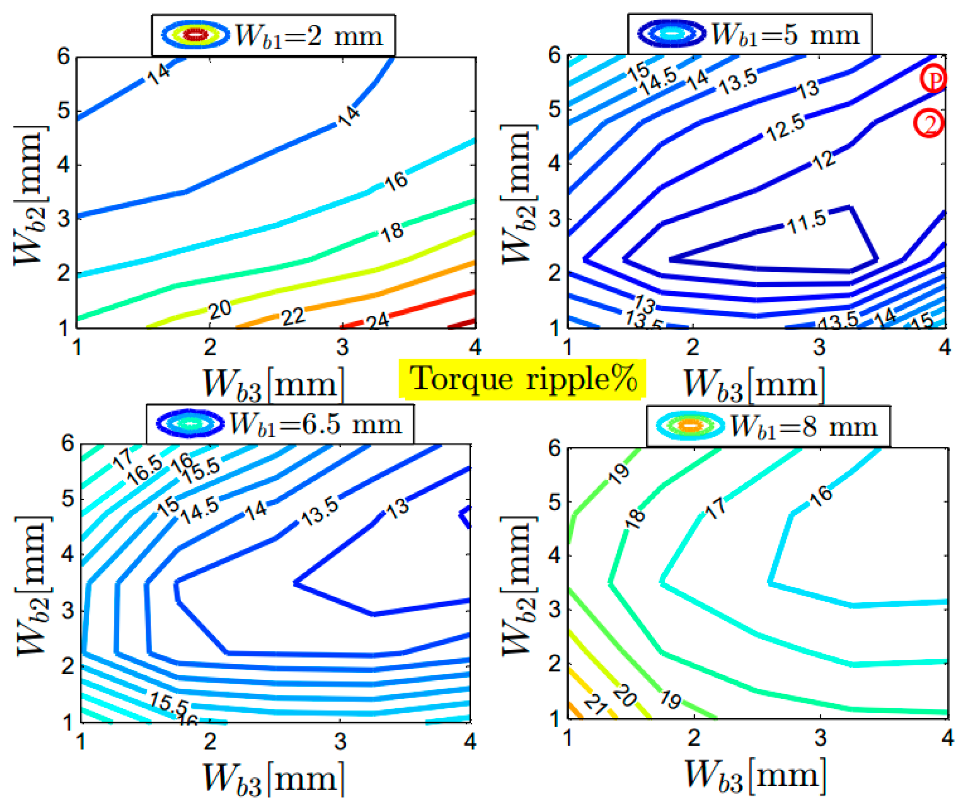
Figure 7 displays the torque ripple percentage due to the variation of the flux-barrier widths at the rated conditions. The maximum and the minimum torque ripple percentage values are 26.52% and 10.50% (about 152.5% difference, compared to the minimum value), respectively. The difference on the torque ripple is large and can be explained in the same way as in Section 3.1. An important conclusion here is that the torque ripple seems to remain very low regardless of the choice of the barrier width parameters. In addition, the torque ripple values based on the proposed and second method are assigned in Figure 7 with red circles. It is evident that both methods give approximately a similar torque ripple value. This is definitely because the flux-barrier angles are similar.

3.3. Comparison with the Optimal Rotor

To check how far the output torque and torque ripple of the SynRM design based on the proposed method differs from the optimal one, the conventional Latin hypercube optimized technique is employed for all the rotor parameters shown in Figure 2 [26]. The constraints on the rotor geometrical parameters (in total twelve) shown in Figure 2 are assumed to consider the whole possible range of variations. This optimization technique is coupled with FEM and the aforementioned stator is used. The target function is to obtain an optimized rotor design that is a compromise between a maximum average output torque and a minimum torque ripple not more than 10%. The both rotors contain three flux-barrier layers per pole. The resulting average torque and torque ripple of the SynRM with the optimal rotor design are about 17.85 N.m and 10%, respectively, as seen in Figure 8, compared to 16.65 N.m and 11.5% for the proposed method. This means that the design of the flux-barrier angles and widths based on the proposed method is close to the optimal choice.

4. Experimental Validation

For the validation of the proposed work and the FEM analysis presented in this paper, the experimental setup shown in Figure 9 is built. A SynRM prototype with the geometrical parameters listed in Table A1 is manufactured. This prototype is not the optimal one. The SynRM is loaded by an induction motor, which is controlled by a separate inverter. A torque sensor is mounted on the shaft between the two motors to measure the produced torque. The electrical variables (voltage, current, power) are measured using a three-phase power analyzer (Tektronix PA4000, Tektronix, Beaverton, OR, USA).
Because the SynRM performance (torque, power factor, and efficiency) depends mainly on the ratio between the direct and quadrature axis inductances (Ld, Lq), it is important to report the computed, by FEM, and the measured inductances here. The inductances of the SynRM (Ld(Id,0), Lq(0,Iq)) are measured by using the conventional standstill VI method given in [27]. For accurate computation for the inductances, the end winding effect has been included based on the relations given in [28]. The FEM simulated and measured dq-axis inductances of the SynRM are shown by Figure 10. There is good matching between the simulated and experimental results. However, the low difference between the two curves is due to different reasons: the cutting and punching effects on the steel properties, the manufacturing tolerance and the measurement error.
In order to obtain the measurements of the SynRM average torque and efficiency, field oriented control based on space vector pulse width modulation is implemented on a dSPACE1103 platform. The measured and the FEM simulated validation results have been obtained at 2000 rpm and (2/3) of rated current.
Figure 11 shows the FEM computed and the measured output torque of the SynRM. There is a good correspondence between the simulated and the measured values. The computed and the measured efficiency of the SynRM are reported in Figure 12. The same tendency between the results can be noticed. However, the simulated efficiency is higher than the experimental results due to various reasons. In the experimental test, the SynRM is supplied from a space vector pulse width modulated (SVPWM) inverter in contrast to the simulation, which is supplied from a sinusoidal supply. The PWM losses and mechanical losses are included in the measured efficiency and not included in the computed efficiency.

5. Conclusions

This paper has presented a simple method (parametrized equations) for choosing the two most crucial rotor parameters for synchronous reluctance motors (SynRMs) with conventional distributed windings. The two rotor parameters are the flux-barrier angles and widths. The proposed approach is compared to three existing methods in the literature. The comparison is done for a fixed machine stator with a different number of flux-barrier layers in the rotor, i.e., three, four and five per pole and for the same conditions. It is proved that the proposed method is effective in choosing the flux-barrier angles and widths of the SynRM interms output torque and torque ripple. The SynRM torque ripple and average torque based on the proposed method are better than the considered literature methods. This results in a good SynRM design as a proposed candidate for the optimization technique, which will reduce the required computation time.
Moreover, a sensitivity analysis for the variation of the aforementioned two parameters on the SynRM average torque and torque ripple is carried out on three flux-barrier rotors. It is shown that, for the different flux-barrier angles, the SynRM torque ripple varies from 12.3% to 66.9% for the considered range: about four times different compared to the minimum value. The average torque varies only from 14.61 to 16.08 N.m—about a 10% difference. In addition, for the different flux-barrier widths, the SynRM average torque varies from 12.21 N.m to 16.06 N.m—about a 31.5% difference compared to the minimum value. The torque ripple of the SynRM varies only from about 10.5% to 26.52%, which is rather low.
Finally, measurements are considered to validate the computed FEM results and the proposed methods.

Acknowledgments

The authors acknowledge the Egyptian Ministry of Higher Education (Cultural Affairs and Missions Sector) and the Special Research Fund of Ghent University (BOF) for the financial support during this work.

Author Contributions

All the authors contributed substantially to the work presented. Mohamed Nabil Fathy Ibrahim did the simulation and experimental works. In addition, he wrote the paper. Peter Sergeant gave a conceptual approach and provided comments at all the stages of the simulation and experimental works. Peter Sergeant and Essam Rashad revised the manuscript.

Conflicts of Interest

The authors declare no conflict of interest.

Appendix A

Figure A1. Stator slot and teeth dimensions in mm.
Energies 09 00942 g013
Table A1. Prototype SynRM Parameters.
ParameterValueParameterValue
Flux-barrier/pole3Rotor shaft diameter35 mm
Air gap length0.3 mmAxial length140 mm
Number of phases3Rated frequency200 Hz
Number of stator slots/poles36/4Rated speed6000 RPM
Stator outer/inner diameter180/ 110 mmRated current22 A
Rotor outer diameter109.4 mmMaterial typeM400-50 A
θb1,θb2 and θb37.5°, 20.5°, and 33.5°Wb1,Wb2 and Wb36, 4 and 3 mm
Lb1, Lb2 and Lb325, 19 and 12 mmpb1, pb2 and pb323.5, 36 and 46 mm

References

  1. De Almeida, A.T.; Ferreira, F.J.T.E.; Duarte, A.Q. Technical and economical considerations on super high-efficiency three-phasemotors. IEEE. Trans. Ind. Appl. 2014, 50, 1274–1285. [Google Scholar] [CrossRef]
  2. Huang, H.; Hu, Y.S.; Xiao, Y.; Lyu, H. Research of parameters and anti de magnetization of rare-earth-less permanent magnet-assisted synchronous reluctance motor. IEEE Trans. Magn. 2015, 51, 8112504. [Google Scholar] [CrossRef]
  3. Wang, Y.; Niu, S.; Fu, W. Electromagnetic performance analysis of novel flux-relatable permanent magnet machines for wide constant-power speed range operation. Energies 2015, 8, 13971–13984. [Google Scholar] [CrossRef]
  4. Nashiki, M.; Satake, A.; Kawai, Y.; Yokochi, T.; Okuma, S. A new flux-barrier-type reluctance motor with a slit rotor. IEEE Trans. Ind. Electron. 1999, 46, 1199–1206. [Google Scholar] [CrossRef]
  5. Ibrahim, M.N.; Sergeant, P.; Rashad, E.M. Synchronous reluctance motors performance based on different electrical steel grades. IEEE Trans. Magn. 2015, 51, 7403304. [Google Scholar] [CrossRef]
  6. Liang, P.; Pei, Y.; Chai, F.; Zhao, K. Analytical calculation of d- and q-axis inductance for interior permanent magnet motors based on winding function theory. Energies 2016, 9, 580. [Google Scholar] [CrossRef]
  7. Sato, S.; Sato, T.; Igarashi, H. Topology optimization of synchronous reluctance motor using normalized gaussian network. IEEE Trans. Magn. 2015, 51, 8200904. [Google Scholar] [CrossRef]
  8. Lee, J.H.; Lee, I.K.; Cho, Y.H.; Yun, T.W. Characteristics analysis and optimum design of anisotropy rotor synchronous reluctance motor using coupled finite element method and response surface methodology. IEEE Trans. Magn. 2009, 45, 4696–4699. [Google Scholar] [CrossRef]
  9. Bianchi, N.; Chalmers, B.J. Axially laminated reluctance motor: Analytical and finite-element methods for magnetic analysis. IEEE Trans. Magn. 2002, 38, 239–245. [Google Scholar] [CrossRef]
  10. Prieto, D.; Dessante, P.; Vannier, J.C.; Dagusé, B.; Jannot, X.; Saint-Michel, J. Multi-physic analytical model for a saturated permanent magnet assisted synchronous reluctance motor. IET Electr. Power Appl. 2016, 10, 356–367. [Google Scholar] [CrossRef]
  11. Mohammadi, M.H.; Rahman, T.; Silva, R.; Li, M.; Lowther, D.A. A computationally efficient algorithm for rotor design optimization of synchronous reluctance machines. IEEE Trans. Magn. 2016, 52, 1–4. [Google Scholar] [CrossRef]
  12. Prieto, D.; Dessante, P.; Vannier, J.C.; Jannot, X.; Saint-Michel, J. Analytical model for a saturated permanent magnet assisted synchronous reluctance motor. In Proceedings of the 2014 International Conference on Electrical Machines (ICEM), Berlin, Germany, 2–5 September 2014; pp. 72–78.
  13. Gutfrind, C.; Jannot, X.; Vannier, J.C.; Vidal, P.; Sadarnac, D. Analytical and FEM magnetic optimization of a limited motion actuator for automotive application. In Proceedings of the 2010 XIX International Conference on Electrical Machines (ICEM), Rome, Italy, 6–8 September 2010; pp. 1–6.
  14. Vagati, A.; Pastorelli, M.; Francheschini, G.; Petrache, S.C. Design of low-torque-ripple synchronous reluctane motors. IEEE Trans. Ind. Appl. 1998, 34, 758–765. [Google Scholar] [CrossRef]
  15. Moghaddam, R.R.; Gyllensten, F. Novel high-performance synrm design method: An easy approach for a complicated rotor topology. IEEE Trans. Ind. Electron. 2014, 16, 5058–5056. [Google Scholar] [CrossRef]
  16. Taghavi, S.; Pillay, P. A novel grain oriented lamination rotor core assembly for a synchronous reluctance traction motor with a reduced torque ripple algorithm. IEEE Trans. Ind. Appl. 2016, 52, 3729–3738. [Google Scholar] [CrossRef]
  17. Moghaddam, R.R. Synchronous Reluctance Machine (SynRM) in Variable Speed Drives (VSD) Applications. Ph.D. Thesis, KTH Royal Institute of Technology, Stockholm, Sweden, 2011. [Google Scholar]
  18. Kamper, M.J.; Volsdhenk, A.F. Effect of rotor dimensions and cross magnetisation on Ld and Lq inductances of reluctance synchronous machine with cageless flux barrier rotor. IEE Proc. Electr. Power Appl. 1994, 141, 213–220. [Google Scholar] [CrossRef]
  19. Bianchi, N.; Mahmoud, H.; Bolognani, S. Fast synthesis of permanent magnet assisted synchronous reluctance motors. IET Electr. Power Appl. 2016, 10, 312–318. [Google Scholar] [CrossRef]
  20. Sanada, M.; Hiramoto, K.; Morimoto, S.; Takeda, Y. Torque ripple improvement for synchronous reluctance motor using asymmetric flux barrier arrangement. In Proceedings of the IEEE Industry Applications Conference Annual Meeting, Salt Lake City, UT, USA, 12–16 October 2003; pp. 250–255.
  21. Bianchi, N.; Bolognani, S.; Bon, D.; Pré, M.D. Rotor flux-barrier design for torque ripple reduction in synchronous reluctance and PM-assisted synchronous reluctance motors. IEEE Trans. Ind. Appl. 2009, 45, 921–928. [Google Scholar] [CrossRef]
  22. Wang, K.; Zhu, Z.Q. Torque ripple reduction of synchronous reluctance machines optimal slot/pole and flux-barrier layer number combinations. Int. J. Comput. Math. Electr. Electron. Eng. 2015, 34, 3–17. [Google Scholar] [CrossRef]
  23. Palmieri, M.; Perta, M.; Cupertino, F.; Pellegrino, G. Effect of the numbers of slots and barriers on the optimal design of synchronous reluctance machines. In Proceedings of the 2014 International Conference on Optimization of Electrical and Electronic Equipment (OPTlM), Brasov, Romania, 22–24 May 2014.
  24. Pellegrino, G.; Cupertino, F.; Gerada, C. Automatic design of synchronous reluctance motors focusing on barrier shape optimization. IEEE Trans. Ind. Appl. 2015, 51, 1465–1474. [Google Scholar] [CrossRef]
  25. Ibrahim, M.N.; Sergeant, P.; Rashad, E.M. Combined star-delta windings to improve synchronous reluctance motor performance. IEEE Tran. Energy Convers. 2016. [Google Scholar] [CrossRef]
  26. Tan, Z.; Li, H.; Ju, L.; Song, Y. An optimization model for large–scale wind power grid connection considering demand response and energy storage systems. Energies 2014, 7, 7282–7304. [Google Scholar] [CrossRef]
  27. Hwang, S.H.; Kim, J.M.; Khang, H.V.; Ahn, J.W. Parameter identification of a synchronous reluctance motor by using a synchronous PI current regulator at a standstill. J. Power Electron. 2010, 10, 491–497. [Google Scholar] [CrossRef]
  28. Pyrhonen, J.; Jokinen, T.; Hrabovcova, V. Design of Rotating Electrical Machines; Wiley: Chichester, UK, 2007. [Google Scholar]
Figure 1. Geometrical parameters for a SynRM rotor with four poles and three flux-barriers. (a) first method; and (b) second method.
Energies 09 00942 g001
Figure 2. One pole rotor geometry of the SynRM.
Energies 09 00942 g002
Figure 3. Flux paths for the reference design using FEM for a quarter geometry with different positions at rated current and current angle α = 56.5°. (a) θr = 0°; (b) θr = 45°.
Energies 09 00942 g003
Figure 4. SynRM average torque versus different flux-barrier angles at rated conditions.
Energies 09 00942 g004
Figure 5. Torque ripple % versus different flux-barrier angles at rated conditions.
Energies 09 00942 g005
Figure 6. SynRM torque versus different flux-barrier widths at rated conditions.
Energies 09 00942 g006
Figure 7. Torque ripple % versus different flux-barrier widths at rated conditions.
Energies 09 00942 g007
Figure 8. SynRM output torque versus the rotor position at the rated conditions.
Energies 09 00942 g008
Figure 9. Experimental setup.
Energies 09 00942 g009
Figure 10. Computed and measured inductances (Ld(Id,0), Lq(0,Iq)) of SynRM for different currents.
Energies 09 00942 g010
Figure 11. Computed and measured output torque of SynRM for different current angles.
Energies 09 00942 g011
Figure 12. Computed and measured efficiency of SynRM for different current angles.
Energies 09 00942 g012
Table 1. Selection of stator slots and flux-barrier layers.
SlotsFlux-Barrier Layers
125
245
363
486
Table 2. Constraints on the flux-barrier angles.
VariableMinimumMaximum
θb110°
θb216.5°20.5°
θb326°35°
Table 3. Comparison between proposed and existing methods for selecting flux-barrier angles of three barriers.
Variable
θb17.5°6.43°5.62°3.75°
θb217.5°19.28°16.87°11.25°
θb327.5°32.14°28.12°18.75°
Torque, N.m15.6315.0415.4114.50
Torque ripple12.63%36.3%23.38%42.34%
Table 4. Comparison between proposed and existing methods for selecting flux-barrier angles of four barriers.
Variable
θb15.62°4.5°
θb214.06°15°13.5°12°
θb322.50°25°22.5°20°
θb430.39°35°31.5°28°
Torque, N.m16.7216.03 16.36 16.5
Torque ripple25.45%71.66%20.24%31.8%
Table 5. Comparison between proposed and existing methods for selecting flux-barrier angles of five barriers.
Variable
θb14.5°4.09°3.75°4.16°
θb211.7°12.27°11.25°12.45°
θb318.9°20.45°18.75°20.83°
θb426.1°28.63°26.25°29.16°
θb533.3°36.81°33.75°37.50°
Torque, N.m16.49 15.89 16.17 15.83
Torque ripple20.30%30.95%24%30.7%
Table 6. The constraints on the flux-barrier widths.
VariableMinimumMaximum
Wb12 mm8 mm
Wb21 mm6 mm
Wb31 mm4 mm

