Article

Electrodeposited Magnesium Nanoparticles Linking Particle Size to Activation Energy

by
Chaoqi Shen
and
Kondo-Francois Aguey-Zinsou
*
Merlin Group, School of Chemical Engineering, The University of New South Wales, Sydney 2052, NSW, Australia
*
Author to whom correspondence should be addressed.
Energies 2016, 9(12), 1073; https://doi.org/10.3390/en9121073
Submission received: 15 September 2016 / Revised: 21 November 2016 / Accepted: 7 December 2016 / Published: 16 December 2016
(This article belongs to the Special Issue Selected Papers from 2nd Energy Future Conference)

Abstract

:
The kinetics of hydrogen absorption/desorption can be improved by decreasing particle size down to a few nanometres. However, the associated evolution of activation energy remains unclear. In an attempt to clarify such an evolution with respect to particle size, we electrochemically deposited Mg nanoparticles on a catalytic nickel and noncatalytic titanium substrate. At a short deposition time of 1 h, magnesium particles with a size of 68 ± 11 nm could be formed on the nickel substrate, whereas longer deposition times led to much larger particles of 421 ± 70 nm. Evaluation of the hydrogen desorption properties of the deposited magnesium nanoparticles confirmed the effectiveness of the nickel substrate in facilitating the recombination of hydrogen, but also a significant decrease in activation energy from 56.1 to 37.8 kJ·mol−1 H2 as particle size decreased from 421 ± 70 to 68 ± 11 nm. Hence, the activation energy was found to be intrinsically linked to magnesium particle size. Such a reduction in activation energy was associated with the decrease of path lengths for hydrogen diffusion at the desorbing MgH2/Mg interface. Further reduction in particle size to a few nanometres to remove any barrier for hydrogen diffusion would then leave the single nucleation and growth of the magnesium phase as the only remaining rate-limiting step, assuming that the magnesium surface can effectively catalyse the dissociation/recombination of hydrogen.

1. Introduction

With the purpose of storing hydrogen in a compact and safe form under mild conditions of temperature and pressure, many efforts have been devoted to metal hydrides research. In particular, magnesium has been the focus of extensive investigations, owing to its high gravimetric capacity (7.6 mass % H2) and abundance [1,2]. Currently, magnesium still requires temperatures >300 °C to achieve practical storage capacities following the reaction in Equation (1) and, so far, the various alloying strategies explored have had a limited impact on the overall improvements of the thermodynamics of the magnesium/hydrogen reaction [2]. For hydrogen uptake and release close to the ambient temperature, the enthalpy of the reaction needs to be brought down to ~40 kJ·mol−1 H2 instead of the current 75 kJ·mol−1 H2.
Mg + H2 → MgH2 + 75 kJ·mol−1
Another issue is the slow kinetics for hydrogen release and uptake, owing to the large energy needed to split hydrogen molecules at the magnesium surface (i.e., 432 kJ·mol−1 H2) and the additional energy barrier for hydrogen penetration, the slow diffusion of hydrogen within magnesium (4 × 10⁻¹³ m2·s−1), and the energy barrier for the nucleation and growth of the hydride phase [1]. One approach to overcome the first barrier related to the hydrogen chemisorption and dissociation is through doping a surface catalyst with transition metals owing to their d-orbital. Hence, significant improvements have been achieved with transition metals including Pd and Ni, but also V and Nb and their respective oxides [1,3,4,5,6,7]. The latter would be reduced to some extent by magnesium into their metallic counterparts during hydrogen cycling [8]. However, it has also been found that non-transition metals, including MgO, could lead to similar kinetic improvements owing to a reduction in particle sizes [9,10], and thus an increase in surface area and reduction of the length of diffusion paths. In these cases, the improvement of kinetics is possibly due to the reduction of different energy barriers. However, achieving effective hydrogen kinetics at low temperatures would require that all the energy barriers are minimised to some extent, so molecular hydrogen is effectively dissociated at the magnesium surface and rapidly “transported” to form the hydride phase.
An emerging approach toward such a simultaneous control over the various energy barriers involved in the absorption/desorption process of hydrogen in magnesium is through a nanosizing approach (i.e., a reduction of particle size to a few nanometres). Indeed, nanosizing should lead to significant improvements, not only through the reduction of the diffusion distances, but also via easier nucleation and growth processes owing to the higher hydrogen solubility in nanosized magnesium [11]. The overall kinetics would then strongly depend upon the ability of specific magnesium planes to dissociate molecular hydrogen and surface defects [1]. To date, a few reports have shown that, indeed, faster hydrogen kinetics could be achieved via nanosizing [12,13,14], but the degree to which the associated energy barriers can be minimised remains unclear.
In an attempt to clarify the evolution of activation energy with respect to particle size, we electrochemically deposited Mg nanoparticles onto a catalytic Ni substrate to facilitate the dissociation of molecular hydrogen and minimise this energy barrier at the magnesium surface. A noncatalytic substrate (Ti) was also used as a reference. The use of a substrate facilitated the “immobilisation” of magnesium nanoparticles against agglomeration and sintering during hydrogen cycling, while avoiding their nanoconfinement, which may lead to additional effects “masking” the evolution of the activation energy as particle size is decreased. Indeed, it has been suggested that the improved hydrogen desorption observed in nanoconfined magnesium particles may be related to additional clamping effects, inducing interfacial and mechanical stress on the magnesium nanoparticles [15]. The porous carbon host/magnesium interface is another factor that may lead to intermediate/mixed phases, including oxides owing to oxygen surface groups at carbon surfaces [16,17]. Herein, we report on the synthesis of magnesium nanoparticles supported on a substrate and thus free from any confinement effects from encapsulation within a porous matrix, and the evolution of activation energy as function of particle size.

2. Materials and Methods

All operations were carried out under an inert atmosphere in an argon-filled LC Technology glove box (<1 ppm O2 and H2O).

2.1. Materials

Di-n-butylmagnesium (MgBu2) was purchased from Sigma-Aldrich and tetrabutylammonium bromide (TBAB) from Fluka. TBAB was dried under vacuum at 50 °C prior to use. Tetrahydrofuran (THF) was purchased as HPLC grade from Fisher Scientific and dried using an LC Technology SP-1 Solvent Purification System. Magnesium (Mg) ribbon, titanium (Ti) foil, platinum (Pt) wire, and nickel (Ni) foam were purchased from Goodfellow. Ni foam was used instead of a foil to increase surface area. The surface of the Ni foam was cleaned by treating the foam for 1 h under a hydrogen flow of 20 mL·min−1 at 300 °C. The surfaces of Mg and Ti were polished with abrasive paper and washed with THF to remove the oxide layer.

2.2. Synthesis of Supported Magnesium Nanoparticles

The magnesium nanoparticles were electrochemically deposited on Ti and Ni substrates. To this aim, a three-electrode cell was used with the Mg ribbon acting as the counter electrode, the Ni foam or Ti foil as the working electrode, and a Pt wire as the reference electrode. The electrolyte consisted of 18 mL THF solution of 20 mM di-n-butylmagnesium and 20 mM TBAB. TBAB was used to facilitate the deposition of the Mg nanoparticles and to act as a supporting electrolyte. Electrochemical deposition was performed by applying a current of −1 mA between the working and counter electrode using a Biologic VMP3 potentiostat. At the end of the deposition process, the Ni foam and Ti foil were washed with THF and dried under vacuum on a Schlenk line. Finally, the supported Mg nanoparticles were hydrogenated under a hydrogen pressure of 3 MPa at 200 °C on a homemade Sievert apparatus to lead MgH2. The amount of magnesium deposited on the Ni foam after 5 h was determined by inductively coupled plasma optical emission spectroscopy (ICP-OES) with a PerkinElmer OPTIMA 7300 ICP-OES instrument (Supplementary Materials, Figure S1). Prior to analysis, the material (100 mg) was dissolved into 400 µL of concentrated hydrochloric acid and diluted 20 times with high-purity water. According to ICP analysis, the Ni-foam substrate, after 5 h of deposition, contained 1.7 ± 0.1 mass % of Mg, which corresponds to an overall storage capacity of 0.13 ± 0.01 mass % H2 for the material based on Mg.

2.3. Magnesium Nanoparticles Characterisation

The morphology characterisation, energy dispersive X-ray spectroscopy (EDX), and elemental mapping of the supported magnesium particles was performed by field emission scanning electron microscopy using an FEI Nova NanoSEM 450. The materials were taken to the microscope in a closed vial under high-purity argon and transferred in air to the microscope. The size of ~50 particles was manually measured and a statistical analysis was carried out to obtain the size distribution and mean particle size.
The crystalline nature of the materials was determined by X-ray diffraction (XRD) using a Philips X’pert Multipurpose XRD system operated at 40 mA and 45 kV with a monochromated Cu Ka radiation (λ = 1.541 Å)-step size = 0.01, 0.02, or 0.05; time per step = 10 or 20 s·step−1. The materials were protected against oxidation from air by a Kapton foil.
Hydrogen desorption profiles were determined by using thermogravimetric analysis (TGA) coupled with mass spectrometry (MS). Desorptions were conducted under an argon flow of 20 mL·min−1 at 5, 10, and 20 °C·min−1 using a Mettler Toledo TGA/DSC coupled with an OmniStar MS. Masses between m/z = 2 and 100 were followed (m/z represents the mass-to-charge ratio).
Hydrogen desorption kinetics were characterised using a high-pressure magnetic balance of 1 μg resolution equipped with capability for simultaneous density measurements (Rubotherm). Around 30 mg of material was used, with a hydrogen pressure of 3 MPa for absorption and 0.01 MPa for desorption. Hydrogen uptake and release were determined from the weight changes. For an accurate determination of the amount of hydrogen stored, a blank measurement with the empty sample holder was performed to determine the mass and volume of the sample holder. Further measurements were performed under a helium atmosphere with the material fully desorbed to determine the density of the materials and corresponding parameters for buoyancy corrections. The hydrogen absorption was performed at 150 °C under 3 MPa H2 pressure, and desorption was carried at 150, 200, and 250 °C under a pressure of 0.01 MPa.

3. Results and Discussions

To date, only a few groups have reported on the electrochemical synthesis of magnesium-based hydrogen storage materials [18,19,20], owing to the low reduction potential of the Mg2+/Mg couple (−2.37 V vs normal hydrogen electrode (NHE)) and the difficulty of reducing magnesium salts by electrochemical means. Magnesium cannot be deposited from common salts, including halides, perchlorates, or ethoxides [21]. However, it has been known for sometimes that Grignard reagents (MgR2 or MgRX, where R is an alky or aryl group and X is a halide) could lead to the effective plating of magnesium at surfaces [22,23,24], following the electrochemical deposition paths [25].
With MgR2:
2MgR2 + 2e ⇄ 2RMg(ad) + 2R
2RMg(ad) ⇄ Mg + MgR2(sol)
or with RMgX:
2RMgX ⇄ MgR2 + MgX2 Schlenk equilibrium
2RMgX ⇄ RMg+ + RMgX2 Ionisation equilibrium
RMg+ + 2e ⇄ 2RMg(ad)
or
2MgR2 + 2e ⇄ 2RMg(ad)
2RMg(ad) ⇄ Mg + MgR2(sol)
where “ad” corresponds to adsorption and “sol” to solution.
In order to minimise the codeposition of halides, we opted for di-n-butylmagnesium. The latter can also be used to generate magnesium hydride through its thermolysis route [13,26], and thus provides additional means for comparison with respect to the hydrogen properties of electrochemically synthesised magnesium.

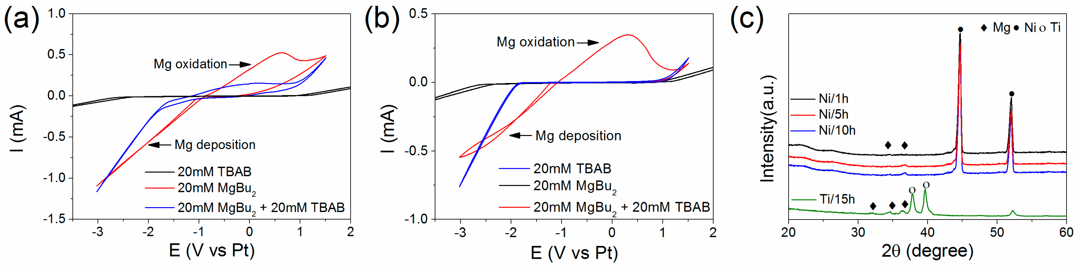
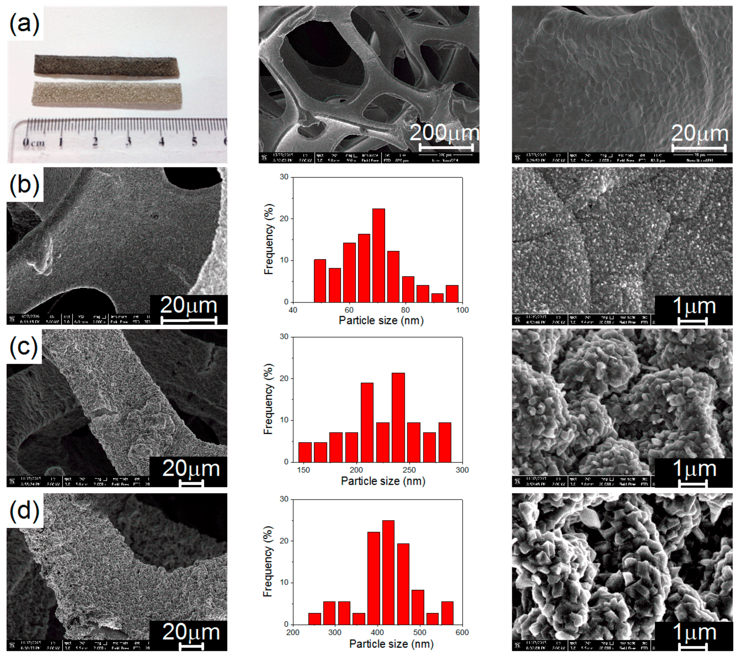
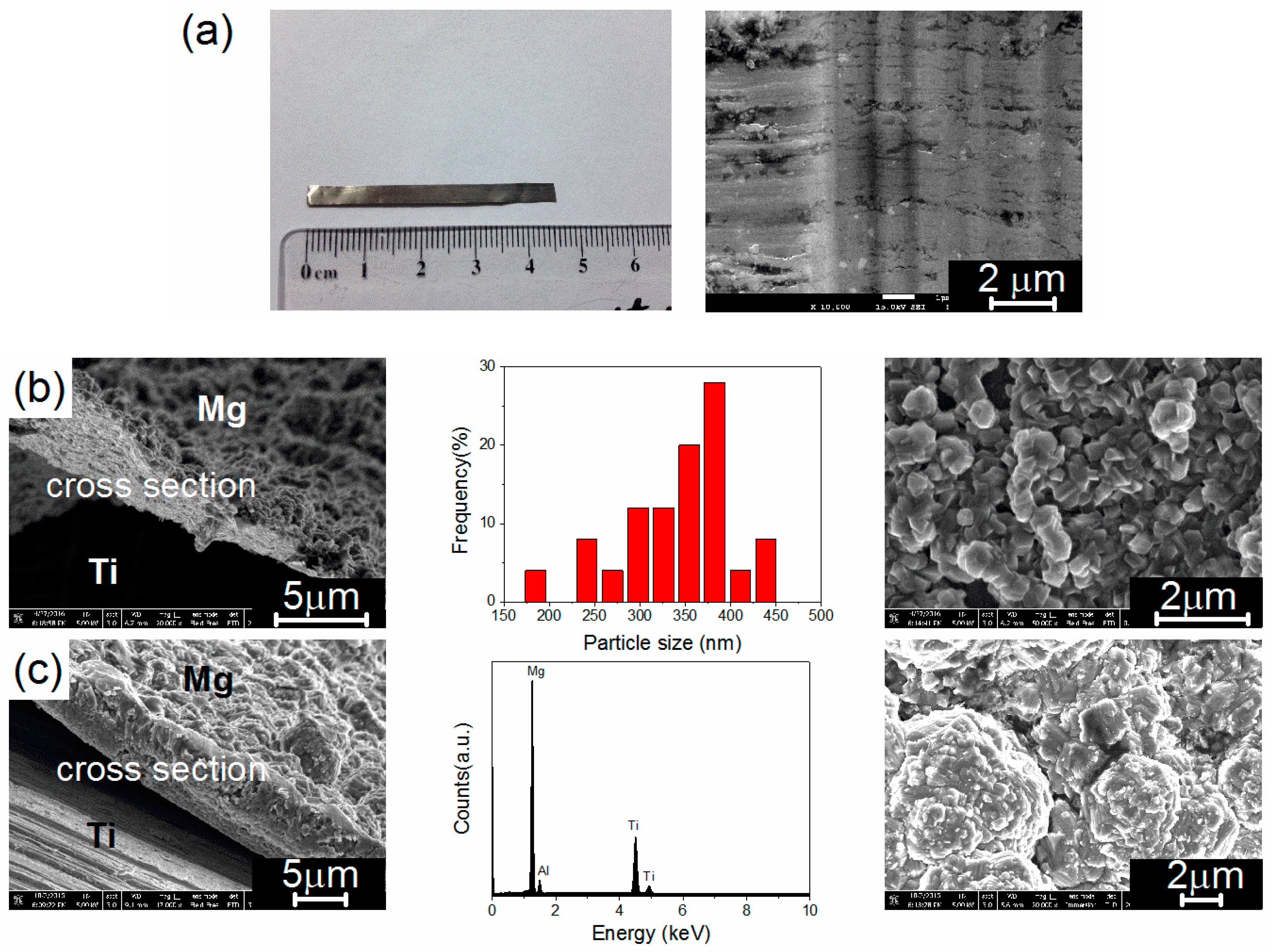
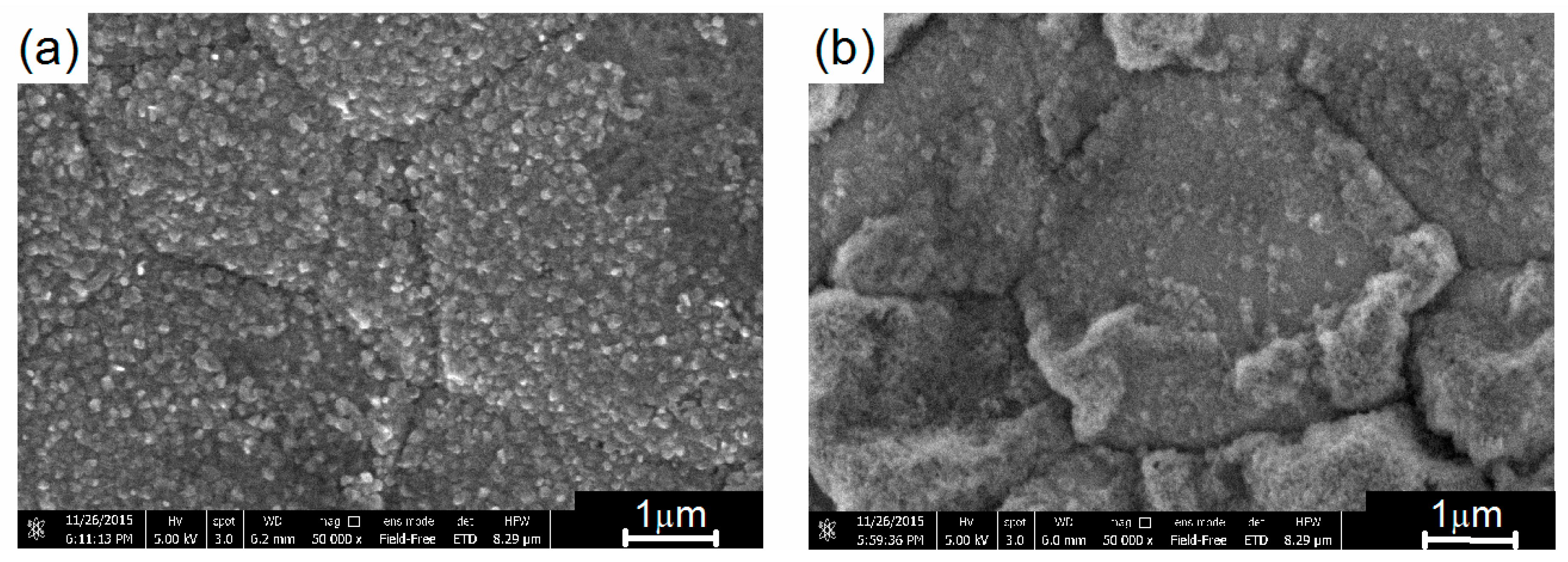
3.1. Electrochemical Deposition of Magnesium Nanoparticles and Structural Properties

Cyclic voltammograms were first acquired to confirm the deposition conditions for the different substrates. As shown Figure 1a,b, Mg was effectively deposited and reoxidised within a broad electrochemical window as per previous reports [27]. On both Ni and Ti, the addition of TBAB as a supporting electrolyte reduced the intensity of the reoxidation peak, indicating a better ability to form more strongly bonded Mg deposits [28]. It is noteworthy that the reduction current at the Ni foam was higher when compared to the Ti foil, and this was attributed to the higher surface area of the foam. Following the cyclic voltammogram, a current of −1 mA was used to ensure rapid nucleation and growth of the magnesium phase at the surface of the substrate.
After electrochemical deposition of magnesium, analysis by XRD confirmed that the electrodeposited material corresponded to hexagonal magnesium with very broad diffraction peaks only visible after a long deposition time (Figure 1c). The low intensity and broadness of these diffraction peaks suggested the formation of nanocrystalline magnesium particles.
Indeed, additional analysis of the Ni substrate by SEM confirmed the uniform deposition of small magnesium particles with an average size of 68 ± 11 nm after 1 h of deposition. Longer deposition times led to the growth of these nanoparticles up to an average size of 421 ± 70 nm after 10 h of deposition (Figure 2 and Table 1). Similar deposition time on the Ti substrate led to a more rapid deposition of magnesium. After 1 h, a relatively thick film of agglomerated magnesium particles with an average size of 341 ± 60 nm was already observed (Figure 3 and Table 1); and this suggested an easier deposition of magnesium on Ti and/or different nucleation and growth of the deposited magnesium phase. Indeed, longer deposition times led to the formation of “mushroom”-like structures of several microns (Figure 3c).

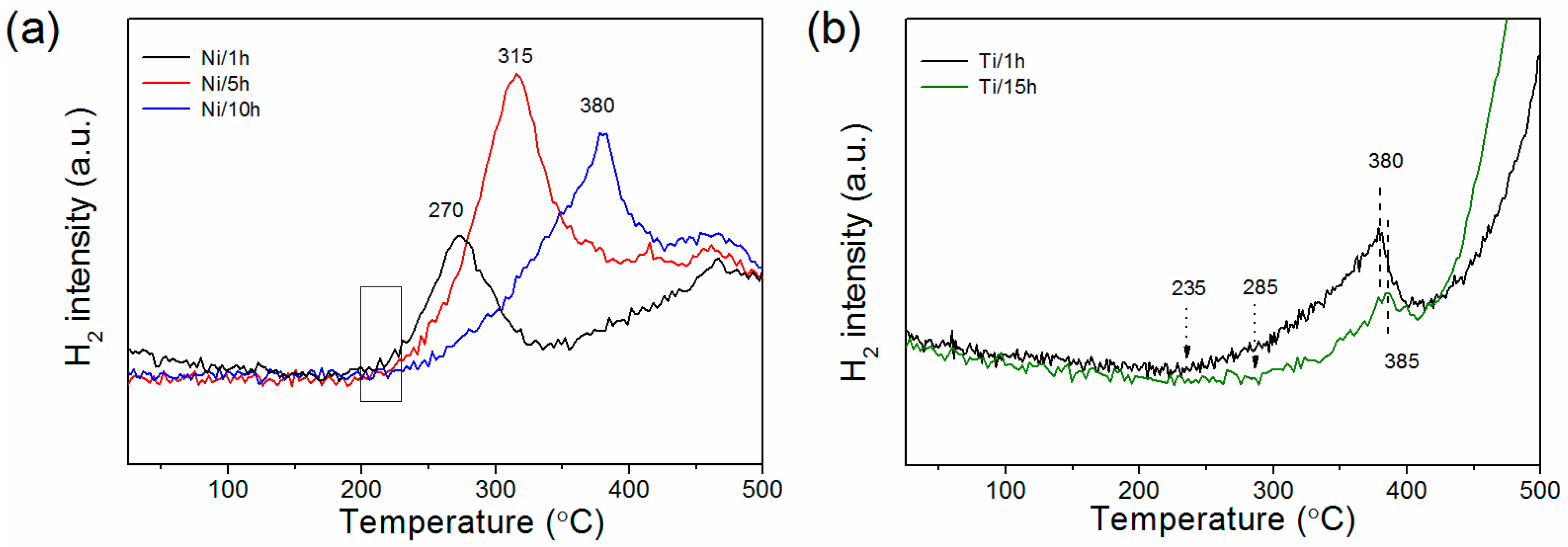
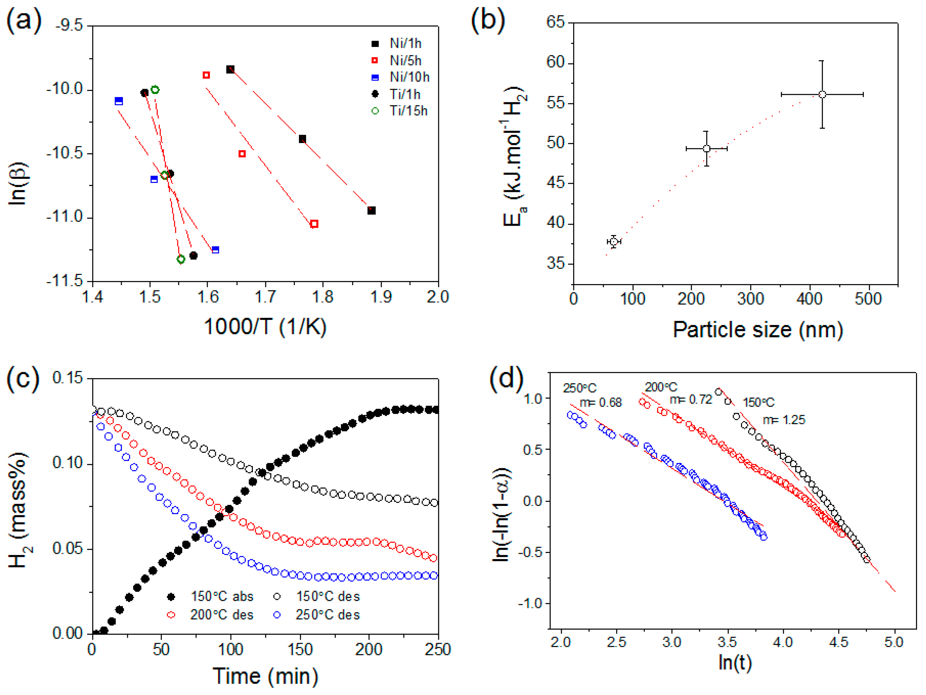
3.2. Hydrogen Sorption Properties

In order to assess the hydrogen sorption properties of the magnesium nanoparticles deposited at the Ni and Ti substrates, the materials were first hydrogenated at 200 °C under a hydrogen pressure of 3 MPa. At this temperature, the magnesium deposits were found to be stable (Figure 4a). However, at a higher temperature of 300 °C the film of the agglomerated magnesium nanoparticles started to degrade (Figure 4b). After hydrogenation at 200 °C, XRD analysis confirmed that the magnesium deposited on the Ti substrate for 15 h was fully hydrogenated (Figure S2), hence we assumed that full hydrogenation was also occurring for the smaller magnesium particles with very weak to no XRD diffraction peaks (i.e., Ni/1 h–10 h, Figure 1c).
The hydrogenated materials were then analysed by TGA/MS to determine their hydrogen desorption profiles. As shown Figure 5a, deposition of 1 h onto the Ni substrate led to the lowest hydrogen desorption temperature. The latter started at 210 °C with a peak at 295 °C. Higher deposition times led to an increase in the temperature at which hydrogen was released (Figure 5a), but remarkably the onset for hydrogen release remained at 210 °C. This may be regarded as the initial point to trigger hydrogen desorption and thus was assigned to the catalytic effect of the Ni substrate in facilitating the recombination of hydrogen atoms at the magnesium surface [29,30]. Indeed, on the noncatalytic Ti substrate, the onset temperatures for hydrogen desorption significantly differed (by 50 °C) as particle size increased and the surface area decreased accordingly (Figure 5b), in agreement with previous reports [15]. The initial desorption of hydrogen at 210 °C is also consistent with reported thermal desorption spectra of molecular hydrogen adsorbed at Ni surfaces [31,32,33]. It can thus be concluded that the shift in desorption temperature observed on the Ni catalytic substrate from 290 to 390 °C as particle size increased from 68 ± 11 to 421 ± 70 nm is related to rate-limiting steps other than hydrogen recombination at the magnesium surface.
In order to determine the evolution of the overall activation energy (Ea) of the hydrogen desorption process, hydrogen desorption profiles were measured by MS at different rates (Figure S4) and the Ea determined from the Kissinger’s equation (Figure 6a). The results are summarised in Table 1 and Figure 6b. Remarkably, Ea was found to be significantly lower on the catalytic Ni substrates than Ti. For example, the 341 ± 60 nm magnesium particles on the Ti substrate had an Ea of 125.4 ± 2.6 kJ·mol−1 H2, which is more than twice the activation energy of the 421 ± 70 nm magnesium particles at the Ni substrate. This is in agreement with previous reports showing a significant reduction of the activation energy when Ni is incorporated in the Mg/MgH2 system to minimise the first initial energy barrier of hydrogen dissociation/recombination at the magnesium surface. For example, Hanada et al. reported the significant decrease in Ea from 323 ± 40 to 94 ± 3 kJ·mol−1 H2 upon incorporation of nanosized Ni to ball-milled MgH2 [29]. It is noteworthy that for the smallest particle size of 68 ± 11 nm, Ea decreased to 37.8 ± 0.7 kJ·mol−1 H2 and, to the best of our knowledge, this is the lowest activation energy observed for the release of hydrogen from MgH2. Low activation energies have also been reported for other systems (e.g., on Cr-catalysed magnesium thin films a value of 65.7 kJ·mol−1 was reported [35]), while values ranging from 45.67 to 118 kJ·mol−1 have been reported for catalysed or uncatalysed ball-milled MgH2 [36,37,38,39]. Such a decrease in Ea could be assigned to reduced particle sizes in addition to the catalytic effect of Ni and/or additional contribution for varying crystallite sizes [40]. However, additional determination of the crystallite size by using the Scherrer equation reveals similar crystallite sizes for the magnesium particles deposited at the Ni and Ti substrates (Table 1). Hence, the decrease in Ea observed was assigned to the sole effect of particle size.
Similarly on the Ti substrate, Ea was found to decrease with particle size (Table 1). Like other systems including palladium [41], sodium alanate [42], and lithium amide [43]. It is thus apparent that Ea depends upon magnesium’s particle size, with the initial step of hydrogen dissociation/recombination as the main rate-limiting step. However, once this barrier is minimised though the use of a catalyst, additional rate-limiting steps will remain in the form of the hydrogen penetration, diffusion, and nucleation and growth of the hydride phase.
In order to determine the initial rate-limiting step of the hydrogen desorption process from the magnesium nanoparticles and assess the potential catalytic effect of the Ni substrate, the materials after 5 h deposition was cycled and the kinetics curves obtained were fitted using the general equation of a solid-state reaction (9) [44]:
G(α) = k × t
where α is the amount of hydrogen released in time t, k = k(T,P,r) is the reaction rate, and G(α) is a function depending on the mechanism controlling the reaction. The main theoretical functions G(α) are summarised in Table 2. In order to facilitate the fitting of the hydrogen curves measured and ease the distinction of reaction mechanisms, the method of Hancock and Sharp was used [45]. Since nucleation and growth processes in condensed systems follow the almost universal Equation (10), the method consists of plotting ln(−ln(1 − α)) versus ln(t).
α = 1 − exp(−Btm)
where B is a constant that depends on the nucleation frequency and linear rate of the grain growth, and m is a constant that varies according to the geometry of the system. Hence, determining the value of m would indicate the main rate-limiting step of the hydrogen desorption process.
Such an analysis was only possible for the material after 5 h electrochemical deposition, owing to the minimum amount of magnesium required to obtained meaningful kinetic curves and the need for relatively low hydrogen desorption temperatures to avoid any significant degradation of the magnesium film. Figure 6c,d show the hydrogen kinetics of the magnesium nanoparticles at different temperatures after initial hydrogen absorption at 150 °C, and the associated fits following the method of Hancock and Sharp [45] for α values comprised between 0.1 and 0.5 to minimise uncertainties related to the initial conditions of desorption, as well as any variations related to particle-size distribution and other geometrical effects. At the low temperature of 150 °C, the hydrogen desorption kinetics were slow and the slope of the fit was found to be close to m = 1.25 (Figure 6d), which indicates that the desorption process is surface-controlled. This is in agreement with the hydrogen desorption profiles observed at the Ni substrate (Figure 5a) and the significant hydrogen evolution happening for temperatures above 210 °C.
At higher temperatures, the hydrogen desorption kinetics were faster, and the slope of the fits shifted to values of m = 0.72 at 200 °C and m = 0.68 at 250 °C (Figure 6d). The rate-limiting step was thus assigned to a shrinking core model controlled by diffusion (i.e., the desorption is controlled by the reaction at the Mg/MgH2 shrinking core interface with the interface reaction proceeding at constant velocity and not the surface anymore). Hence, for the magnesium particle of 225 ± 35 nm, at low temperatures (<210 °C) the hydrogen desorption kinetics would be controlled by the ability of the surface to recombine hydrogen, while at higher temperatures (where this is facilitated by Ni), the main rate-limiting step would be the diffusion of hydrogen at the Mg/MgH2 interface. As particle size is reduced, such a rate-limiting step should be facilitated in agreement with the reduction in Ea observed (Table 1).
Previous investigations have shown that for bigger magnesium particles of a few micrometres prepared by ball-milling, the rate-limiting step is mainly controlled by the growth of several nuclei and thus the associated nucleation and growth process [1]. For much smaller magnesium particles of a few hundred nanometres it can be assumed that single nuclei will be formed and thus the reaction will then be controlled by diffusion, as currently found. Hence, improving the hydrogen kinetics will require finding effective additives to enhance the diffusion of hydrogen or synthesise novel magnesium nanocrystalline structures with enhanced hydrogen diffusion. At much smaller particle sizes of a few nanometres, the process has been reported to be controlled by nucleation and growth, owing the extremely short diffusion distances and the large surface area [20]. Hence, additional improvement will require an adequate catalyst to facilitate this process.

4. Conclusions

The electrochemical deposition of magnesium from the reduction of di-n-butylmagnesium on Ni and Ti substrates was used to generate magnesium nanoparticles of various sizes, and thus evaluate the evolution of Ea for the decomposition of MgH2 as a function of particle size. On the Ni substrate, magnesium particles with various sizes (ranging from 68 ± 11 nm to 421 ± 70 nm) were synthesised, and these particles showed a significant decrease in Ea as particle size decreased. Hence, Ea was reduced from 56.1 to 37.8 kJ·mol−1 H2 as magnesium particle size was reduced from 421 ± 70 to 68 ± 11 nm. Ea on the Ni substrate (56.1 kJ·mol−1 H2) was found to be much lower than on the Ti substrate (125.4 kJ·mol−1 H2) at similar particle sizes. More remarkably, Ea was found to depend upon particle size of magnesium with the initial step of hydrogen dissociation/recombination as the main rate-limiting step. However, once this barrier was minimised through Ni catalysis, the main rate-limiting step was found to be related to the hydrogen diffusion toward the desorbing MgH2/Mg interface. It is thus apparent that upon appropriate catalysis of the hydrogen dissociation/recombination, fast hydrogen kinetics should be feasible with very small magnesium particles. Assuming that similar improvements can be achieved with respect to the thermodynamic of the magnesium/hydrogen reaction, the approach of nanosizing may lead to an effective route toward room-temperature magnesium-based materials for hydrogen storage.

Supplementary Materials

The following are available online at www.mdpi.com/1996-1073/9/12/1073/s1, Figure S1: Amount of magnesium deposition at the surface of the Ni foam as function of time and corresponding charge passed through the electrochemical cell. The amount of magnesium was determined from ICP-OES analysis, Figure S2: XRD pattern of Ti/15 h after 200 °C hydrogenation, Figure S3: Hydrogen desorption profile of the Ni foam, Figure S4: Hydrogen desorption profiles obtained by MS at various heating rates (5, 10, and 20 °C·min−1) of the magnesium nanoparticle deposited at the Ni and Ti substrates. Only the first peak corresponding to hydrogen release from the magnesium nanoparticles supported on the Ni substrate was used to calculate Ea.

Acknowledgments

This research was supported by UNSW Internal Research Grant program. We appreciate the use of instruments at the Mark Wainwright Analytical Centre at UNSW. We are grateful to Simon Hager from the Mark Wainwright Analytical Centre at UNSW for the help with the SEM analysis.

Author Contributions

All the authors contributed equally to this work.

Conflicts of Interest

The authors declare no conflict of interest.

References

  1. Aguey-Zinsou, K.-F.; Ares-Fernández, J.-R. Hydrogen in magnesium: New perspectives toward functional stores. Energy Environ. Sci. 2010, 3, 526–543. [Google Scholar] [CrossRef]
  2. Sakintuna, B.; Lamari-Darkrim, F.; Hirscher, M. Metal hydride materials for solid hydrogen storage: A review. Int. J. Hydrogen Energy 2007, 32, 1121–1140. [Google Scholar] [CrossRef]
  3. Bobet, J.L.; Kandavel, M.; Ramaprabhu, S. Effects of ball-milling conditions and additives on the hydrogen sorption properties of Mg + 5 wt % Cr2O3 mixtures. J. Mater. Res. 2011, 21, 1747–1752. [Google Scholar] [CrossRef]
  4. Bobet, J. Study of Mg-M (M=Co, Ni and Fe) mixture elaborated by reactive mechanical alloying—Hydrogen sorption properties. Int. J. Hydrogen Energy 2000, 25, 987–996. [Google Scholar] [CrossRef]
  5. Song, M.; Kwon, S.; Hong, S.-H.; Park, H. Hydrogen storage properties of a Ni, Fe and Ti-added Mg-based alloy. Met. Mater. Int. 2012, 18, 279–286. [Google Scholar] [CrossRef]
  6. Liu, T.; Chen, C.; Wang, H.; Wu, Y. Enhanced hydrogen storage properties of Mg–Ti–V nanocomposite at moderate temperatures. J. Phys. Chem. C 2014, 118, 22419–22425. [Google Scholar] [CrossRef]
  7. Agueyzinsou, K.; Aresfernandez, J.; Klassen, T.; Bormann, R. Effect of Nb2O5 on MgH2 properties during mechanical milling. Int. J. Hydrogen Energy 2007, 32, 2400–2407. [Google Scholar] [CrossRef]
  8. Friedrichs, O.; Aguey-Zinsou, F.; Fernández, J.R.A.; Sánchez-López, J.C.; Justo, A.; Klassen, T.; Bormann, R.; Fernández, A. MgH2 with Nb2O5 as additive, for hydrogen storage: Chemical, structural and kinetic behavior with heating. Acta Mater. 2006, 54, 105–110. [Google Scholar] [CrossRef]
  9. Ares-Fernandez, J.R.; Aguey-Zinsou, K.F. Superior MgH2 kinetics with MgO addition: A tribological effect. Catalysts 2012, 2, 330–343. [Google Scholar] [CrossRef]
  10. Aguey-Zinsou, K.F.; Ares Fernandez, J.R.; Klassen, T.; Bormann, R. Using MgO to improve the (de)hydriding properties of magnesium. Mater. Res. Bull. 2006, 41, 1118–1126. [Google Scholar] [CrossRef]
  11. Pundt, A. Hydrogen in nano-sized metals. Adv. Eng. Mater. 2004, 6, 11–21. [Google Scholar] [CrossRef]
  12. De Jongh, P.E.; Wagemans, R.W.P.; Eggenhuisen, T.M.; Dauvillier, B.S.; Radstake, P.B.; Meeldijk, J.D.; Geus, J.W.; de Jong, K.P. The preparation of carbon-supported magnesium nanoparticles using melt infiltration. Chem. Mater. 2007, 19, 6052–6057. [Google Scholar] [CrossRef]
  13. Zlotea, C.; Oumellal, Y.; Hwang, S.J.; Ghimbeu, C.M.; de Jongh, P.E.; Latroche, M. Ultrasmall MgH2 nanoparticles embedded in an ordered microporous carbon exhibiting rapid hydrogen sorption kinetics. J. Phys. Chem. C 2015, 119, 18091–18098. [Google Scholar] [CrossRef]
  14. Zhao-Karger, Z.; Hu, J.; Roth, A.; Wang, D.; Kubel, C.; Lohstroh, W.; Fichtner, M. Altered thermodynamic and kinetic properties of MgH2 infiltrated in microporous scaffold. Chem. Commun. 2010, 46, 8353–8355. [Google Scholar] [CrossRef] [PubMed]
  15. Zlotea, C.; Latroche, M. Role of nanoconfinement on hydrogen sorption properties of metal nanoparticles hybrids. Colloids Surf. A Physicochem. Eng. Asp. 2013, 439, 117–130. [Google Scholar] [CrossRef]
  16. Smith, B.; Wepasnick, K.; Schrote, K.E.; Cho, H.H.; Ball, W.P.; Fairbrother, D.H. Influence of surface oxides on the colloidal stability of multi-walled carbon nanotubes: A structure-property relationship. Langmuir 2009, 25, 9767–9776. [Google Scholar] [CrossRef] [PubMed]
  17. Lai, Q.; Christian, M.; Aguey-Zinsou, K.-F. Nanoconfinement of borohydrides in CuS hollow nanospheres: A new strategy compared to carbon nanotubes. Int. J. Hydrogen Energy 2014, 39, 9339–9349. [Google Scholar] [CrossRef]
  18. Haas, I.; Gedanken, A. Synthesis of metallic magnesium nanoparticles by sonoelectrochemistry. Chem. Commun. 2008, 1795–1797. [Google Scholar] [CrossRef] [PubMed]
  19. Viyannalage, L.; Lee, V.; Dennis, R.V.; Kapoor, D.; Haines, C.D.; Banerjee, S. From Grignard’s reagents to well-defined Mg nanostructures: Distinctive electrochemical and solution reduction routes. Chem. Commun. 2012, 48, 5169–5171. [Google Scholar] [CrossRef] [PubMed]
  20. Aguey-Zinsou, K.-F.; Ares-Fernández, J.-R. Synthesis of colloidal magnesium: A near room temperature store for hydrogen. Chem. Mater. 2007, 20, 376–378. [Google Scholar] [CrossRef]
  21. Connor, J.H.; Reid, W.E.; Wood, G.B. Electrodeposition of metals from organic solutions v. electrodeposition of magnesium and magnesium alloys. J. Electrochem. Soc. 1957, 104, 38–41. [Google Scholar] [CrossRef]
  22. Gaddum, L.W.; French, H.E. The electrolysis of Grignard solution. J. Am. Chem. Soc. 1927, 49, 1295–1299. [Google Scholar] [CrossRef]
  23. French, H.E.; Drane, M. Electrolysis of Grignard solutions. J. Am. Chem. Soc. 1930, 52, 4904–4906. [Google Scholar] [CrossRef]
  24. Jolibois, P. On the formula of the organo-magnesian derivative and on the magnesium hydride. C. R. Hebd. Seances Acad. Sci. 1912, 155, 353–355. [Google Scholar]
  25. Aurbach, D.; Turgeman, R.; Chusid, O.; Gofer, Y. Spectroelectrochemical studies of magnesium deposition by in situ FTIR spectroscopy. Electrochem. Commun. 2001, 3, 252–261. [Google Scholar] [CrossRef]
  26. Setijadi, E.J.; Boyer, C.; Aguey-Zinsou, K.-F. MgH2 with different morphologies synthesized by thermal hydrogenolysis method for enhanced hydrogen sorption. Int. J. Hydrogen Energy 2013, 38, 5746–5757. [Google Scholar] [CrossRef]
  27. Aurbach, D.; Gizbar, H.; Schechter, A.; Chusid, O.; Gottlieb, H.E.; Gofer, Y.; Goldberg, I. Electrolyte solutions for rechargeable magnesium batteries based on organomagnesium chloroaluminate complexes. J. Electrochem. Soc. 2002, 149, A115–A121. [Google Scholar] [CrossRef]
  28. Oniciu, L.; Muresan, L. Some fundamental-aspects of leveling and brightening in metal electrodeposition. J. Appl. Electrochem. 1991, 21, 565–574. [Google Scholar] [CrossRef]
  29. Hanada, N.; Ichikawa, T.; Fujii, H. Catalytic effect of nanoparticle 3d-transition metals on hydrogen storage properties in magnesium hydride MgH2 prepared by mechanical milling. J. Phys. Chem. B 2005, 109, 7188–7194. [Google Scholar] [CrossRef] [PubMed]
  30. Liu, Y.; Zou, J.; Zeng, X.; Wu, X.; Li, D.; Ding, W. Hydrogen storage properties of a Mg–Ni nanocomposite coprecipitated from solution. J. Phys. Chem. C 2014, 118, 18401–18411. [Google Scholar] [CrossRef]
  31. Minachev, K.M.; Dmitriev, R.V.; Rustamov, M.I.; Kasimov, C.K.; Abad-zade, K. Thermal desorption of hydrogen from supported nickel catalysts. Bull. Acad. Sci. USSR Divis. Chem. Sci. 1981, 30, 1170–1176. [Google Scholar] [CrossRef]
  32. Christmann, K.; Schober, O.; Ertl, G.; Neumann, M. Adsorption of hydrogen on nickel single crystal surfaces. J. Phys. Chem. 1974, 60, 4528–4540. [Google Scholar] [CrossRef]
  33. Wright, S.; Skelly, J.F.; Hodgson, A. Energy disposal during desorption of D2 from the surface and subsurface region of Ni(111). Faraday Discuss. 2000, 117, 133–146. [Google Scholar] [CrossRef]
  34. Li, T.; Ma, G.H.; Sun, H.J. Ammonia-alkali solution coordination-precipitation route for preparation of beta-Ni(OH)2 nano-particles. Rare Met. Mater. Eng. 2014, 43, 563–566. [Google Scholar] [CrossRef]
  35. Fry, C.M.P.; Grant, D.M.; Walker, G.S. Catalysis and evolution on cycling of nano-structured magnesium multilayer thin films. Int. J. Hydrogen Energy 2014, 39, 1173–1184. [Google Scholar] [CrossRef]
  36. Shahi, R.R.; Tiwari, A.P.; Shaz, M.A.; Srivastava, O.N. Studies on de/rehydrogenation characteristics of nanocrystalline MgH2 co-catalyzed with Ti, Fe and Ni. Int. J. Hydrogen Energy 2013, 38, 2778–2784. [Google Scholar] [CrossRef]
  37. Li, P.; Wan, Q.; Li, Z.; Zhai, F.; Li, Y.; Cui, L.; Qu, X.; Volinsky, A.A. MgH2 dehydrogenation properties improved by MnFe2O4 nanoparticles. J. Power Sources 2013, 239, 201–206. [Google Scholar] [CrossRef]
  38. Juahir, N.; Mustafa, N.S.; Sinin, A.M.; Ismail, M. Improved hydrogen storage properties of MgH2 by addition of Co2NiO nanoparticles. RSC Adv. 2015, 5, 60983–60989. [Google Scholar] [CrossRef]
  39. Perejón, A.; Sánchez-Jiménez, P.E.; Criado, J.M.; Pérez-Maqueda, L.A. Magnesium hydride for energy storage applications: The kinetics of dehydrogenation under different working conditions. J. Alloys Compd. 2016, 681, 571–579. [Google Scholar] [CrossRef]
  40. Yao, X.; Zhu, Z.H.; Cheng, H.M.; Lu, G.Q. Hydrogen diffusion and effect of grain size on hydrogenation kinetics in magnesium hydrides. J. Mater. Res. 2008, 23, 336–340. [Google Scholar] [CrossRef]
  41. Langhammer, C.; Zhdanov, V.P.; Zorić, I.; Kasemo, B. Size-dependent kinetics of hydriding and dehydriding of Pd nanoparticles. Phys. Rev. Lett. 2010, 104, 135502. [Google Scholar] [CrossRef] [PubMed]
  42. Baldé, C.P.; Hereijgers, B.P.C.; Bitter, J.H.; de Jong, K.P. Sodium alanate nanoparticles—Linking size to hydrogen storage properties. J. Am. Chem. Soc. 2008, 130, 6761–6765. [Google Scholar] [CrossRef] [PubMed]
  43. Hoang, K.; Janotti, A.; van de Walle, C.G. The particle-size dependence of the activation energy for decomposition of lithium amide. Angew. Chem. Int. Ed. 2011, 50, 10170–10173. [Google Scholar] [CrossRef] [PubMed]
  44. Mintz, M.H.; Zeiri, Y. Hydriding kinetics of powders. J. Alloys Compd. 1995, 216, 159–175. [Google Scholar] [CrossRef]
  45. Hancock, J.D.; Sharp, J.H. Method of comparing solid-state kinetic data and its application to decomposition of kaolinite, brucite, and BaCO3. J. Am. Ceram. Soc. 1972, 55, 74–77. [Google Scholar] [CrossRef]
Figure 1. Cyclic voltammogram of di-n-butylmagnesium (MgBu2) with and without tetrabutylammonium bromide (TBAB) at (a) the Ni foam electrode and (b) the Ti foil electrode; and (c) associated X-ray diffraction (XRD) at different deposition times.
Energies 09 01073 g001
Figure 2. (a) Photo and typical SEM images of the pristine Ni foam; and typical SEM images and particle-size distribution of the magnesium nanoparticles obtained at different deposition times (b) 1 h; (c) 5 h; and (d) 10 h of di-n-butylmagnesium at the Ni surface.
Energies 09 01073 g002
Figure 3. (a) Photo and typical SEM images of the pristine Ti foil; and typical SEM images and particle size distribution of the magnesium nanoparticles obtained at different deposition times (b) 1 h and (c) 15 h of di-n-butylmagnesium at the Ti surface.
Energies 09 01073 g003
Figure 4. Typical SEM images of the film of magnesium nanoparticles obtained after 5 h of electrochemical deposition on Ni and subsequent hydrogenation at (a) 200 °C and (b) 300 °C and 3 MPa hydrogen pressure.
Energies 09 01073 g004
Figure 5. Hydrogen desorption profile of the magnesium nanoparticles deposited on (a) Ni and (b) Ti. Hydrogenation was carried out at 200 °C and 3 MPa hydrogen pressure. Additional hydrogen desorption >400 °C was assigned to the reduction of hydroxyls groups at the Ni surface (Figure S3). [34] The increase in signal above 400 °C on the Ti substrate corresponds to a drift of the baseline.
Energies 09 01073 g005
Figure 6. (a) Kissinger plot related to the hydrogen desorption from the magnesium nanoparticles deposited on Ni and Ti; (b) associated activation energy (Ea) as function of magnesium’s average particle size on the Ni substrates at 1, 5, and 10 h deposition time; (c) hydrogen kinetics for the material obtained after 5 h of electrochemical deposition; and (d) associated fit of the hydrogen kinetic desorption curves obtained at 150, 200, and 250 °C.
Energies 09 01073 g006
Table 1. Summary of the physical and hydrogen desorption properties of the magnesium nanoparticles deposited on Ni and Ti. Particle size was determined by SEM, crystallite size by the Scherrer equation, and activation energy (Ea) by using the Kissinger method.
SubstrateDeposition Time (h)Particle Size (nm)Crystallite Size (nm)H2 Desorption Temperature (°C)Ea (kJ·mol−1 H2)
Ni168 ± 11-29537.8 ± 0.7
5225 ± 3512 ± 233049.4 ± 2.1
10421 ± 7014 ± 239056.1 ± 4.2
Ti1341 ± 60-380125.4 ± 2.6
15-14 ± 2385240.1 ± 12.7
Table 2. Summary of main model functions describing solid–gas kinetics.
MechanismFunctional Time Dependence G (α)m
Surface control
S1α1.24
Random nucleation and growth (Avrami equations)
A1[−ln(1 − α)]1/44.00
A2[−ln(1 − α)]1/33.00
A3[−ln(1 − α)]2/52.50
A4[−ln(1 − α)]1/22.00
A5[−ln(1 − α)]2/31.50
Shrinking core with constant velocity: controlled by interface reaction
IP2—contracting surface1 − (1 − α)1/21.11
IP3—contracting volume1 − (1 − α)1/31.07
Shrinking core with decelerating velocity: controlled by diffusion
D1—1-D diffusionα20.62
D2—2-D diffusion(1 − α)ln(1 − α) + α0.57
D3—Jander, 3-D diffusion(1 − (1 − α)1/3)20.54

