Article

Development of a 60 kHz, 180 kW, Over 85% Efficiency Inductive Power Transfer System for a Tram

1
School of Electrical and Computer Engineering, University of Seoul, Seoul 02504, Korea
2
Metropolitan Transportation Research Center, Korea Railroad Research Institute, Uiwang 16105, Korea
*
Author to whom correspondence should be addressed.
Energies 2016, 9(12), 1075; https://doi.org/10.3390/en9121075
Submission received: 7 October 2016 / Revised: 3 December 2016 / Accepted: 8 December 2016 / Published: 16 December 2016
(This article belongs to the Special Issue Wireless Power Transfer 2016)

Abstract

:
Conventional contact-based train power transfer systems have high maintenance costs and safety issues and cause noise and additional aerodynamic drag. Instead of the conventional system, a loosely coupled online wireless power transfer (WPT) system for a train is proposed in this paper. The operating frequency of the proposed design is 60 kHz to ensure a low flux density and a high-efficiency system with a large air gap. In addition, a new transmitter track and pick-up geometry for 60 kHz operation are designed using finite element analysis (FEA). The proposed design is evaluated theoretically and experimentally. By using the simulated results, a new 180 kW, 15 m test-bed for a tram is constructed. The total power transfer efficiency is greater than 85% at the rated output power, and the loss distribution in the system is identified. Electromagnetic field (EMF) radiation and the voltage induction at the rail are measured for safety evaluation. The measured EMF satisfied international guidelines.

1. Introduction

Since the 1970s, most urban rail systems have been powered by overhead wires (or 3rd rails) and onboard pantographs. The overhead wire was a key enabling technology for electric trains. However, this conventional contact-based power supply system caused several issues: firstly, the mechanical wear of the overhead wires and pantographs required their periodical replacement, which results in high maintenance costs. Secondly, pantographs cause additional energy losses and noise problems because of their aerodynamic resistance (8% loss and they are the dominant noise source according to [1,2,3]). This is an important issue for high-speed trains because the aerodynamic losses are proportional to the square of the speed. Thirdly, the height of the overhead wire is an important limiting factor of the capacities of passenger and freight trains. In most of cargo ports, diesel-engine-powered trains that have a low efficiency and high air pollution are used because the height of the overhead wires is lower than the height of the freight containers and cranes. Lastly, overhead wires are dangerous to the general public because they carry high voltages (60 Hz, 25 kV) and currents without any sheaths. According to U.S. Federal Transit Administration, 48 people were killed or injured by touching overhead lines in 2000–2006 [4].
In this research, a loosely coupled wireless power transfer (WPT) system that is well-known to be suitable for a high-efficiency, high-power, large air-gap power transfer system is investigated as an alternative to conventional overhead wires for trains. A train powered by the WPT system has the following advantages: (1) no wear occurs, and regular maintenance is not required; (2) no energy loss or noise caused by the pantographs exists; (3) no capacity limitations caused by the overhead wires exist; and (4) no high voltage wire is exposed to the general public.
Many researchers have investigated WPT systems for trains [1,2,5,6,7,8,9,10,11]. Kawamura et al. [1] explored non-resonant and resonant WPT systems and proposed a new resonant WPT system with a 2 mm air-gap for trains in. However, the efficiency of the proposed WPT system was less than 70% at that small air gap, which is not suitable for MW level high-speed trains. Lee et al. proposed in 2012 transmitter and pick-up designs for a single-phase 20 kHz 100 kW WPT system for a train [7]. Their paper focused on reductions in the transmitter and pick-up sizes with a constant pick-up output voltage. However, the authors did not focus on the efficiency and electromagnetic-field safety (EMF safety), although those factors are the key metrics for the evaluation of high-power large air-gap WPT systems. Furthermore, the proposed system was not evaluated experimentally. In summary, the WPT research for trains began in the 1980s, but an efficient high-power large air-gap system that could potentially replace the conventional overhead wire system has not been developed yet.
In this paper, a new design for a single-phase 60 kHz, 180 kW online WPT system with a 7 cm air-gap for a tram is proposed and evaluated experimentally. In contrast to the previous studies, the operating frequency of the WPT system is increased to 60 kHz, which is three times higher than the the 20 kHz system reported in [12] to achieve a high-efficiency high-power WPT system with a compact size transmitter and pick-up. Furthermore, the Ohmic losses caused by the high operating frequency are considered in the system design to achieve a net efficiency greater than 85%. The designs of the 60 kHz transmitter track and pick-up are evaluated using a finite element analysis (FEA) and equivalent circuit analysis. Using the FEA and analytical results, a 15 m, 200 kW transmitter track and three 60 kW pick-ups are fabricated and mounted under the 180 kW tram. The proposed system is evaluated by comparison of the analytical, FEA, and experimental results.

2. Development of the 180 kW Level Inductive Power Transfer System

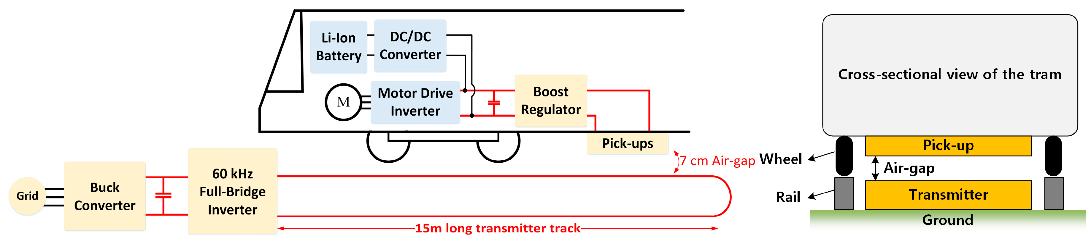
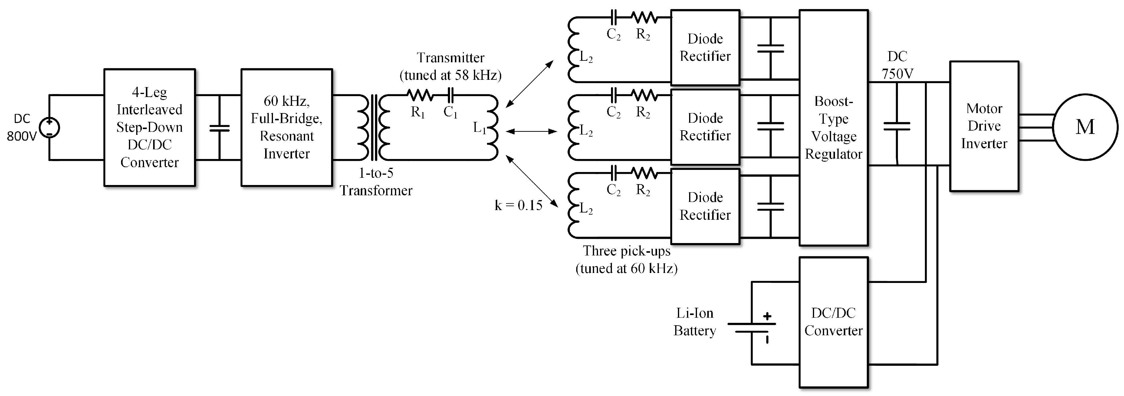
2.1. Configuration of the Target System

A block diagram of the WPT system for the tram is shown in Figure 1. A high frequency resonant inverter which is installed on the wayside delivers 60 kHz sinusoidal current to the series-tuned transmitter. Then, the transmitter coil which is installed on the ground plane generates a magnetic field that couples with the pick-up coil. The pick-up which is installed at the bottom of the tram transfers voltage and current to the voltage regulator. Finally, the voltage regulator supplies a constant voltage to the tram battery charger. The air gap between the transmitter and the pick-up is 7 cm. Because the air gap between the transmitter and the pick-up is very large, leakage inductances of the transmitter and the pick-up are very big compared to their mutual inductance. Series or parallel resonance tuning of the transmitter and pick-up coil are required to achieve a high-efficiency large-power system [13]. A series-series (SS) tuned resonant topology is used in this research because its resonant frequency is independent of the load variation and distance change [13]. Furthermore, the SS topology allows for easy manipulation of the voltage stresses of the capacitors and coils as it will be demonstrated in the following section.

2.2. High-Frequency Transmitter and Pick-Up Design

2.2.1. Design Considerations

In this study, design of the transmitter and pick-up was based on the 100 kW, 20 kHz WPT system for on-line electric vehicles (OLEVs) in [7,12]. Using the baseline design, the following factors in Table 1 have been considered in the design of the transmitter and pick-up coil geometries. In Korea, two frequencies are allowed for high power WPT systems, 20 kHz and 60 kHz. For this research, a 60 kHz operation has been selected unlike the 20 kHz systems found in the literature. As shown in Figure 2, the induced voltage at the pick-up is proportional to the frequency ( ω ), mutual inductance (M), and the current of the transmitter coil (I1). The transmitter current or the mutual inductance of a 60 kHz WPT system can be decreased to one third of those of a 20 kHz WPT system. Therefore, the 60 kHz operation is selected for high coil-to-coil efficiency, smaller transmitter and pick-up coil sizes, and low magnetic field radiation.

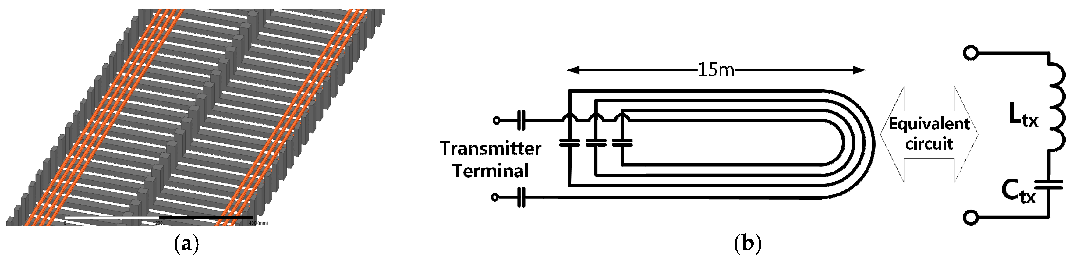
2.2.2. Transmitter Design

In the first step of the system design, a geometry of the transmitter coil has been determined. The number of turns and the width of the transmitter was determined considering the radiated magnetic flux density to the air. According to IEC 62110 and International Commission on Non-Ionizing Radiation Protection (ICNIRP) guideline [14,15], the radiated flux density should be smaller than 6.25 µT at three measurement positions placed horizontally 20 cm away from the outer surface of the tram and 50, 100 and 150 cm away from the ground. The tram was 2.6 m wide and the distance of outer surface of the tram from its center was 1.3 m. Therefore, the measurement positions are 1.5 m away from the center of the tram and 50, 100 and 150 cm away from the ground. Since the radiated flux density decreases as the distance increases, the flux density at the height of 50 cm is most intensive in all three positions. Therefore, the IEC standard can be satisfied if the flux density at the height of 50 cm is satisfied and this is the critical point in terms of the EMF safety.
Radiated magnetic flux density from the transmitter coil to the air can be calculated using Figure 3 and Equation (1):
B = i = 1 N [ μ 0 I 1 , r m s 2 π r i 1 μ 0 I 1 , r m s 2 π r i 2 ]
where, N is the number of turns of the coil, I1,rms is the rated current of the transmitter coil, ri1 and ri2 are the distance from a i-th turn of the transmitter coil to the observation point.
It should be noted that the magnetic flux density in the air is proportional to the product of the current and the number of turns (Ampere-turn), therefore, the radiated magnetic flux density at the measurement point is the same if the Ampere-turns are the same. As shown in [7,12,16], Amp-turn of the transmitter track for OLEV buses was 240 (240 Arms, 1-turn) to induce 500 Vrms at 20 kHz, 25 cm air-gap. In this research, Amp-turn of the new transmitter track was the same as the previous design, but the track width and the number of turns were changed. Using (1), the radiated magnetic flux density at the critical point of a 240 Amp-turn coil reached the 6.25 µT when the width of the coil is 48 cm. Therefore, the width of the track was 48 cm. Rated current of the track was determined regarding the availability of a 60 kHz operating Litz-wire. A 25 mm2 Litz-wire (60 µm/strand, 9000 strands, ampacity of 75 Arms) which was readily available in the laboratory was selected as a transmitter winding. Therefore, selected current rating of the transmitter was 60 Arms and the number of turns was four. In summary, the proposed transmitter was a four-turn, 15 m (L) × 0.48 m (W) coil with multiple E-shaped ferrite cores that were placed under the coil (see the 3D model of the transmitter in Figure 4a). The E-shaped cores of the transmitter were helpful in augmenting the flux linkage between the transmitter and the pick-up. Unlike the design in [16,17], the number of turns of the transmitter coil is increased to four and the rated current of the winding is decreased significantly which is helpful in improving the coil-to-coil efficiency. The self-inductance of the simulated transmitter winding was 576 µH and required capacitance for 60 kHz tuning was 12.2 nF.
It should be noted that the radiated magnetic flux density in (1) is not dependent on the operating frequency. That is, the magnetic flux density distributions of the 60 kHz and 20 kHz systems are the same if the number of turns and the current of the coils are the same. However, the transmitter coil of a 60 kHz system has three times higher voltage than a 20 kHz system because of the bigger reactance (ωL). This high voltage of the coil increases as the length of the transmitter track increases and handling the high voltage stress was one of the big challenges in implementing the on-line WPT system. Because the coil inductance was 576 µH, the voltage applied at the end-terminal of the coil was 13 kVrms which overwhelms the insulation levels of commercial wires and capacitors. In this paper, a new transmitter coil winding method was proposed in order to reduce the voltage stress of the coil as shown in Figure 4b. Instead of connecting the tuning capacitors (12.2 nF) at the end-terminals of the coil, three 47 nF capacitor-banks (series-connected seven 0.33 µF, 150 kVAR film capacitors) were connected at the end-terminals of inner three-turns and two 110 nF capacitor-banks (series-connected three 0.33 µF, 150 kVAR film capacitors) were connected at the end of the last turn. As mentioned earlier, this SS topology was good at reducing the voltage stresses of the coils and capacitors by distributing the capacitors. Using this distributed capacitor method, voltages across every turn of the transmitter coil reduced to 3 kVrms without disturbing its magnetic field distribution at the track. Photos of the transmitter track and the capacitors will be shown in a subsequent section.

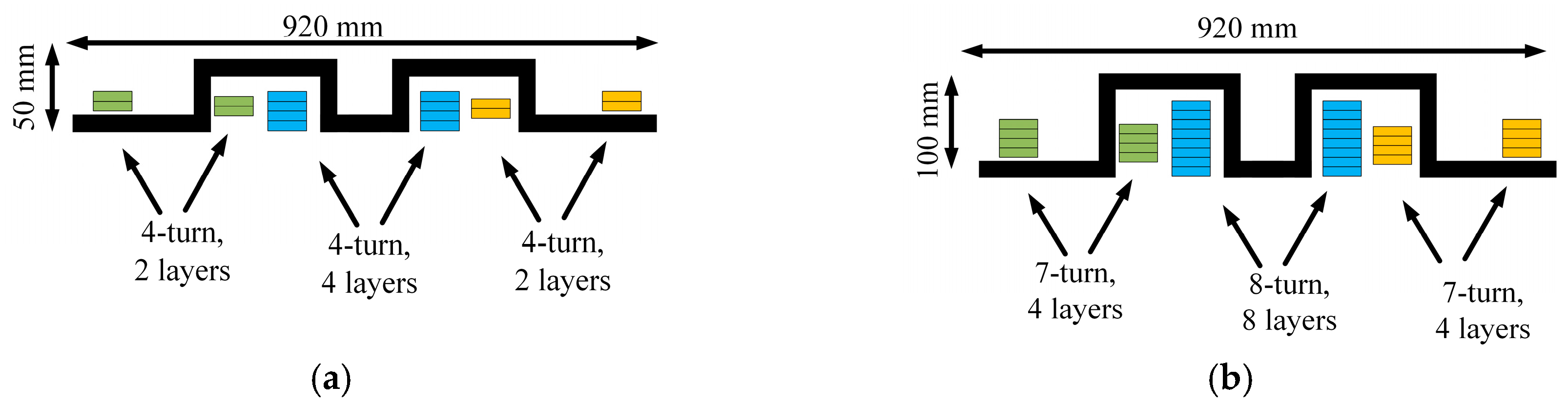
2.2.3. Pick-Up Design

In the following step, the geometry of the pick-up was determined. The key factor in designing the pick-up was the required induced voltage at the pick-up with the selected transmitter coil. A required mutual inductance value to obtain 750 VDC at the output of the pick-up has been calculated using Equation (2):
M = V o u t , D C 2 I 1 , r m s × ω × 4 π  
where, Vout,DC = 750 VDC is the rectified output voltage of pick-up, ω is the angular operating frequency, 2 and 4/π are scale factors for getting root mean square (rms) values from peak values. Using (2), the required mutual inductance for 750 VDC output was 30 µH. It should be noted that the required mutual inductance is 90 µH if the operating frequency is 20 kHz. That is, a 20 kHz system needs a pick-up that has larger number of turns and larger size core to achieve this three times larger mutual inductance.
The width, length and the number of channels of the pick-up were the same as the design in the literature (920 mm (W) by 600 mm (L), 4 channel) [7,12] in order to utilize readily available ferrite cores. In order to fully utilize the circulating magnetic flux, the one-winding layer at the center was connected in series with another one winding layer on the left or right wing side. This series-connection of two layers of the center and left or right side windings was called a “channel” and there were in total four channels in a pick-up and the four channels were connected in parallel so as to achieve the target output power (Figure 5a,b). In this research, the number of turns and corresponding height of the pick-up was changed using FEA simulations that result in the required mutual inductance. Using ANSYS MAXWELL, the mutual inductance has been calculated as the number of turns of the layers increase from 1-turn × 2 layers on the left wing, 1-turn × 4 layers on the center, 1-turn × 2 layers on the right wing. The mutual inductance reached 30.3 µH when the number of turns of the pick-up was 4-turns × 2 layers on the left wing, 4-turns × 4 layers on the center, 4-turns × 2 layers on the right wing. As demonstrated in [12], the number of turns of the OLEV was 28/64/28 turns which is equivalent to 7-turns × 4 layers on the right side, 8-turns × 8 layers on the center, 7-turns × 4 layers on the left side. However, the 60 kHz system has 8 (4-turns × 2 layers)/16 (4-turns × 4 layers)/8 (4-turns × 2 layers) turns. The final size of the selected pick-up design was 60 cm (L) × 92 cm (W) × 5.1 cm (H) for 60 kW output. Figure 6 compares the height and number of turns of the designed pick-up to 20 kHz pick-up in the literature. It should be noted that the number of turns and height of the new pick-up are much smaller than in the 20 kHz system design.
Tuning capacitors were connected in between the windings at center and side windings so as to reduce the voltage stresses at the windings. Net self-inductance of the pick-up at its output terminal was L2 = 71.3 µH and the required tuning capacitance was C2 = 98.7 nF. The geometric parameters of the transmitter and pick-up are summarized in Table 2. Also, simulated self- and mutual inductances of the designed system are summarized in Table 3. It should be noted that the mutual inductance was very small compared to the self-inductances of the transmitter and pick-up (coupling coefficient k = 0.15) that shows the loose coupling between the coils [13].
Control stability of the designed system has been checked using the calculated parameters of the system. According to [13,18], the control stability of a series-tuned WPT system is dependent on the coupling coefficient and impedance of the pick-up coil. If the system has unwanted multiple resonant frequencies or bifurcation phenomena, the power supply inverter cannot be operated at the tuned frequency which results in a degradation of the power transfer efficiency and power level. In order to avoid the bifurcation, the following condition needs to be met:
R L > k ω L 2  
where RL is the equivalent resistance of the load, k is the coupling coefficient, ω is the angular operating frequency, and L2 is the self-inductance of the pick-up. Since the equivalent load resistance RL decreases as the load power increases and the output voltage is constant, the load resistance at the rated operation should be considered for the stability check.
As the coupling coefficient of the designed system was 0.15 and ωL2 was 27 Ω, kωL2 was 4 Ω. The lowest resistance value of the designed system is 8.5 Ω when the load power is 60 kW at 750 VDC. Therefore, the designed system does not have any additional resonant frequencies. Rated output of the designed pick-up was 60 kW and three pick-ups were connected in parallel to achieve a 180 kW transfer as shown in Figure 7a.

2.2.4. Design Evaluation Using Finite Element Analysis (FEA)

Using FEA simulations (ANSYS MAXWELL, Release 17.2, ANSYS Inc., Canonsburg, PA, USA), it has been demonstrated that the coil-to-coil power transfer efficiency is greater than 95% at the tuned frequency and the radiated magnetic field at the observation point was less than 6 µT at for 60 kHz 180 kW transfer power. Simulated magnetic flux density distribution is shown in Figure 7c and the simulated efficiency dependences of the system on the load and operating frequency are shown in Figure 8b,c (red “×”).

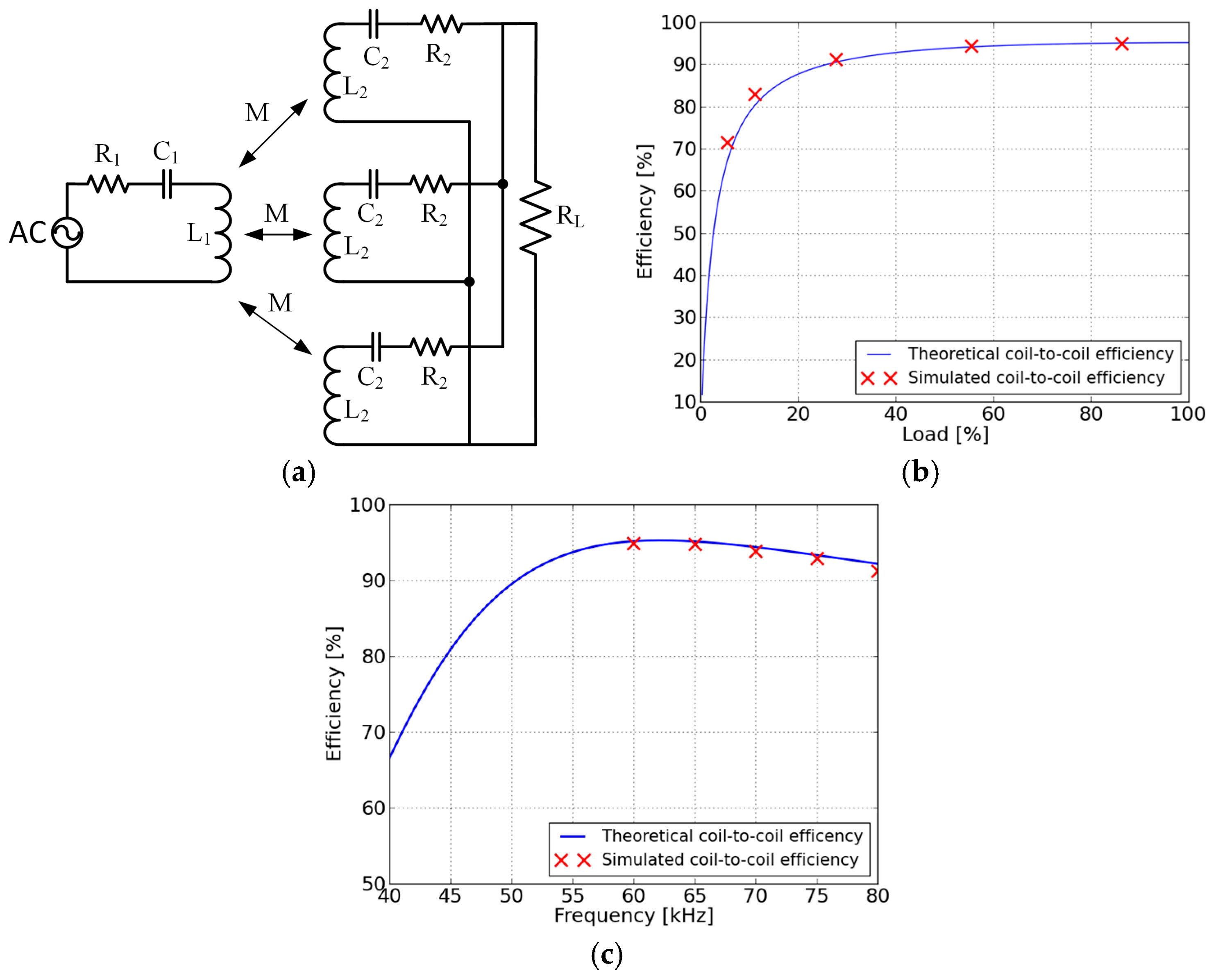
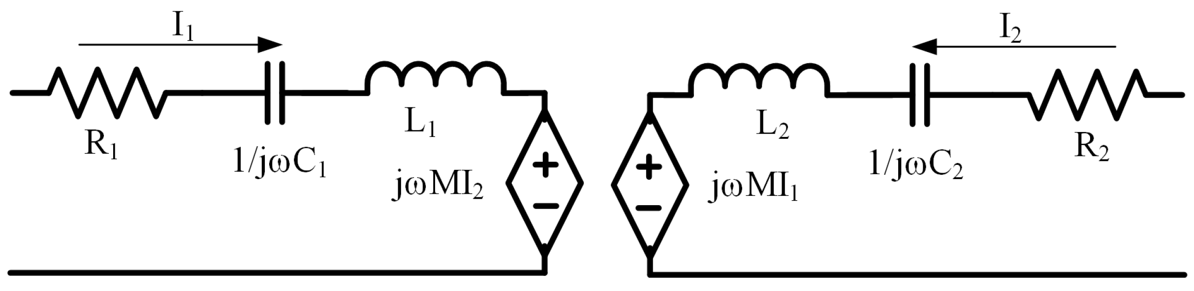
2.3. Theoretical Evaluation of the Designed System

Using Table 3, the power transfer efficiency, resonant voltage, and current waveform have been calculated with circuit simulation software. It should be noted that the lumped-parameter circuit model is valid if the wavelength of the electromagnetic field (EMF) is more than ten times larger than the characteristic lengths of the system [13]. The largest length of the designed system was the transmitter track length (15 m), and the wavelength was 5 km. Therefore, the proposed design can be analyzed with the lumped-parameter circuit modeling technique. According to [13], coil-to-coil efficiency of a SS system follows (4):
η s s = 1 1 + R 2 N R L + ( R L + R 2 ω M ) 2   R 1 R L    
where R1 and R2 are the series resistances of the transmitter and pick-up, respectively; N is the number of pick-ups; RL is the load resistance; M is the mutual inductance between the transmitter and the pick-up; ω is the angular frequency, respectively.
Figure 8a shows the equivalent circuit model of the SS WPT system. Figure 8b,c compares the calculated coil-to-coil efficiency using Equation (4) and the results of FEA depending on the load and operating frequency change. The x-axis of Figure 8b is the percent of the load compared to its rated output power. It should be noted that the theoretical coil-to-coil efficiency matches very well with the FEA results and the maximum coil-to-coil efficiency was over 95% at the rated operation. However, the efficiency degraded as the load reduces and the efficiency decreased to 71% when the load is 5% of its rated value. Mistuning of the operating frequency also affected the efficiency. The coil-to-coil efficiency decreased to 65% (or 91%) when the operating frequency is 40 kHz (or 80 kHz). The WPT system was not sensitive to the operating frequency if the operating frequency is over the tuned frequency, however, the efficiency decreased very fast as the operating frequency was lower than the tuned frequency.

3. Experimental Evaluation

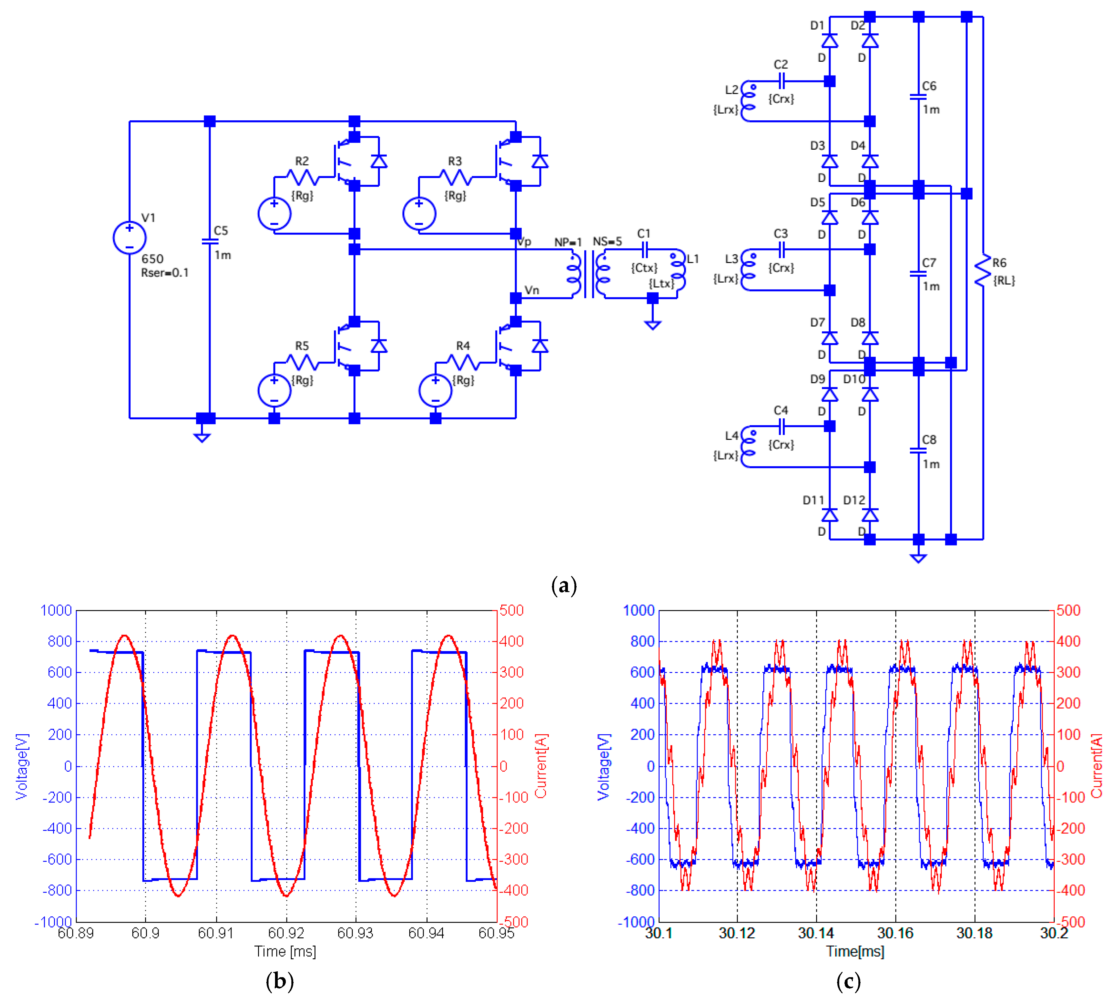
3.1. Experimental Setup

For the experimental evaluation, a tram which is powered by a constant 800 VDC voltage source from an overhead wire was changed to get power from the WPT systems. Figure 9 shows the overall configuration of the developed WPT system and photographs of the developed system are shown in Figure 10. The target tram equipped an 800 VDC, 110 ADC (88 kW) Li-ion battery pack, and the proposed 180 kW WPT system was used as a fast charger for the battery. A 200 kW full-bridge fixed-frequency resonant pulse amplitude modulation (PAM) inverter has been developed as the power supply.
The developed PAM inverter changed its peak output voltage depending on the output current level, but its duty ratio and operating frequency were fixed. In order to control the amplitude of DC link voltage of the inverter, a four-leg interleaved step-down converter was used. A constant 800 VDC voltage source for the overhead wire was used as the converter’s input power, and the converter controlled its output voltage for the PAM inverter. At the output terminal of the PAM inverter, a 1-to-5 transformer was used for impedance matching. The input impedance of the designed WPT system was 50 Ω at 60 kHz and the rated input voltage and current of the designed transmitter was 3000 Vrms, 60 Arms. Since the peak DC input voltage from the grid was 800 V, the transfer ratio was set to 1-to-5. Photographs of the PAM inverter and DC-DC converter are shown in Figure 10d,e. A series-tuned 0.48m (W) × 15 m (L) four-turn transmitter track was installed inside of a rail. As mentioned in the previous section, a 60 µm (strand diameter) 9000-strand Litz-wire was used for the transmitter winding. This 60 µm Litz-wire was very good against the skin-effect loss at 60 kHz because the diameter of the strands were very small compared to the skin-depth of the copper at that frequency (250 µm at 60 kHz). The E-shaped ferrite cores were made of a high-frequency high-permeability ferrite material, PL-13. Measured self-inductance of the transmitter coil was 557 µH and the measured capacitance was 13.7 nF as shown in Table 3. Photographs of the transmitter and capacitors are shown in Figure 10a–c.
At the bottom of the tram, three 60 kW pick-ups and a voltage regulator were installed and delivered power to the battery. The air-gap between the transmitter and the pick-up was 7 cm. The output terminals of the pick-ups were connected to diode rectifiers, and a boost regulator was used to supply a constant output voltage 800 VDC. An 80 µm, 2250-strand Litz-wire was used for the coil, and ferrite cores were used to build the M-shape pick-up core, as shown in Figure 5a. A 220 nF capacitor array (20 in series × 8 in parallel) was connected in series with the pick-up coil for tuning and its measured capacitance was 87.2 nF. Photographs of the one of pick-ups and capacitors are shown in Figure 10f,g. As shown in Figure 10h, three 60 kW pick-ups were connected in parallel to transfer 180 kW to the tram. Measured circuit parameters of the transmitter and pick-up are summarized in Table 3. It should be noted that the measured circuit parameters agreed very well with the simulated results. A boost regulator has been used to supply constant voltage to the tram. Unlike the wireless voltage control system in [17], the current controller of the wayside inverter and the voltage controller of the boost regulator operated independently. The twelve output channels of the three pick-ups were connected to the twelve legs of the boost regulator as shown in Figure 11. The regulator interleaved the twelve legs to mitigate the voltage and current ripple at the output. A photograph of the fabricated voltage regulator is shown in Figure 10i.

3.2. Experimental Results

3.2.1. Efficiency Measurement

The power transfer efficiency of the test-bed has been measured using a power analyzer. Dependencies of the power transfer efficiency on the operating frequency and load change were measured and are shown in Figure 12a,b. Measured total efficiency of the system was 85% at 60 kHz and 172 kW output whereas the simulated efficiency was 90%. The power transfer efficiency decreased to 78% when the load was 30% of the rated output. In addition, the efficiency decreased to 83% when the operating frequency was 65 kHz, while the test-bed was tuned at 60 kHz. The efficiency degradation due to the mistuning of the operating frequency was not very critical when the operating frequency is close to the tuned frequency. The discrepancy between the simulation and measured results originated from the DC-DC converter and output-voltage regulator, which were not included in the simulation.
Efficiencies of the individual components were shown in Figure 12c at the rated operation to evaluate the system performance. It should be noted that all the components exhibited over 95% and the resonant inverter had over 98% efficiency because of the zero voltage switching (ZVS) control. The voltage regulator had the lowest efficiency compared to other components. The coil-to-coil efficiency was 95%, as expected in Section 2.3. Although the individual efficiency of the power generator (including the input DC-DC converter, PAM inverter, and transformer) was greater than 97%, the total efficiency of the resonant inverter was 93%, which was lower than the coil-to-coil efficiency. Figure 12d shows the measured loss distribution in the system. The dominant losses originated from the input DC-DC converter, transformer, transmitter, and output-voltage regulator; therefore, the losses in these components should be reduced to achieve over 90% net efficiency.
A circuit simulation has been carried out with the parameters in Table 3 using LTspice to evaluate the measured results. The simulation model is shown in Figure 13a. The input DC-DC converter and output-voltage regulator were not included in the simulation model.
The output voltage and current of the full-bridge inverter were calculated using the model and compared to the measured results, as shown in Figure 13b,c. It should be noted that the output current lags the voltage because the operating frequency (60 kHz) was slightly higher than the tuned frequency of the transmitter (58 kHz) for the implementation of ZVS. Since the resonant inverter of this research was a PAM type, the ZVS operation is guaranteed in every load power if the system operates in ZVS mode at its rated output power. Therefore, the ZVS operation was checked at 172 kW transfer as shown in Figure 13. Simulated output voltage and current matched very well with the measured output voltage of the PAM inverter.

3.2.2. Electromagnetic-Field Safety

According to ICNIRP guidelines [15], the recommended maximum magnetic field density is 6.25 µT (rms) when the operating frequency is from 3 kHz to 150 kHz. In order to evaluate the EMF safety of the designed high-frequency high-power WPT system, the magnetic field near the WPT system has been measured following the measurement procedure guidelines in IEC 62110 [14] and plotted in Figure 14. Mean of the measured magnetic flux density at the three positions was 4.1 µT which is lower than the ICNIRP guidelines.

4. Conclusions

Overhead lines have been used for decades as power supplies for electric trains; however, overhead lines have high maintenance costs and safety issues, and cause noise and aerodynamic drag. Therefore, it is desirable to develop a new non-contact-based high-power high-efficiency power-supply system that is safe and economical. In this research, a new loosely coupled 180 kW online WPT system for a train with a 7 cm air gap and a total efficiency greater than 85% was proposed. The operating frequency of the WPT system was 60 kHz, which was three times higher than OLEV buses in order to improve the efficiency and power density. The transmitter and pick-ups were designed using a FEA simulation. The coil-to-coil efficiency, EMF safety has been considered in the design procedure. Simulated and calculated coil-to-coil efficiency was greater than 95%, and the EMF radiation level was lower than 6.25 µT. A new 180 kW, 15 m, 60 kHz WPT test-bed with a 7 cm air gap has been constructed and tested experimentally. A resonant inverter, DC-DC converter, and 1-to-5 transformer have been used as the pulse-amplitude-modulated power supply of the WPT system. A transmitter was buried under the ground, and resonant capacitors were connected in series with the transmitter coil. Three series-tuned pick-ups were installed under a test tram and connected in parallel. Measured resonant-inverter voltage and current matched very well with the circuit simulation results. Net power transfer efficiency at the rated output was greater than 85%. Efficiency dependencies on the load and operating frequency change were evaluated. Efficiencies of all components were measured and the loss distribution of the system was analyzed. Measured magnetic field radiation level satisfied international safety guidelines.

Acknowledgments

This research was supported by a grant (16RTRP-B097048-02) from Railroad Technology Development Program funded by Ministry of Land, Infrastructure and Transport (MOLIT) of Korean government and Korea Agency for Infrastructure Technology Advancement (KAIA).

Author Contributions

Jun-Ho Lee and Jae-Hee Kim conceived and designed the experiments; Seung-Hwan Lee performed the experiments; Seung-Hwan Lee and Jae-Hee Kim analyzed the data; Seung-Hwan Lee and Jun-Ho Lee wrote the paper.

Conflicts of Interest

The authors declare no conflict of interest.

References

  1. Kawamura, A.; Kuroda, G.; Zhu, C. Experimental results on contact-less power transmission system for the high-speed trains. In Proceedings of the IEEE Power Electronics Specialists Conference (PESC 2007), Orlando, FL, USA, 17–21 June 2007; pp. 2779–2784.
  2. Winter, J.; Mayer, S.; Kaimer, S. Inductive power supply for heavy rail vehicles. In Proceedings of the 2013 3rd International, Electric Drives Production Conference (EDPC), Nuremberg, Germany, 29–30 October 2013.
  3. Technologies–Aerodynamic Optimization of Pantographs. Available online: http://www.railway-energy.org/tfee/index.php?ID=220&TECHNOLOGYID=5&SEL=210 (accessed on 1 October 2016).
  4. Commuter Rail Safety Study. Available online: https://transit-safety.fta.dot.gov/publications/sso/CRSafetyStudy/html/CRSS.html (accessed on 1 October 2016).
  5. PRIMOVE True e-Mobility. Available online: http://primove.bombardier.com/application/light-rail/ (accessed on 1 October 2016).
  6. Hwang, K.; Kim, S.; Kim, S.; Chun, Y.; Ahn, S. Design of wireless power transfer system for railway application. Int. J. Railw. 2012, 5, 167–174. [Google Scholar] [CrossRef]
  7. Lee, S.; Jung, G.; Shin, S.; Kim, Y.; Song, B.; Shin, J.; Cho, D. The optimal design of high-powered power supply modules for wireless power transferred train. In Proceedings of the Electrical Systems for Aircraft, Railway and Ship Propulsion (ESARS), Bologna, Italy, 16–18 October 2012.
  8. Bolger, J. Roadway Power and Control System for Inductively Coupled Transportation System. EP Patent EP0289868A2, 9 November 1988. [Google Scholar]
  9. Tseng, L.; Tseng, D. Inductive Charging of a Moving Electric Vehicle’s Battery. U.S. Patent 5,311,973, 17 May 1994. [Google Scholar]
  10. Vietzke, O.; Czainski, R. Conductor Arrangement for Producing an Electromagnetic Field and Route for Vehicles, in Particular for Road Automobiles, Comprising the Conductor Arrangement. CA Patent App. CA 2839528A1, 17 January 2013. [Google Scholar]
  11. Woronowicz, K. System and Method for Transferring Electric Energy to a Vehicle Using Segments of a Conductor Arrangement Which Can Be Operated Independently. U.S. Patent US9331527B2, 3 May 2016. [Google Scholar]
  12. Shin, J.; Song, B.; Lee, S.; Shin, S.; Kim, Y.; Jung, G.; Jeon, S. Contactless power transfer systems for on-line electric vehicle (OLEV). In Proceedings of the 2012 IEEE International Electric Vehicle Conference (IEVC), Greenville, SC, USA, 4–8 March 2012.
  13. Lee, S.-H. Design Methodologies for Low Flux Density, High Efficiency, kW Level Wireless Power Transfer Systems with Large Air Gaps. Ph.D. Thesis, University of Wisconsin, Madison, WI, USA, 2013. [Google Scholar]
  14. International Electrotechnical Commission (IEC). Electric and Magnetic Field Levels Generated by AC Power Systems–Measurement Procedures with Regard to Public Exposure; IEC 62110; International Electrotechnical Commission: Geneva, Switzerland, 2009. [Google Scholar]
  15. International Commission on Non-Ionizing Radiation Protection (ICNIRP). Guidelines for Limiting Exposure to Time-Varying Electric, Magnetic, and Electromagnetic Fields (Up to 300 GHz). Health Phys. 1998, 74, 494–522. [Google Scholar]
  16. Shim, H.-W.; Kim, J.-W.; Cho, D.-H. An analysis on power variance of SMFIR structure. In Proceedings of the 2014 IEEE Wireless Power Transfer Conference (WPTC), Jeju City, Korea, 8–9 May 2014; pp. 189–192.
  17. Kim, J.H.; Lee, B.S.; Lee, J.H.; Lee, S.H.; Park, C.B.; Jung, S.M. Development of 1-MW inductive power transfer system for a high-speed train. IEEE Trans. Ind. Electron. 2015, 62, 6242–6250. [Google Scholar] [CrossRef]
  18. Wang, C.S.; Stielau, O.; Covic, G. Design considerations for a contactless electric vehicle battery charger. IEEE Trans. Ind. Electron. 2005, 52, 1308–1314. [Google Scholar] [CrossRef]
Figure 1. Overall configuration of the target tram system.
Energies 09 01075 g001
Figure 2. An equivalent circuit of a series-series tuned Wireless power transfer (WPT) system.
Energies 09 01075 g002
Figure 3. Reference geometry for the calculation of the radiated magnetic flux density.
Energies 09 01075 g003
Figure 4. Designed transmitter coil and its tuning method for voltage suppression: (a) a schematic of the designed 4-turn transmitter track; (b) distributed tuning method of the transmitter coil.
Energies 09 01075 g004
Figure 5. Designed receiver coil and its winding and tuning method for flux augmentation and voltage suppression: (a) a schematic of the designed receiver coil; (b) distributed tuning method of the receiver coil.
Energies 09 01075 g005
Figure 6. Comparison of the new and the previous pick-up design: (a) new pick-up design for 60 kHz operation; (b) previous pick-up design for 20 kHz operation.
Energies 09 01075 g006
Figure 7. Finite element analysis (FEA) model and simulated magnetic flux density distribution at its rated operation: (a) a top view of the designed WPT system; (b) a cross-sectional view; and (c) magnetic flux density distribution at 180 kW transfer.
Energies 09 01075 g007
Figure 8. Equivalent coil-to-coil model and its theoretical and FEA simulated coil-to-coil efficiencies: (a) equivalent circuit model; (b) efficiency vs. load; and (c) efficiency vs. operating frequency.
Energies 09 01075 g008
Figure 9. Equivalent block diagram of the developed test-bed.
Energies 09 01075 g009
Figure 10. Photographs of the developed test-bed: (a) transmitter; (b) transmitter tuning capacitor bank; (c) transmitter tuning capacitor; (d) the PAM inverter; (e) interleaved DC-DC converter; (f) pick-up winding; (g) pick-up tuning capacitors; (h) installed three pick-ups; (i) pick-up output voltage regulator; and (j) target tram.
Energies 09 01075 g010
Figure 11. Block diagram of the boost regulator and its connection.
Energies 09 01075 g011
Figure 12. Measured efficiency and loss of the test-bed: (a) total efficiency vs. load; (b) total efficiency vs. operating frequency; (c) measured efficiencies of the components; and (d) measured losses of the developed system.
Energies 09 01075 g012
Figure 13. Simulated and measured inverter output voltage and current waveforms: (a) Circuit simulation model; (b) Simulated results at 180 kW transfer; and (c) Measured results at 172 kW transfer.
Energies 09 01075 g013
Figure 14. Magnetic field radiation measurement positions and measured results: (a) measurement positions; (b) measured magnetic flux density.
Energies 09 01075 g014
Table 1. Wireless power transfer (WPT) system design requirements.
Design ParametersValuesDesign ParametersValues
Operating frequency60 kHzAir-gap7 cm
Track length15 mOutput power180 kW
Output voltage750 VDCCoil-to-coil efficiencyOver 95%
Magnetic field radiation6.25 μT--
Table 2. Summary of the designed transmitter and pick-up geometries.
Geometric parametersTransmitterPick-Up
Length (mm)15,000600
Width (mm)480920
Height (mm)5051
Number of turns per layer44
Number of layers18
Number of modules13
Table 3. Simulated and measured circuit parameters of the transmitter and the pick-up.
Circuit ParametersTransmitterPick-Up
SimulatedMeasuredSimulatedMeasured
Self-inductance (µH)57655771.379
Mutual-inductance (µH)30.333.3--
Tuning capacitor (nF)12.713.796.487.2
Equivalent series resistance (Ω)0.751.20.10.24
Tuned frequency (kHz)58.857.560.160.5

