1. Introduction
The use of wind as a renewable energy has rapidly developed in recent years [
1]. The global electricity production from wind sources is estimated at about 300,000 MW for 2015 compared to the 60,000 MW in 2005 [
2]. With the promulgation of the Renewable Energy Law in 2005 [
3], the electricity production from renewable energy in China has grown rapidly [
4]. Recently, it has been shown that wind power output is an intermittent energy resource [
5]. There is a growing effort for the development of wind energy [
6]. With the high penetration of wind power plants, the uncertainty and intermittency of wind power injected into the grid negatively influences the operation and security of modern power systems. The magnitude and direction of power flow of wind power plants are changed frequently with these factors. Which can cause the voltage instability and frequency fluctuations of the power systems. Due to these negative factors, the power quality and the stability of power systems can be declined and weakened respectively.
In order to enhance the power quality and stability of the power systems, many reactive power compensation devices are added to the grid at the point of common coupling (PCC) [
7]. Among these devices, the Static Var Compensation (SVC) is widely used to regulate voltage levels; it can improve the power factors, inhibit the voltage flicker and balance the asymmetric loads. However, the compensation devices cannot regulate the active power of the wind power plants [
8].
There are two categories to achieve the smooth control of the active power of wind power plants: direct power control and indirect power control. Direct power control is achieved by controlling the fan pitch angle or regulating the operating states of wind turbine generators without additional hardware devices [
9]. The direct power control cannot achieve the maximum power point tracking of wind power output [
10], and the utilization of the wind power is reduced with this approach. The latter method is achieved by configuring a certain capacity energy storage system (ESS) [
11], such as: batteries [
12,
13], flywheels [
14], superconducting coils and supercapacitors [
15]. The ESS can achieve a bidirectional active and reactive power exchange with power systems, realize the load shifting and smooth the injected power to grid.
The significant development of battery technologies has been applied in ESSs [
16]. For most of the batteries, the power density is quite low, although they have a relatively high energy density. The frequent charging-discharging may lead to a low lifetime in a battery energy storage system (BESS). The BESS is unable to regulate the second-level or minute-level fluctuations and disturbances in power systems. As the battery has a low power density, the use of battery energy system for smoothing the fluctuations of wind power output has a high cost. Considering lifetimes of the battery, the frequent charging and discharging of the battery should be avoided. Therefore, considering these factors, an advanced energy storage component to replace the battery in wind power regulation system is necessary.
The flywheels, superconducting coils and supercapacitors are better energy storage components used in current ESSs than batteries. These energy storage components have extensive application prospects. Nevertheless, the high manufacturing costs and limited storage capacities hinder their widespread applications in ESSs. Consequently, they are generally used in short-terms ESSs.
The types of ESSs become diversified with the increasing contribution of renewable energy sources integrated into the grid. We expect that the ESSs which are installed in the grid have a high power density and energy density. However, a single energy storage component is difficult to satisfy the two requirements simultaneously. Various hybrid energy storage systems (HESSs) are developed with multiple energy storage components in a few studies. In reference [
17], a HESS with superconducting magnet and secondary battery is developed with a high power density and energy density. In reference [
18], the authors proposed a basic structure with multi-level storage systems. Simulation and experimental results demonstrate the effectiveness of providing a prescribed amount of active power to the grid.
Synthetically considering the energy density, power density, implementation and operation-maintenance costs, it is suitable to build a HESS with battery and supercapacitor [
19]. The battery groups in the HESS can satisfy the requirements of slow power fluctuations. The supercapacitor groups have a fast response time (a few seconds) which is used to smooth the high-frequency fluctuations of wind power plants [
20]. With the full use of the two energy storage components, the lifetime of the batteries can effectively improve and the times of charge-discharge of the battery can be reduced, while the high power density of the supercapacitor is given full play [
21].
In this paper, we developed a HESS to smooth the wind power fluctuations. An allocation strategy was proposed to make full use of the advantages of the two energy storage elements in the HESS. Adjustment rules were designed considering the safety and efficiency of the energy storage elements. The experiments were conducted to demonstrate the validity of the proposed allocation strategy and designed adjustment rules. The experimental results under different scenarios indicated that the HESS can provide reactive support during voltage fluctuations, as well as improve power quality and enhance the stability of the power systems.
The paper is organized as follows.
Section 2 introduces the overall structure of the wind power regulation system. In
Section 3, the small-signal equivalent model is developed for designing the wind power regulation system. In
Section 4, the control strategies in DC/DC converter and DC/AC converter are developed. Experimental verifications are shown in
Section 5, followed by
Section 6 that concludes the paper.
2. The Structure of the Wind Power Regulation System
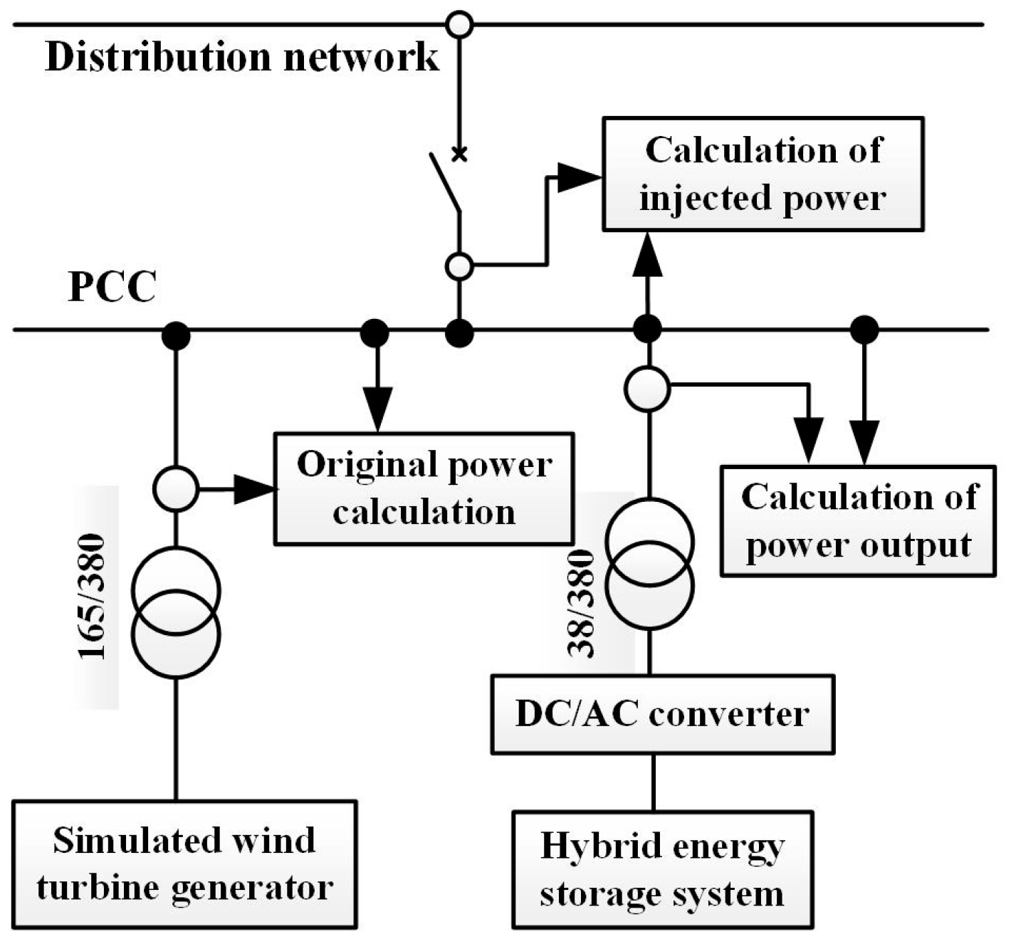
The overall structure of wind power regulation system is shown in
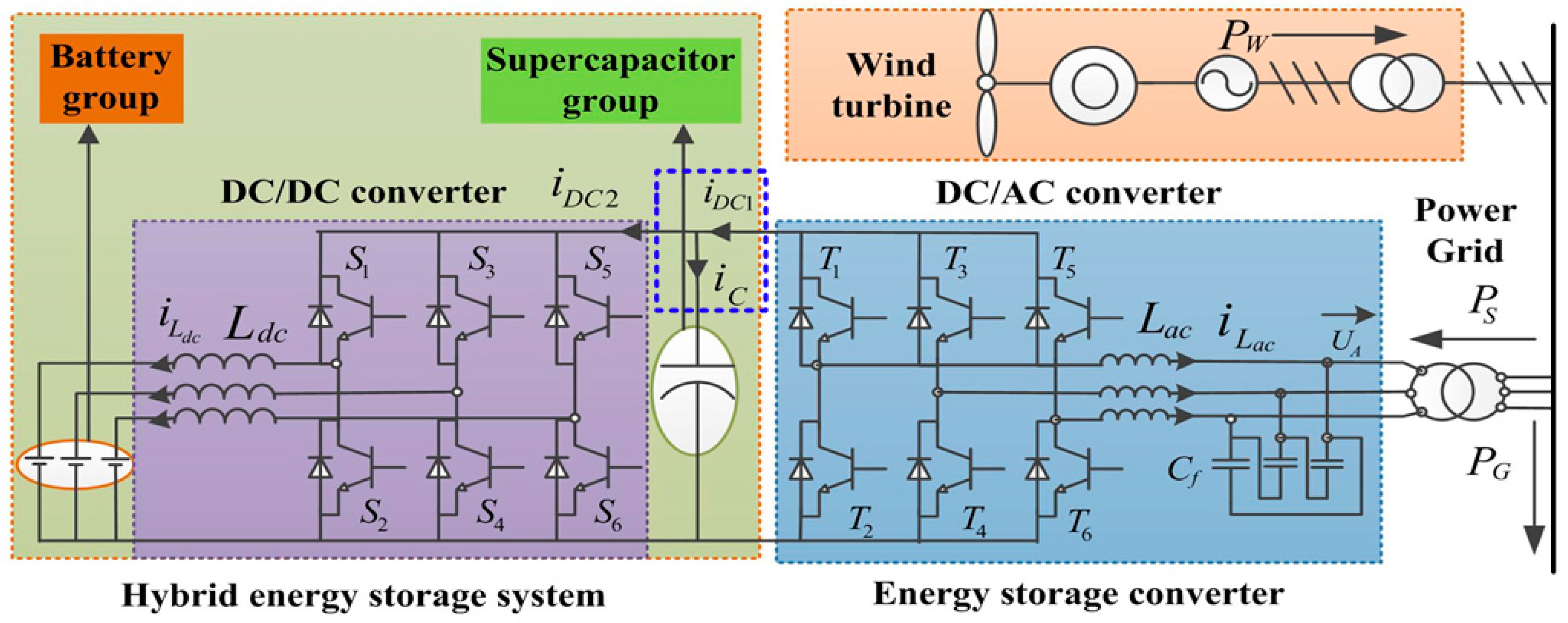
Figure 1. The wind power regulation system consists of a HESS and a DC/AC converter. The HESS is used to absorb the fluctuations of wind power output and to provide reactive power compensation. The DC/AC converter is used to achieve the bidirectional power exchange between the HESS and grid. The active and reactive power of the wind power plants is represented with
PW and
QW, respectively. The active and reactive power absorbed by HESS is represented with
PS and
QS. The relationship among three parameters of active power can be expressed as follows:
As seen from the blue box area in
Figure 1, the relationship between the battery current, supercapacitor current and the HESS current is:
where
iC is the HESS current,
iDC1 represents the battery current,
iDC2 represents the supercapacitor current.
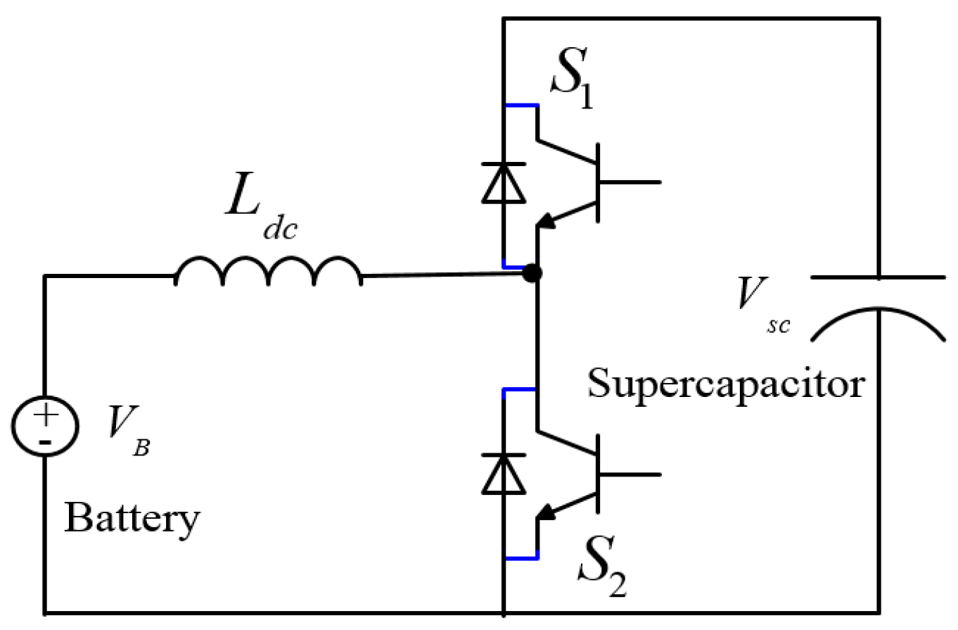
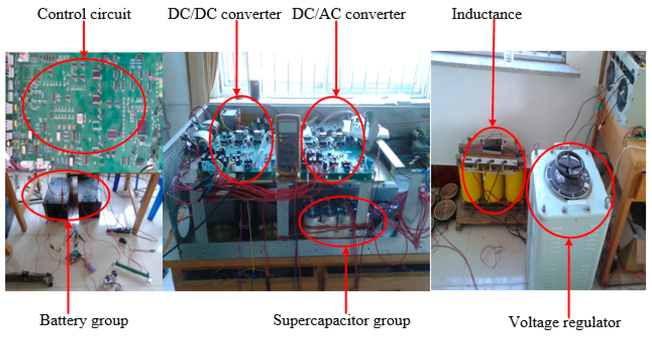
The hybrid energy storage system consists of a battery group, a supercapacitor group, a DC/DC converter. The battery and supercapacitor are connected in parallel with a triple DC/DC converter as shown in
Figure 2. The battery groups and supercapacitor groups are installed on the low-voltage side and high-voltage side of DC/DC converter, respectively. Because the main purpose of our study is to smooth the fluctuations of wind power output, the battery is regarded as a constant-current source, and the supercapacitor is regarded as a capacitance.
In this structure, there are many advantages, such as:
- (1)
The supercapacitor groups are used to buffer the power exchange between HESS and the grid, and the high power density of supercapacitor is given full play.
- (2)
The low-frequency components of wind power fluctuation are absorbed by battery groups, and thus the times of charge-discharge of the batteries can be effectively reduced.
- (3)
The three independent structures are connected in parallel with each other, and the pressure of average-current can be released as each one can be flexible controlled.
- (4)
It has a simple connective structure and a strong practicability.
In the wind power regulation system, the core execution unit is the energy storage converter. In this paper, we propose a power allocation strategy in the DC/DC converter to achieve power flow between the two energy storage components. The magnitude and direction of active power which is absorbed by HESS can be regulated by the DC/AC converter. Therefore, the injected power to the grid can be flexibly controlled. Moreover, the wind power flow control strategy and adjustment rules for regulating the SOC of the energy storage components are designed in DC/AC converter.
The output of the wind power fluctuates with the fluctuations of the wind energy sources i.e., atmospheric wind speed [
22]. Various studies show that the power systems are more sensitive to the power fluctuations in the medium frequency region (between 0.01 Hz and 1 Hz) [
23]. The bandwidth of the wind power fluctuations is generally located below that region [
11]. The power fluctuations with a high frequency (higher than 1 Hz) can be absorbed by wind turbines due to the mechanical inertia. It has little influence on the security and stability of power systems. Considering the security of the power systems, the power fluctuations (below 1 Hz) should be absorbed by additional devices.
3. Modelling of Wind Power Regulation System
The wind power regulation system consists of two parts: the HESS and DC/AC converter. In this paper, the outer voltage loop and inner current loop in the grid-connected converter are designed based on classical control theory and are suitable for a linear system. If the converter has nonlinear components, it is a nonlinear system. In order to design the control by using the classical control theory, it is necessary to linearize the converter on a quiescent operating point. The small-signal equivalent model is needed to analyze the dynamic performance and to calculate the parameters of the controller.
In this study, the state-space averaging method is used to establish the mathematic model of converters.
3.1. DC/DC Converter
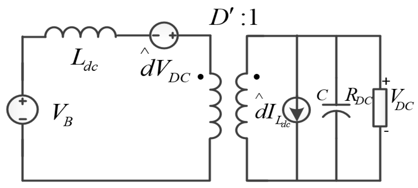
In this study, the DC/DC converter operates in Buck-Boost mode. In the DC/DC converter, each unit has a symmetrical relationship with other units in the structure. Therefore, the triple DC/DC converter circuit can be modeled by an independent unit. The purpose of the wind regulation system is used to smooth the fluctuations of wind power output. Therefore, the simple battery and supercapacitor models are used, which are constant-voltage source and capacitance.
Assume that the DC/DC converter is working at a quiescent operating point (
D,
UC,
IDC1,
ILdc,
RDC), where
D is steady-state duty ratio, and
,
RDC represents the equivalent load on the high-voltage side.
IDC is the inductance in DC side,
VDC represents the equivalent supercapacitor voltage on the high-voltage side, and
represents the disturbance quantity of duty ratio. Therefore, the small-signal equivalent model of DC/DC converter with a disturbance after linearization process is shown in
Figure 3.
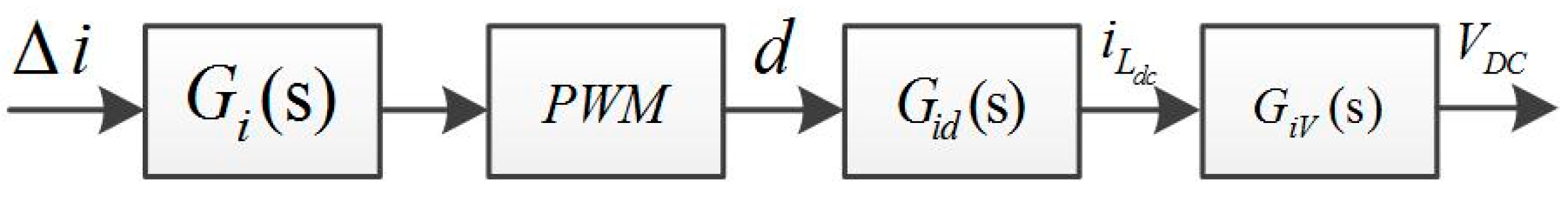
Based on the small-signal equivalent model, the flowchart of open-loop control structure with proportion-integral (PI) controller for current control is shown in
Figure 4.
In the above control structure, the involving transfer functions are presented as follows:
where
kiP and
kiI represent the coefficient of the PI controller,
C represents capacitance value of supercapacitor,
VDC represents the voltage of supercapacitor, and
Ldc represents the inductance value on the DC side.
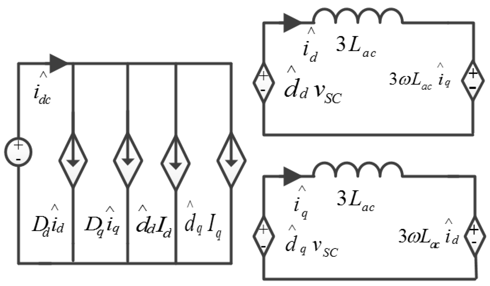
3.2. DC/AC Converter
In order to achieve flexible regulation of the DC/AC converter, the theory of instantaneous reactive power is used to decouple the active and reactive power [
24]. The small-signal linear equivalent model of DC/AC converter in
d-q space is presented in
Figure 5. In the model, we assume that there are no fluctuations in supercapacitor voltage and grid voltage considering different orders of magnitude of the time constant. As seen from
Figure 5, there is a symmetrical consistency in the control of active and reactive current; therefore, the same closed-loop PI adjustment is used to control the active and reactive current [
25].
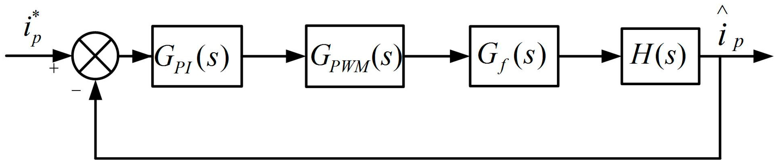
The control structure of active current is shown in
Figure 6.
Id and
Iq represent the active current and reactive current, respectively.
In the switching cycle, the feedforward method is proposed to decouple the active and reactive current without considering the fluctuations of DC-bus voltage. The transfer functions in
Figure 6 are expressed as follows:
where
kiP1 and
kiI1 represent the coefficient of PI controller in active current control,
Ks represents the gain coefficient of the thyristor,
represents the switching period of the thyristor,
Lac represents the inductance value in AC side,
R represents the resistance value in AC side,
and
are the disturbance quantity of the current after
d-q transformation,
and
are the duty ratio, and
Kf represents the decay coefficient in current sampling.
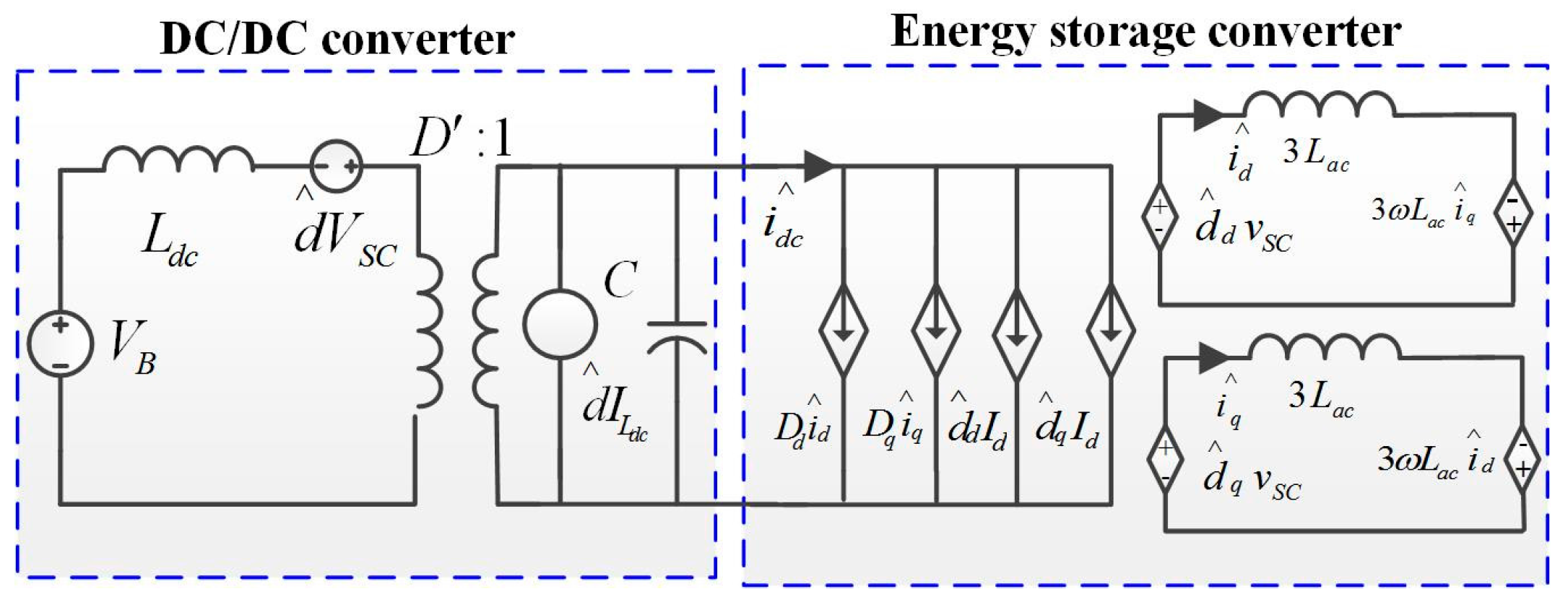
In conclusion, the small-signal equivalent models of converters are shown in
Figure 7. The models of the battery and supercapacitor used a constant-voltage source and a capacitance, respectively.
4. Control Strategy Design of the Wind Power Regulation System
In this section, the analysis and design of the allocation strategy to allocate the fluctuations of wind power output are presented. Considering the security of the two energy storage components, the real-time SOC should be considered in the process of tracking control. The decoupled control of the DC/AC converter was designed to achieve separate control of the active and reactive power.
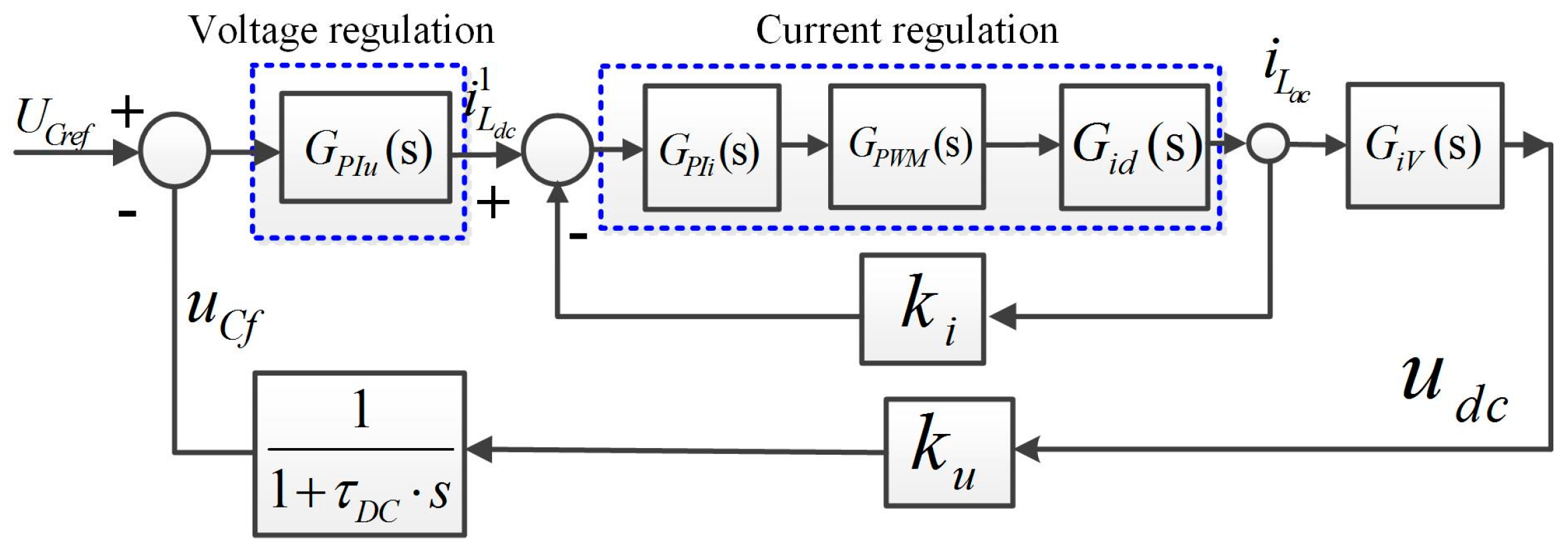
4.1. Allocation Strategy in DC/DC Converter
In the wind power regulation system, in order to give full play to the two energy storage components, the high-frequency and low-frequency components are absorbed by supercapacitor groups and battery groups, respectively. For achieving this target, the outer voltage loop and inner current loop are designed in the DC/DC converter as shown in
Figure 8. By inhibiting the low-frequency components of the supercapacitor voltage, the high-frequency components of the battery charge-discharge current can be effectively eliminated.
In our study, we ignore the power loss of the DC/AC converter. The target of the DC/DC converter is to maintain the supercapacitor voltage at a constant value. Therefore, the supercapacitor current can be effectively reduced. In the process of voltage tracking control in DC/DC converter, there is a small fluctuation in supercapacitor voltage. The current on the DC side fluctuates with the change of wind power plants. Meanwhile, the capacitance of the supercapacitor is relatively big. The supercapacitor voltage can be regarded as having no fluctuations.
Therefore, the power on the DC side is equal to the power on the AC side. The current on the DC side (
iDC1) fluctuates with the change of wind power plants. In order to obtain the frequency spectrum of the non-period current (
iDC1), Fourier transformation is used, and the frequency spectrum is expressed as follows:
where
IDC1L (
jω) is the low-frequency component of fluctuating wind power plants which is absorbed by battery groups, and
IDC1H (
jω) represents the other high-frequency components of fluctuating wind power plants.
Based on the relationship between voltage and current of the capacitor, while the current on the DC side is absorbed by the supercapacitor, the frequency spectrum of supercapacitor voltage can be expressed as follows:
where
uC is the voltage of the supercapacitor in a certain time period,
C is the capacitance value of the supercapacitor,
UCL (
jω) is the low-frequency components which respond to the current frequency spectrum, and
UCH (
jω) represents the other high-frequency components.
Equations (10) and (12) indicate that the voltage and current of the supercapacitor possess the same frequency fluctuation. Based on the above analysis, a current control mode consisting of an outer voltage loop and an inner current loop is designed to achieve the power allocation between the two energy storage components. The feedback of outer voltage loop is the supercapacitor voltage after a low-pass filter (LPF) as shown in (13).
where
uCf is the feedback of outer voltage loop,
ku is the voltage sampling coefficient,
τDC is the time constant of the filter related to the highest frequency which the battery groups can be absorbed.
In the inner current loop, the difference between the real-time supercapacitor voltage and reference voltage is regulated with a PI controller. The inductive current is the output of the PI controller.
where
iLref is the reference inductive current,
kuP is the proportional coefficient,
kuI represents the integral coefficient,
UCref is the reference voltage, the value is constant.
uCf is fluctuated with a low-frequency the same as
PS; therefore, the current of the battery groups fluctuates with the same frequency.
In the low-pass filter section, the amplitude-frequency and the cut-off frequency of the LPF are expressed as follows:
In this study, the highest frequency value which the battery groups can absorb is expressed
ωK. Assume that
ωc = ωK, therefore,
Based on these parameters, the amplitude is:
The amplitude attenuation of the LPF is relatively large. According to these parameters of the LPF, the high-frequency components of the current in battery groups can be effectively suppressed.
Synthesizing the above analysis, the overview control structure of DC/DC converter is summarized as shown in
Figure 7.
ki and
ku represents the feedback coefficient of the inner current loop and outer voltage loop, respectively.
4.2. State-of-Charge (SOC) Regions of Energy Storage Components
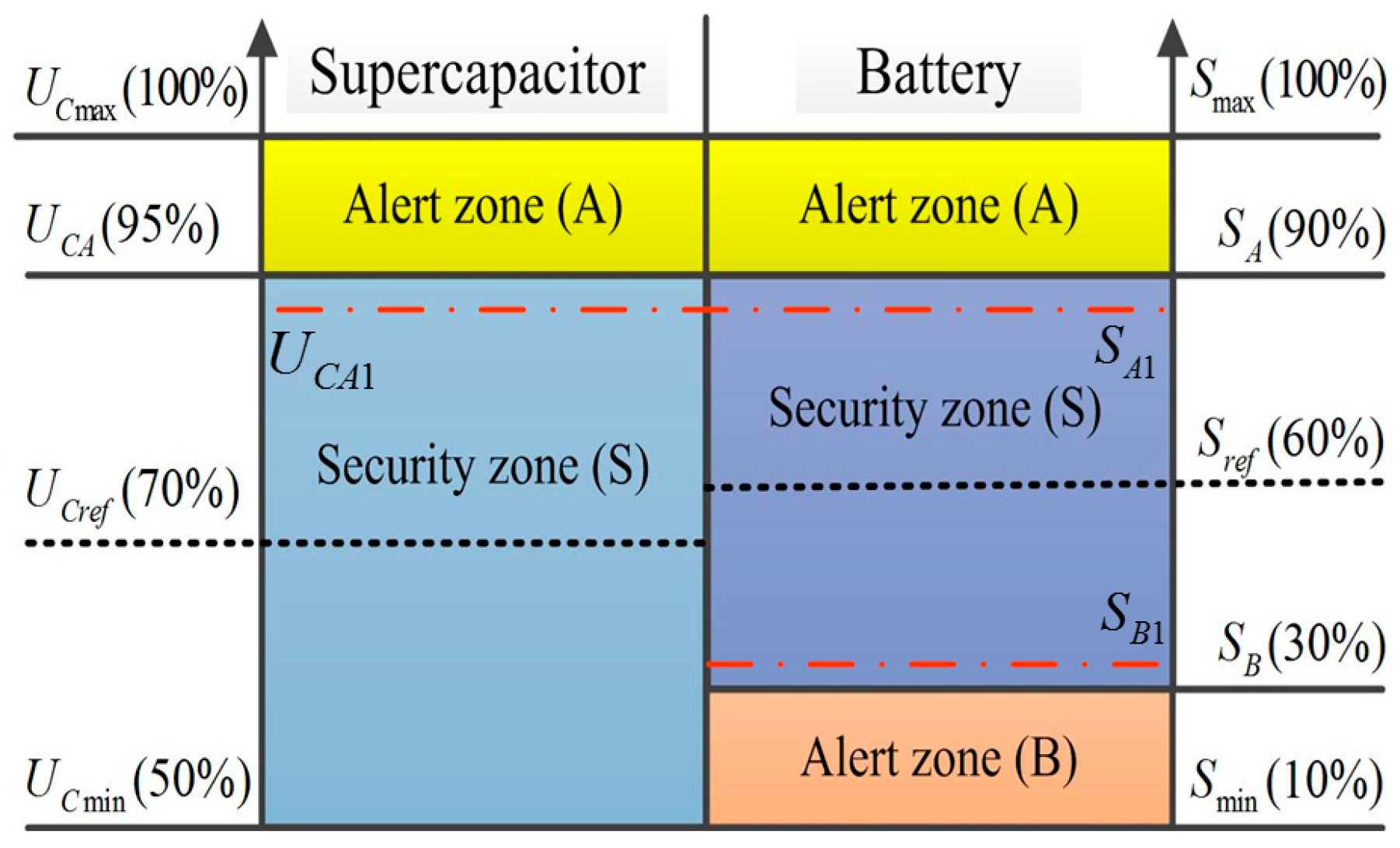
Considering the security of the energy storage components, the real-time SOC should be maintained within the security zone. For supercapacitor groups, the maximum operation voltage must be less than the rated operating voltage. The minimum operating voltage is equal to the battery voltage because the supercapacitor groups are located in the high-voltage side of the DC/DC converter. The SOC of supercapacitor is directly proportional to the square of voltage of the supercapacitor. Therefore, the range of operating voltage can be regarded as the permitted interval of SOC correspondingly. We expect that the real-time SOC of the supercapacitor is fluctuating at the middle level within the permitted interval. In this circumstance, the supercapacitor is fully used to achieve the bidirectional capacity in absorbing high-frequency components of the fluctuating wind power plants.
For battery groups, in order to avoid overcharge and deep discharge, we expect that the battery SOC fluctuates at the middle level of the permitted interval. In this circumstance, the bidirectional capacity of battery groups can be achieved to absorb the fluctuations of wind power plants. The SOC regions of the energy storage components are shown in
Figure 9.
As seen from the left side of
Figure 9, the SOC of supercapacitor is divided into two zones: alert zone (A) and security zone (S). When the SOC is in security zone (S), a close-loop controller is designed based on the low-frequency components of supercapacitor voltage. When the SOC is in alert zone (A), the close-loop controller is based on the instantaneous terminal voltage of supercapacitor considering the security of supercapacitor. In this circumstance, the time constant of LPF (
τDC) is set to zero. The hysteresis control strategy is proposed to avoid frequent switching of the DC/DC converter. When the supercapacitor voltage is lower than
UCA1, the adjustment rule to control the SOC of supercapacitor is activated.
The battery SOC is divided into three zones: alert zone (A), security zone (S), and alert zone (B). On the right side of
Figure 9, the permitted range of battery SOC is (
SA,
SB).
Sref is the expected level of battery SOC in the wind power regulation system. In alert zone (A), the current should be reduced to avoid overcharging of batteries. If the battery is working in the energy release state, there is no need to regulate the active current. If the battery is working in the energy storage state, the active current should be regulated in a negative correlation with SOC. The higher the SOC, the lower the active current magnitude. When the SOC is located at the peak value, the current is set to zero. In alert zone (B), the regulation method of active current is similar to the approach in alert zone (A).
4.3. Control Strategy in DC/AC Converter
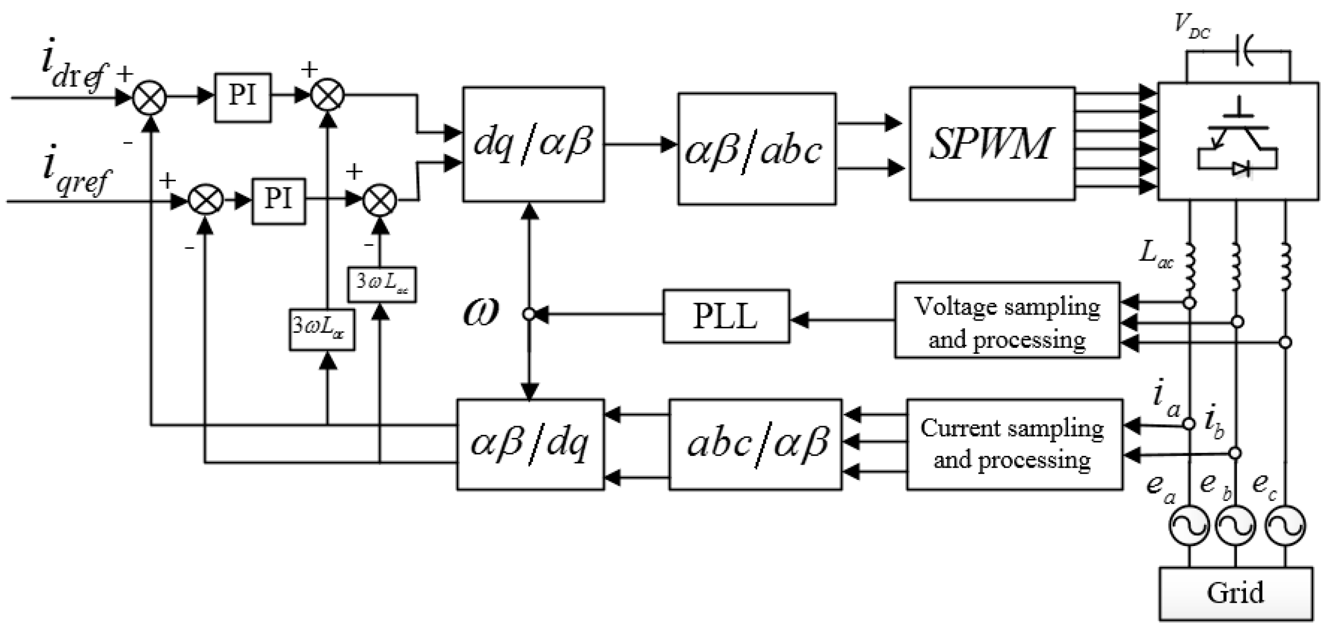
Based on real-time output of wind power plants and compensation targets of the power systems, the HESS system is used to absorb the fluctuations of wind power output and to provide reactive power support. The overview control structure is presented in
Figure 10.
Figure 10 shows the structure of current-vector tracking control in the
dq rotating frame. The reference values of active and reactive current come from the wind power upper-level regulation system. The corresponding feedback values are the real system currents transferred into the
dq rotating frame. The differences between reference and feedback values are regulated with PI controllers. In order to realize active and reactive power independent control, a feed-forward decoupling structure is incorporated into the control system. The reference voltages produced by the control system in the
dq rotating frame are then transferred into the
abc stationary frame and finally are modulated with sinusoidal pulse width modulation (SPWM) strategy to control the DC/AC converter.
In order to design the control system of the DC/AC converter, the instantaneous reactive power theory is used to translate the three-phase current into instantaneous active current and reactive current [
23]. The current command generation and tracking are the core control parts of DC/AC converter. In our study, based on the instantaneous reactive power theory, the three-phase current is translated into instantaneous active current and reactive current [
26]. The generations of the active and reactive current are shown in the following subsection.
4.3.1. Active Current Command
In order to minimize the negative impacts of wind power fluctuations to power systems, the injection active power from the wind farm or the low-frequency component of the original wind power output must remain constant. In both cases, the absorbed active power by HESS is expressed in (1). For the latter case, the injection active power can be expressed as in (18).
The actual active power which is absorbed by the DC/AC converter is:
where
is the time constant which is determined by the amplitude-frequency characteristic of LPF and the frequency suppression.
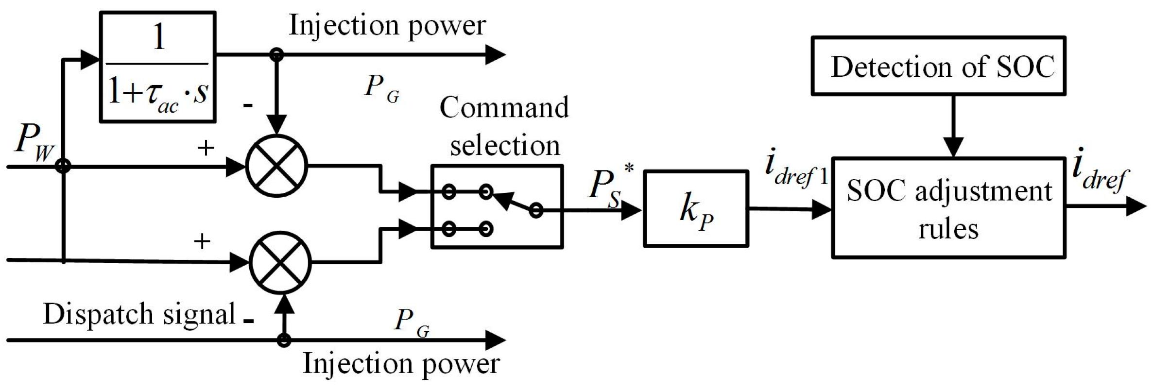
According to the target of the wind power regulation system, the active power which is absorbed by HESS is the reference command of the active current. The flowchart of the generation active current is shown in
Figure 11.
In the HESS, the battery groups are used to absorb the majority of the fluctuations of wind power plants. Considering the security and lifetime of batteries, adjustment rules for regulating battery SOC are proposed to avoid overcharge and deep discharge. The adjustment rules are shown in
Table 1. The batteries are working in the state of charging if the calculating current is larger than zero.
According to the battery SOC regions presented in
Figure 9, the adjustment coefficient can be expressed as follows:
where
K1 and
K2 are the adjustment coefficients of calculated current,
S represents the actual measurement of battery SOC,
Sref represents the reference battery SOC.
According to the adjustment rules in
Table 1, in security zone (S), the modified current is equal to the calculating current. In alert zone (A), if the calculating current is larger than zero, the modified current is changed to a new value based on (20). If the calculating current is less than zero, there is no need to regulate the calculating current. In alert zone (B), if the calculating current is greater than zero, there is no need to regulate the calculating current. If the calculating current is less than zero, the modified current is changed to a new value based on (21).
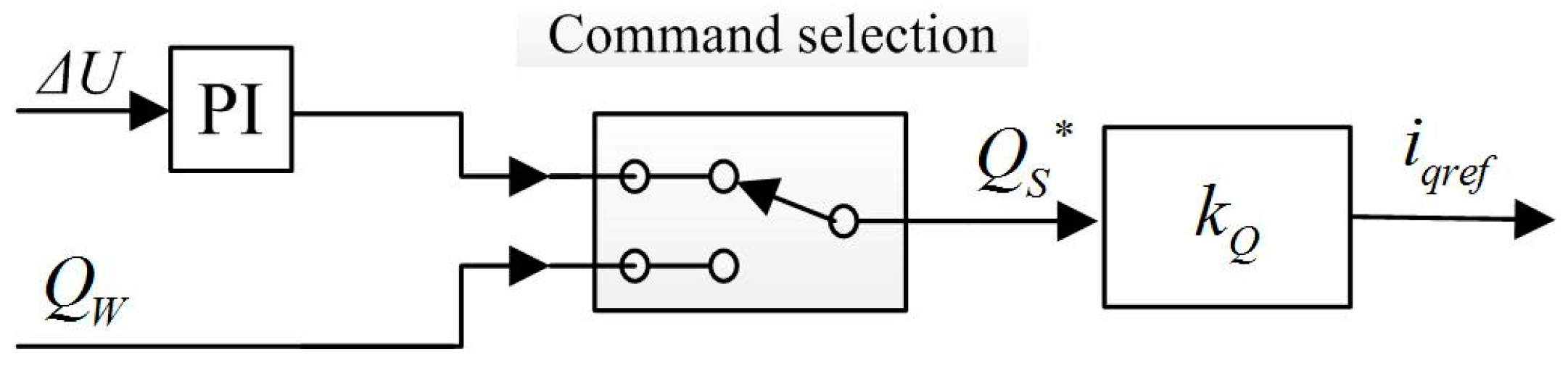
4.3.2. Reactive Current Command
The reactive power control mainly is reflected in the reactive power compensation to the grids. There are two ways to control the reactive power compensation: either the equivalent compensation follows the reactive output of the wind power plants, or it is based on voltage fluctuations at the access point of wind power plants to provide a certain amount of reactive power support. The reactive commands are generated in two ways, which are expressed as follows:
where
kQP and
kQI represent the proportional and integral coefficients, respectively.
ΔU represents the voltage deviation at the access point.
The generation of the reference reactive current is shown in
Figure 12.


