1. Introduction
The use of electric motors as the power sources of machines and equipment is increasing gradually in today’s industries, and most of them are induction motors (IMs). Compared to other types of electric motors, IMs are popular for their simple structure, low price, and high durability and reliability [
1,
2,
3].
The principle of the IM is that AC power is applied to the coil of the stator, which generates a rotating magnetic field that induces electromotive force and current in the rotor—by electromagnetic induction, and the rotor rotates. Research was initiated first by Ferraris and Tesla in the late 19th century, and until the mid-20th century there had been active research on the design and analysis of IMs. In addition, recent studies are focused on optimizing the design of IMs for high efficiency [
4,
5,
6,
7].
With the advance of IM technology, applications are being expanded, and depending on the required power of the application, three-phase IMs (TPIMs) are used for large power needs and single-phase IMs (SPIMs) are used to meet smaller requirements. Because SPIMs can use commercial power (110 V~220 V) as it is without additional power switching devices, they are used commonly for home appliances—particularly as the driving system of refrigerators and air-conditioners. These days, however, home appliances demand higher electric energy for their diverse functions and enlarged capacity, and this is raising a problem with regard to the performance of SPIMs as sources of mechanical power. In order to solve the performance problem, IMs have been replaced by the low-power and high-efficiency brushless direct current motors (BLDCMs). However, a BLDCM has a rotor with an interior permanent magnet and an additional controller is required in order to control the rotor. This characteristic increases the price of BLDCMs, and thus, relatively inexpensive SPIMs are still used more commonly [
8,
9,
10,
11].
Accordingly, research is being actively conducted for the purpose of finding ways of reducing the power losses of SPIMs, enhancing their efficiency. The efficiency of a SPIM can be improved by altering the fabrication method, materials, design technique,
etc. Regarding the former, we may improve the slot fill factor. It is the density of conductors (copper and aluminum) that are inserted into the stator slot. As for materials, we may increase the volume of electric conductors such as core, copper, and aluminum, or use magnetic steel sheets of low core loss. With design technique, we can optimize motor design for the target efficiency [
12,
13,
14].
Toward achieving a higher-efficiency SPIM, this study proposes a fabrication method that improves the fill factor of the rotor. In order to determine efficiency based on the aluminum fill factor of the rotor, we analyzed the distribution of magnetic flux density using the finite element method (FEM). Then, prototype rotors were made through conventional casting methods, which are pressure die-casting and centrifugal casting, and through the proposed method which is an improved type of centrifugal casting. And the fill factors of the prototype rotors were then measured. In addition, SPIMs to which these prototype rotors were applied were tested with a dynamometer, and their efficiencies were analyzed. Moreover, in order to examine the refrigerating capacity and performance of a refrigerator compressor with regard to the fill factor, a comparative experiment was performed with the three types of SPIMs applied to a compressor, using a calorimeter.
The reliability and validity of the proposed method were proven based on the results of the FEM analysis and the experiments.
2. The Characteristics of SPIM Rotor Casting Methods and Fill Factor
2.1. The Conventional Casting Methods
Figure 1 shows the pressure die-casting method, one of the conventional casting methods. The pressure die-casting method involves injecting aluminum at a high pressure into a metal mold, which is made precisely to coincide exactly with the form that is to be cast. The method produces a form identical to the metal mold, and horizontal and vertical structures are used for the die-casting machinery.
Because this method extrudes aluminum at a high speed and at high pressure into a mold, which uses a shock absorber, and the metal solidifies in the mold, the rigidity of the mold surface is high and molding is satisfactory. As the casting method is so simple, it is useful for mass production. Accordingly, most of the rotors are made through the pressure die-casting method.
However, because aluminum is injected into a metal mold at a high speed and high pressure, turbulent flow may happen during the extrusion. Moreover, contraction pores that happen as gas generated by the turbulent flow or air remaining in the metal mold is entrained cannot be entirely avoided. Therefore, the fill factor of SPIM rotors produced by the pressure die-casting method is about 85% [
15,
16].
Next, the centrifugal casting method shown in
Figure 2 uses the pressure of centrifugal force by injecting aluminum while rotating the metal mold at a high speed (hundreds~thousands of (rpm)). This method enables directional solidification through the centrifuging of metal oxides, and non-metallic inclusions,
etc. by their density differences. Thus, this method can make castings with superior properties.
On the other hand, it is a well-known fact that the speed of metal mold rotation has a decisive effect on the properties of the casting products of the centrifugal casting method. If the rotation speed is low, there may be burn-through or impurities are not removed sufficiently. If the rotation speed is high, circumferential stress induced by the centrifugal force becomes too high and causes cracks in the solidification layer. Therefore, it is very important to set the optimal mold rotation speed.
Because the centrifugal casting method forms the conductor part of a rotor using atmospheric pressure and centrifugal force generated by the rotation of the metal mold at 700~1000 (rpm), it can mold a casting with a relatively lower pressure than that which is necessary with the pressure die-casting method. A molded rotor in such a low-pressure condition can be formed with better insulation between the aluminum and the rotor lamination. In addition, because the contraction pores were reduced by improving aluminum fill factor of the rotor-slot bar and end-ring, it consequently is reduced rotor-bar resistance and porosity. After all, the centrifugal casting method can make a high-density rotor with high conductivity—therefore, a high-quality rotor.
However, because the molding happens at a low pressure, the rigidity of the mold surface is low and the inner part of the casting is highly likely to contain impurities due to the characteristics of the process. Moreover, compared to the pressure die-casting method the centrifugal casting method requires a large amount of initial investment in the equipment and its productivity is low. The fill factor of rotors produced by centrifugal casting is about 95%~99% depending on the process condition [
17,
18].
2.2. Proposed Casting Method (Improved Centrifugal Casting Method)
As explained in the previous section, the fill factors of rotors produced by the conventional centrifugal casting method are about 95%~99%, showing a large deviation. Thus, the inner part of the conductor may be eroded as it is solidified with a non-uniform filling of aluminum. This defect comes from the process of the centrifugal casting method. That is, because aluminum is injected with the mold rotating at a high speed, aluminum is pushed to the outer side of the rotor by rotational inertia. Consequently part of the inside is left empty in solidification.
In order to resolve this defect, this study proposes a method that raises the fill factor of the rotor up to over 99%. First, the mold rotation speed was adjusted from over 700 (rpm) to 600 (rpm) for the stable and uniform filling of the aluminum solution.
The rotational speed of the mold is derived from the relation between centrifugal force and gravitational force. That is, centrifugal force should be larger than gravitational force. The relational expression is as follows [
19]:
where
G: Gravity,
m: mass,
: acceleration due to gravity.
where
F: Centrifugal force,
m: mass,
r: radius,
ω: angular velocity.
where
D: Diameter.
Accordingly, the actual rotational speed is determined as a value larger than the minimum. Because it is selected experimentally, the rotational speed varies among researchers. In addition, the heating temperature (preheating) of the metal mold was raised from 200 °C to 250 °C in order to delay (prevent) the quick solidification of the aluminum solution because when the aluminum melt at 720 °C is injected into the rotor mold through the injection port of the centrifugal casting machine, heat is lost due to the contact of the high-temperature aluminum with the rotor core and this causes quick solidification.
3. FEM Analysis According to the Rotor Fill Factor of the SPIM
As explained in the previous section, the fill factors of rotors are distributed differently according to the casting method. Thus, we analyzed the magnetic flux density using FEM in order to assess the effect of the rotor fill factor on the efficiency of the SPIM.
In addition, the magnetic motive force of the SPIM can be explained with the rotating magnetic field theory as in
Figure 3, where, as shown, when the rotor rotates, magnetic motive forces take place clockwise (CW) and counterclockwise (CCW). In addition, each of the magnetic motive forces is 1/2 of the total magnetic motive force, and the phase at that time is wt. If the change of magnetic motive force distributes sinusoidally, the magnetic motive force can be expressed as Equation (6) [
20].
Equation (6) can be restated as Equation (7):
The parameters of the SPIM analysis model were as in
Table 1, and the properties of each rotor were analyzed, maintaining the same conditions except for the fill factor [
21,
22,
23].
The analysis used a single-phase two-pole IM, and analyzed only half of it.
Figure 4,
Figure 5 and
Figure 6 show the mesh plot of the IM model at 22°, the flow of the line of magnetic force, and the distribution of magnetic flux density according to the fill factor of the rotor. The number of mesh points was 13,136.
Figure 6 shows the magnetic field distribution according to the fill factor of rotor.
According to the results of FEM analysis, a high conductor fill factor of the rotor increased the current induced by the rotor and the magnetic flux caused by the current, and consequently decreased the stator magnetic flux density because of the reactance of the stator magnetic flux to the rotor magnetic flux.
From the results of FEM analysis based on this principle, when the fill factor was high it increased rotor magnetic flux density and decreased the stator magnetic flux density. That is, the improved fill factor of the rotor had a direct effect on the electric conductivity, and this is expected to improve the torque properties and efficiency of the motor.
4. Experiments and Results
This study is focused on raising the fill factor of rotors by improving the process of the rotor casting method. Thus, based on the results of the FEM analysis, three types of SPIM rotors were prepared, each with a different fill factor, and the experiment was conducted as follows.
The prototype rotors were made by the conventional pressure die-casting and centrifugal casting methods, and by the proposed centrifugal casting method, and they were compared through experiments. Firstly, the fill factor and filling state of the conductor part in the three types of rotors were examined, and secondly, the efficiencies of the SPIMs to which the three types of rotors were applied were compared using a dynamometer. Lastly, the SPIMs used in the second experiment were applied to a hermetic compressor, which was refrigeration and air-conditioning equipment for a refrigerator, and power consumption and refrigerating capacity were compared according to the measured fill factors, using a calorimeter.
4.1. Comparison of Rotor Filling State
For the comparative analysis of the filling state of the three types of rotors, prototype rotors were prepared for each type, as in
Figure 7, in the rotor core of the same size as in
Figure 8 (outer diameter Φ60 × lamination 48 mm).
In order to test the effects of pressure differences between the two processes, namely, the pressure die-casting method and centrifugal casting method, on the filling state, we prepared prototype rotors with other conditions remaining the same except for the properties of the casting metal mold—aluminum purity (99.7%) and melting furnace temperature (720 °C). For the proposed casting method too, prototype rotors were made using the same process conditions as the conventional centrifugal casting method except for the rotation speed and the heating temperature of the mold. The outward shape was somewhat different between the rotors made through the pressure die-casting method and the centrifugal casting method, but there was no difference between those made through conventional centrifugal casting and the ones cast with the proposed method.
Table 2 shows the tomogram of the inside of each type of rotor, taken using an X-ray scan.
Table 3 shows the cutting plane and texture state of the rotors. When the rotors were compared, contraction pores inside the rotor were fewer with the centrifugal casting method than with the pressure die-casting method, but no difference was observed between the rotors made through the proposed casting method (improved centrifugal casting method) and the conventional centrifugal casting method.
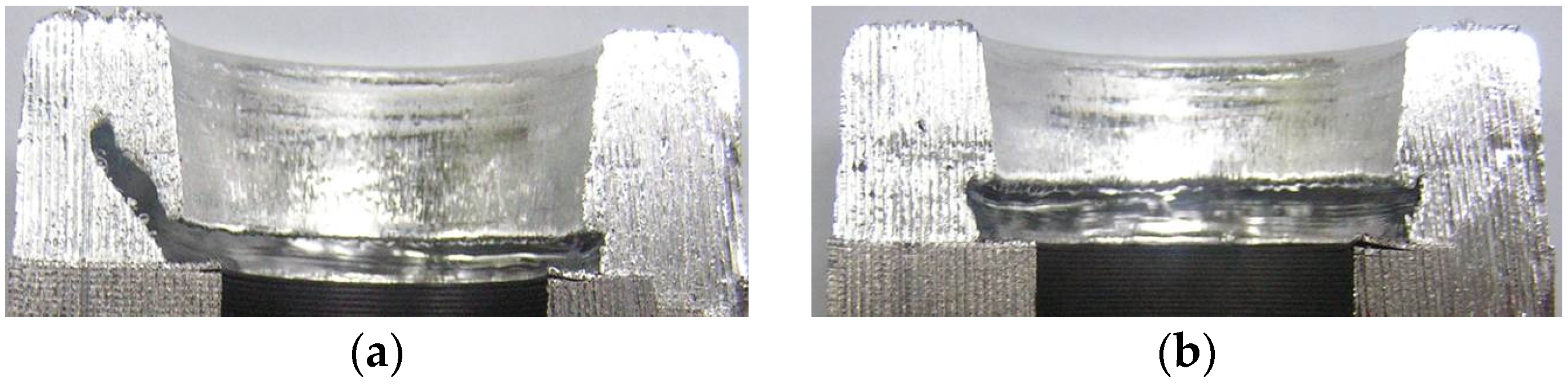
However, in the prototype rotors prepared by conventional centrifugal casting, the inner part of the upper end ring was eroded, as in
Figure 9, but that did not happen with the proposed centrifugal casting.
Table 4 compares the densities and the fill factors of the three types of rotors. Compared to those made using the conventional pressure die-casting method, the rotors made by conventional centrifugal casting method were superior in bar resistance, density, and fill factor. However, the rotors of the conventional centrifugal casting method showed a large deviation in fill factors, probably because of erosion induced by the unstable process conditions.
The proposed casting method raised the density of each part compared to the conventional centrifugal casting method, and reduced bar resistance by about 3%. In addition, the overall fill factor was improved by about 4% and the deviation in fill factor was also reduced.
Through this experiment was confirmed that rotors made by the centrifugal casting method were superior in fill factor to those made with the pressure die-casting method. Compared to the pressure die-casting method the centrifugal casting method uses a relatively lower molding pressure which enables better insulation between the aluminum and the rotor lamination, reduces rotor-slot bar resistance, and improves the fill factor of the rotor by reducing pores. Moreover, the proposed casting method minimized rotational vibrations by lowering the mold rotation speed for solidification with uniform filling of aluminum inside the rotor, and improved the overall filling state and fill factor of the conductor part of the rotor by increasing the mold temperature and delaying solidification.
4.2. Analysis of the Results of the Comparative Experiment on the Efficiencies of the SPIMs, Using a Dynamometer
This experiment applied the three types of prototype rotors to a SPIM and measured motor efficiency according to the load using a dynamometer. In order to exclude the influence of other variables related to motor efficiency except the fill factor, the experiment used the same measurement conditions for each rotor. For higher reliability of the experimental results, two stators of different specification and three prototype rotors, one of each type, were prepared for the experiment.
Table 5 shows the specifications of the prototype stators, and
Figure 10 shows prototype stators of SPIM used in the experiment.
Figure 11 is the dynamometer used in the experiment for comparing the efficiency of SPIMs.
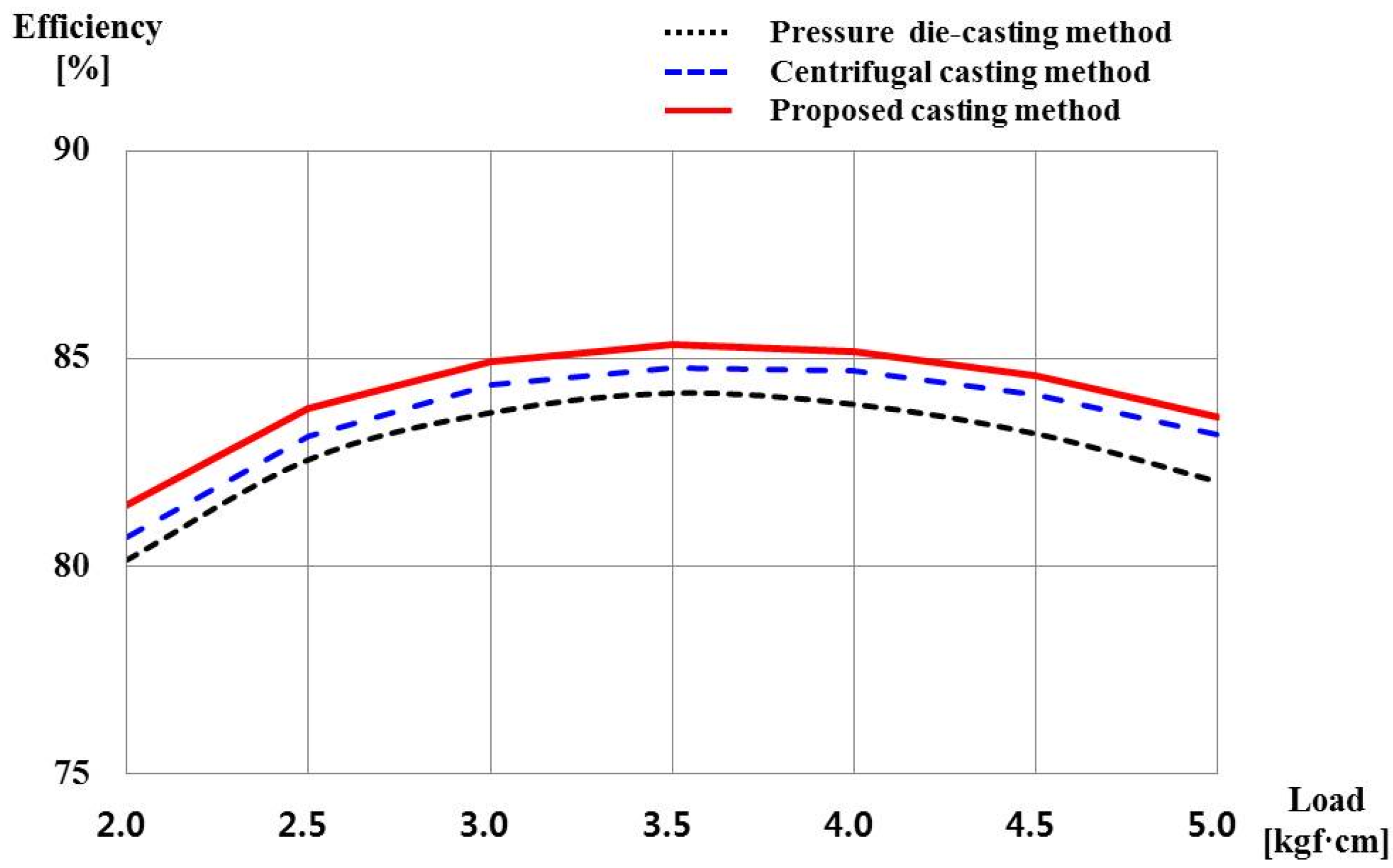
Table 6 and
Figure 12 are the results of comparing the fill factor by applying 220 V/50 Hz with the first stator. Motor efficiency was 1.4% higher with the rotors of the conventional centrifugal casting method than with those of the pressure die-casting method. In the torque properties, the starting torque decreased by 0.26 and the maximum torque increased by 0.2, with the advantage going to the centrifugally-cast rotors. Compared to the conventional centrifugal casting method, the proposed casting method improved motor efficiency by 1.2%. In addition, it decreased the starting torque by 0.12 and increased the maximum torque by 0.12.
Table 7 and
Figure 13 are the results of the same experiment done by applying 115 V/60 Hz with the second stator. Motor efficiency was 1.1% higher with the rotors of the conventional centrifugal casting method than with those of pressure die-casting method. In the torque properties, the starting torque decreased by 2.8 and the maximum torque increased by 0.1. Compared to the conventional centrifugal casting method, the proposed casting method improved motor efficiency by 0.7%. In addition, it decreased the starting torque by 0.18 and increased the maximum torque by 1.1.
Summing up, the enhanced aluminum fill factor of the rotor reduced the input power of the SPIM and increased the rotation speed, and as a result, the efficiency of the SPIM was improved by 2%, and torque was also enhanced by the reduced rotor-bar resistance.
4.3. Analysis of the Results of the Comparative Experiments on the Performance of a Refrigerator Compressor, Using a Calorimeter
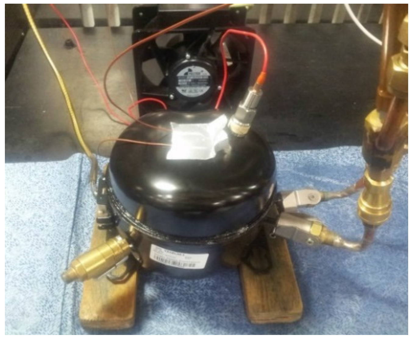
This experiment applied rotors with improved fill factors to a refrigerator compressor, and tested the benefits of the improved rotors. With the SPIMs used in the efficiency test above, a single-phase hermetic reciprocating compressor was prepared as in
Figure 14.
In addition, its power consumption and performance (refrigerating capacity) were tested using a calorimeter as in
Figure 15.
The rotation speed of the motor inside the compressor was measured using a vibration sensor, and the refrigerating capacity was measured according to the ASHRAE L.B.P test conditions [
24,
25,
26].
The results confirmed that power consumption was lower and refrigerating capacity was higher in a compressor using a rotor with a high fill factor. As in the results of the experiment using a dynamometer, these results confirmed that the starting properties of the SPIM are improved when the fill factor of the rotor is high, and the improvement is reflected fully in the performance of the refrigerator compressor. That is, the reduced input of the SPIM also lowered the power consumption of the compressor, and the starting properties were improved by a higher rotation speed, which consequently facilitated heat release inside the compressor and improved the performance of the compressor.
5. Conclusions
This study was conducted in order to improve the fill factor of the conductor part of the rotor, for higher efficiency of SPIMs applied to refrigerator compressors.
First of all, using a FEM analysis program the effect of the rotor fill factor on the properties of the SPIM was tested with regard to the casting method. And, encouraged by the analysis results, we fabricated rotors using the conventional pressure die-casting and centrifugal casting methods and also by our proposed improved centrifugal casting method. The resultant fill factors for the conductor parts of the rotors for each of the casting methods were compared. Moreover, prototype products were prepared with the three different casting methods, and with a dynamometer the efficiencies of the SPIMs with the prototype rotors were measured and compared. In addition, the prototype products were installed in a compressor and with a calorimeter the performances of the compressor with each of the prototype products were measured and compared.
From the results of these experiments it was confirmed that when an improved rotor with a high fill factor due to the use of the proposed casting method was used, increased efficiency of the SPIM and increased refrigerating capacity of the compressor were the results.
In addition, pressure casting was popular in the past because it was advantageous in terms of production, initial investment cost, etc. As confirmed by the experimental results, however, the fill factor of finished products is low and this lowers efficiency. Moreover, the loss of materials is large in pressure casting because a relatively larger amount of scrap is generated than in centrifugal casting due to the characteristic of the manufacturing process. For the long run, therefore, centrifugal casting is considered more cost-effective as it reduces the loss of materials.
In conclusion, the results of the FEM analysis and the experiments of this study prove the reliability and validity of the proposition that the casting method proposed in this study improve the fill factor of the rotor, and consequently, the performance of SPIMs. Based on the outcomes of this study, we surmise that it is advisable to continue technological development and research toward reducing rotor-related power losses and enhancing the efficiency of SPIMs.


