1. Introduction
Cogeneration represents the thermodynamically sequential production of two or more useful forms of energy from a single primary energy source. In the Russian Federation, cogeneration is typically defined as a centralized electricity supply scheme with a single turbine unit supplying electricity and heat. In the thermodynamic sense, cogeneration is based on extraction steam turbines that reuse heat extracted from the cycle, in contrast to the separate process layout with condensation turbine units generating electricity and boiler units supplying heat. The associated energy efficiency gains are realized mostly by substituting used heat coming from the steam cycle of the thermal generation unit for the heat that would have to be supplied by the boiler house in the separate layout. This eliminates the waste heat that an electric power plant would release into the environment upon converting the chemical energy of burnt fuel into electricity. The physical cost of the allocation method attributes economic gains to fuel savings on electricity generation, as the amount of fuel consumed on electricity generation is reduced by subtracting from it the equivalent heat content of condensate delivered to power-generating boilers of the power plant and the amount of heat supplied by the heating unit to external consumers. By leveraging the combined production of electricity and heat, instead of separate production, a power plant can cut its fuel needs by about 30%. Therefore, expanded use of cogeneration based on heat-generating turbine units offers a clear path toward improved heat utilization in power utilities.
As the experiences of Denmark, Finland, and Russia demonstrates, up to 90% of cities’ needs for heat and electricity can be met by producing both commodities in a single cycle. The European Union has adopted a directive on the promotion of cogeneration that sets target of 18% of total electricity output. However, its implementation is hindered by the enormous cost of securing right-of-way for heating lines and the difficulty of convincing consumers to switch to centralized heating. None of these problems is observed in Russia where urban developers always have cogeneration in mind. As early as in the 1920s, the State Plan for Electrification of Russia (known as GOELRO) supported and put in place the decision to use combined heat and power (CHP) plant for electricity and heat production in Russian cities. For Russian power utilities’ businesses, utility grids connecting joint consumers of electricity and heat in Russian cities may be seen as their most valuable asset [
1,
2].
The advent of new economic conditions did not render cogeneration obsolete by any means [
3,
4]. Due to Russia’s severe climate, heat consumption exceeds electricity consumption by a factor of two while the total capacity of centralized heating systems in Russia exceeds the combined capacities of the rest of the world. District heating is a stable sector of the power utilities market.
The Russian Federation’s generating mix is presently dominated by traditional steam-power cycle systems. Among them, about half of the annual power output is actually covered by CHP generating capacity. Roughly 65% of cogeneration units are concentrated at CHP plants with primary steam pressures of 13 MPa. A significant fraction of the remaining units (about 22%) is represented by less efficient CHP facilities rated for steam pressure of 9 MPa or lower. Citing a general assessment of cogeneration plants from 2015 [
5,
6], oil-gas and pulverized-coal CHP facilities are estimated to be worn down by 58% and 48%, respectively. Given these numbers, upgrading the industry’s capacities for improving the efficiency of cogeneration turbine units becomes a matter of first priority. A visible growth in the number of combined-cycle (CC) gas-and-steam units [
5,
6,
7,
8] fails to relieve this problem as such units are inferior to classical CHP as heat generators and are only efficient when their operating schedule emphasizes electrical load over heating load.
The choice of the heat supply process scheme factors into the operating efficiency of cogeneration units [
9,
10]. Data on externally-caused variations of electrical and heating loads can be used to optimize the heat supply process design which can then be translated into specifications for upgrading the extraction steam turbine to maximize its thermal efficiency throughout the year. The main goal of this paper is to explore the choice of the best process design for supplying heat to Russian municipal heating systems in a market environment. We set thermal efficiency of cogeneration units computed in terms of fuel consumption as our primary benchmark.
2. A Survey of District Heating Systems in Russian Cities
As noted above, the Russian cogeneration industry, based on centralized district heating, is by far the largest, exceeding the total for the rest of the world in terms of installed capacity. Combined heat and power (CHP) plants form the core of this large-scale system.
The following features are shared by most urban cogeneration facilities across the Russian Federation [
11]:
District heating lines are largely worn out;
Most CHP plants are about to exceed (or have already exceeded) their designed fleet life;
Some CHP units actually operate as large-scale boiler houses with only minor electricity production;
State-regulated prices for heating versus market pricing for electricity;
Consumer base is dominated by households and commercial real estate, as a number of major industrial consumers either abandon centralized heating due to the utility rate policy or relocate their manufacturing operations out of the city;
The introduction of more stringent energy efficiency requirements for buildings and structures reduce the demand for heating in cities, despite the continuing trend toward urban densification;
Highly uneven daily pattern of electric energy consumption.
Reduced consumption of heat, coupled with tight regulation of the heating market, has forced a number of CHP facilities designed to operate at their peak heating load into suffering recurring losses. In the electricity markets, CHP generators are price-takers, meaning that they have to accept whatever price the market comes to in a particular time. When a CHP plant is operated in cogeneration mode to produce thermal and electric energy simultaneously, it has the liberty to shift its costs between the two energy products, enabling it to offer electricity at a price low enough to win a slot in the trading schedule. However, as it switches to condensation mode for the summer, its electricity output becomes rather expensive and may only catch a bid in the market in times of peak electricity consumption. A small CHP plant may raise the overall market price by 10%–15% in peak periods [
12,
13].
Steam-turbine CHP facilities that can be extensively found in Russian cities are poorly suited for controlled electricity output in the heating season as they are required to maintain a sufficient flow of steam through the turbine to supply consumers’ heating needs. This control issue becomes even more complicated if there are no steam boilers at the CHP plant. This means that such facilities often find themselves unable to fulfill a System Operator’s request in response to uneven electricity consumption, lagging in times of peak consumption when electricity is priced expensively in the market. At the same time, when electricity demand enters its overnight trough, this unwieldiness of a CHP plant (the inability to reduce electricity output while supplying a constant heating load) causes electricity prices to drop (sometimes right down to zero) in the market.
It can be concluded that cogeneration systems in Russian cities with CHP at their core share the common problem of their power-generating assets being poorly adjusted in terms of structure and capacity to the demand for thermal and electric energy in heating and electricity markets and, therefore, are in need of a major upgrade. New model regulations for heating and electricity markets that are currently drafted should provide the correct incentives to market participants so as to enable them to build reliable, agile, and cost-saving systems capable of maintaining the proper balance across all kinds of energy resources. Thence, the research of the efficiency improvement options for heating and electricity generation is timely. This becomes a matter of top importance for end-of-life CHP plants in need of reconstruction and technology upgrade.
3. Overview of Cogeneration Steam-Turbine Unit Operation Modes
Extraction steam turbines are designed for a number of operating modes chosen depending on seasonal temperature variations. These modes fall into two large categories of cogeneration and condensation.
In cogeneration mode, two products—thermal and electric energy—represent an output. This mode can be generally subdivided into winter, transitional (spring/fall), and summer modes with thermal energy and electricity output codetermined differently by the production program. The condensation mode produces no thermal energy for the consumer as its only product is electric energy.
The choice of modes is further affected by a number of process constraints [
14,
15]:
Service water flow rate though reheaters: The flow rate of service water through inline reheaters must be maintained within specific lower and upper bounds that are determined by hydraulic operating considerations and heat-exchange conditions.
Service water pressure: Pressure limits are set in order to prevent service water from boiling inside inline reheated pipes.
Maximum extraction temperature for the top inline reheated: There is a limit on the allowed extraction temperature for the top inline reheaters so that working vanes of final stages upstream of the extraction sections will not be subjected to excessive flexion stresses.
Maximum thermal energy output: This limitation stems from the maximum permitted pressure in heating extraction chambers.
Indirect electric power output control: When a cogeneration unit operates under a heating schedule (to supply a heating load), its electric power output cannot be controlled directly.
Boiler unit utilization: Solid fuel-fired boiler units may operate at loads down to 60% of their rated capacity while the load on units using gaseous fuels may be decreased to 40%.
Steam flow rate at low-pressure (LP) turbine cylinder inlet. In the maximum heating load mode, steam cannot be extracted for inline reheaters as about 4% of the flow rate in the turbine head must be directed into the LP cylinder to cool down working vanes. A cooling system for final stages may be devised as an alternative.
These operating constraints owe themselves to operational reliability of steam-turbine cogeneration units. As much as 20% of cogeneration unit failures involve invalid generating unit operating modes [
14,
16].
The heat supply process design is an important overall consideration in the improvement of turbine unit operational efficiency. Objectives that are to be addressed by steam turbine unit upgrades at cogeneration plant include determining the optimum heat supply process design and operating conditions depending on external changes in thermal or electrical loads increasing their thermal efficiency throughout the year, as well as partially relieving the above-listed limitations.
4. Overview of Heat Supply Process Designs
Major heat supply process designs currently in use include the following [
17,
18,
19]:
Cogeneration units also differ structurally. The following unit types may be identified [
20,
21]:
Back-pressure turbine units;
Extraction steam-turbine units; and
Turbine units with industrial extraction.
Heat supply processes influence structural design of turbine units and their price to a great extent. The introduction of a heat extraction location for system water reheating invites the following consequences [
18,
20]:
Longer, heavier rotor due to the introduction of a cogeneration extraction chamber translating into higher capital costs of manufacturing;
Increased expenses on auxiliaries (inline reheaters, inline pumps, drain pumps);
More expensive extraction pipeline steelwork due to the need of combining an adjustable cogeneration heat extraction location with a regeneration system extraction location;
More complex steam turbine control design, including the need to deal with the problem of installing inline heaters in the turbine hall.
Multi-stage service water reheating designs additionally include cogeneration extraction chambers, meaning even greater turbine unit dimensions and capital outlays.
At the same time, the economy of the heat supply process designs are affected to a great extent by outdoor air temperature and service water flow rate. As the outdoor air temperature varies, the heating load on extraction locations fluctuates similarly, together with direct and return water temperatures, giving rise to a so-called “temperature schedule” of the heating system, a distinct pattern for every consumption site.
Depending on the thermal schedule of a system, three areas may be identified where these parameters will exhibit variation [
18,
22]:
The area with two heater units and peak boilers in operation. This area features constant heating load at extraction locations, the only variable being system water temperature that is controlled by varying extraction pressures. The turbine unit is only controlled by the heating load schedule. Lower pressure at the extraction location results in increased turbine output power and reduced specific heat release rate.
The area with two heater units in operation (peak boilers offline). In this area, both heating load at extraction locations and system water temperature vary. The turbine may operate under both heating and electrical load schedules. In the former case, electric output power decreases in response to the reduced heating load; in the latter case it increases. Consequently, a reduced heating load means a lower specific heat release rate under the heating load schedule or a higher heat release rate under the electrical load schedule.
The area with just a single heater unit in operation. The turbine may operate under both heating and electrical load schedules in this area. The turbine will operate like in the second area until the minimum pressure is reached in the extraction location. Upon reaching the minimum pressure in the extraction location, the turbine will transition into the diaphragm-controlled natural pressure increase mode. The pressure at the extraction location varies depending on the amount of steam coming in through the open diaphragm. Increased pressure in the extraction location reduces electric power output while increasing the specific heat release rate.
Throughout a year, an extraction steam turbine mostly operates under the heating load schedule. There is no fixed service water flow rate as it varies depending on season and the heat consumers’ demand. Increased flow rate through inline heaters with a service water temperature remaining constant results in a higher heating load. Upon reaching the maximum heating load of the turbine unit (at maximum pressure in cogeneration extraction locations) the peak boiler goes online. With a system water flow rate high enough, the peak heating load can be reached even though the outdoor air is only moderately cold.
Due to the expenses associated with putting peak boilers online to accommodate high heating loads throughout the year, heat supply designs with multi-stage controlled steam extraction locations may still offer a cost advantage despite the above-mentioned drawbacks of such designs. Consequently, cogeneration units with three adjustable steam extraction points are seeing increasingly frequent discussions in the literature.
There is another process advantage with three-stage service water reheating: in theory, the application of a cogeneration unit with three controlled steam extraction points should mean less fuel expended on electricity generation compared to classical designs, with the heating load being the same. Computations in support of this hypothesis will be provided further below.
5. Problem Formulation and Input Data
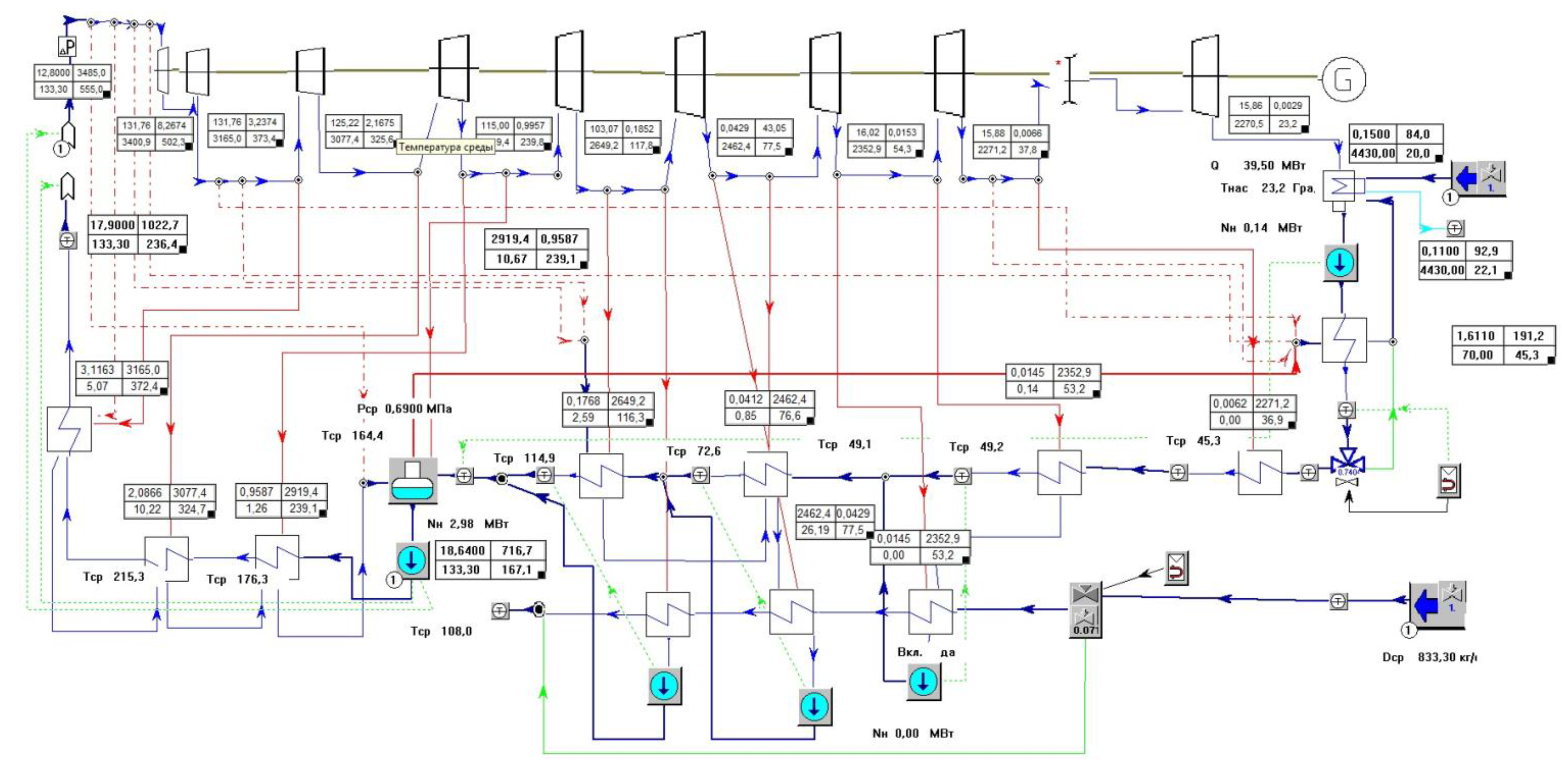
To verify the hypothesis put forward in the preceding section, we shall consider a T-110/120-130 turbine manufactured by the Ural Turbine Works used with various heat supply process designs.
The T-110/120-130 turbine is the most popular brand of cogeneration turbine units in the Russian Federation, with more than 300 turbine units in operation throughout the country. The thermal design concept of these units is described in scientific literature [
18,
23,
24,
25,
26].
The classical thermal design of these turbine units features multi-stage system water reheating and includes two inline reheaters: PSG-1 (extracting steam from the bottom cogeneration extraction location downstream of Stage 23) and PSG-2 (extracting steam from the top cogeneration extraction location downstream of Stage 21). A rotary diaphragm upstream of the turbine Stage 1 LP cylinder controls the heating load. The turbine unit operates under system heating load schedule most of the time using one (the bottom), or both, of the inline heaters. Key specifications of the T-110/120-130-5 units are presented in
Table 1.
Let us consider three thermal design layouts of a cogeneration unit with multi-stage controlled steam extraction:
Standard thermal design with two inline reheaters and a rotary diaphragm controlling the heat supply (
Figure 1);
Thermal design with three inline reheaters and a rotary diaphragm controlling the heat supply (
Figure 2); and
Thermal design with three inline reheaters and a quantitative-qualitative heat supply control (uncontrolled extraction) (
Figure 3).
Thermal load regulation is distinguished by its method: qualitative, quantitative, or quantitative-qualitative heat supply control. The essence of the methods of regulation follows from the heat balance equation. Qualitative regulation is based on regulating the heat supply by changing the temperature of the coolant (the coolant flow rate remains constant). Quantitative regulation is based on the regulation of heat supply by altering the coolant flow at a constant temperature. Finally, quantitative-qualitative regulation is based on the regulation of the heat supply through the simultaneous change of the flow and the temperature of the coolant.
Presented below are the respective turbine unit simulations produced using Boiler Designer (Optsim-K, Moscow, Russia), a software tool for designing heating installations and finalizing them with static and dynamic computations.
Our comparative evaluation of cost efficiency of these heating process designs will involve:
Thermal design computations in Boiler Designer;
Reviewing a standard turbine unit design, including the effect of outdoor air temperature, service water flow rate, and turbine unit operation modes throughout the year;
Reviewing modified thermal designs allowing for increased number of controlled extraction locations and heat supply through uncontrolled extraction locations, while maintaining the specified temperature schedule by adjusting system water flow rate at inline heaters; and
Completing a comparative analysis of the thermal efficiency of turbine unit thermal design layouts based on thepreceding computations.
We will assume the following identical operating conditions of the turbine unit to allow for comparison of our findings from thermal design computations:
Turbine unit operating under heating load schedule;
Average temperatures over the year (°C): −20; −15; −10; −5; 0; +3; +5; summer mode. The unit switches to summer mode at temperatures greater than +8 °С, with the system water flow rate dropping by a factor of three. At environment temperatures below −20 °C the temperatures of direct and return water are 130 °C and 70 °C, respectively;
The prevalence of various temperatures over the year is indicated using a temperature distribution histogram for the city of Moscow and the Moscow Province (
Figure 4);
All thermal designs have identical annual heat supply rates;
A constant system water flow rate is maintained at inline reheaters (3000 t/h when operating under the heating schedule, 1000 t/h in the summer mode); and
The lower threshold for generating unit unloading is determined by the lower boundary of the boiler unit control range.
We will assume the specific fuel consumption rate for electricity production as a benchmark for choosing the most cost-efficient turbine unit thermal design given identical heat supply parameters. Electricity output will vary depending on the choice of thermal design.
6. Computation Procedure
We employed the Boiler Designer software (Moscow, Russia) for numerical simulation of thermal designs (
Figure 1,
Figure 2 and
Figure 3) and estimation of their design and cost efficiencies. A brief summary of the simulation approach follows with a brief account of supporting formulas.
The simulation of T-110/120-130 generation unit thermal designs starts with boiler specification and the choice of fuel type. We selected the BKZ-500-140-1 boiler manufactured by Open Joint-Stock Company (OJSC) “Sibenergomash” with a gross efficiency of 88%. It is assumed that the unit is fired with solid fuel (coal) with a process combustion heat output of 3740 kCal/kg (15,670.6 kJ/kg).
The steam-power turbine, being a cogeneration turbine, is expected to operate mainly under the temperature schedule of the heating system depending on the outdoor air temperature. Direct and return water temperatures were specified using the temperature schedule of the heating system (130 °C and 70 °C, respectively) and the temperature distribution histogram for Moscow city/province (see
Figure 4).
System water enthalpies, saturation temperatures, and pressures inside the housing were computed along with sub-cooling values using balance equations and properties of the heating medium for surface horizontal inline reheaters. In turn, sub-cooling for reheaters depends on the system’s temperature schedule and water flow rate [
16,
18,
26].
These steps were followed by computations for regenerative extraction locations and the flow-through part of the turbine. Flow rates of extraction steam and its condensate were found by solving material and thermal balance equations for reheaters. The resulting steam flow rates in reheaters and steam leakage rates through turbine seals were used to arrive at the flow rate of steam in turbine sections.
Various thermal designs of the unit were then evaluated to compute their thermal efficiency parameters: heat release rate to the turbine unit and inline reheaters, heating load on in-line reheaters, turbine unit efficiency (with combined production of electricity and heat (total) and on electricity production alone), the specific heat expended by the turbine unit per unit electricity production, the specific amount of steam expended by the turbine unit, and the specific electricity generation rate in the cogeneration cycle with external consumption of heat.
The efficiency of a turbine unit with a generator for combined production of electricity and heat transferred to system water is computed using the formula:
where
QIRH is the heating load on inline reheaters (kW);
PE is the electrical power on generator terminals (kW); and
QTU is the rate of fuel energy consumed in the boiler of the cogeneration system for the production of electricity and heat (kW).
The efficiency of a turbine unit with a generator for electricity production is computed as follows:
where
PP is the electricity demand of plant auxiliaries (kW);
is the rate of fuel energy consumed in the boiler of the cogeneration system for the production of electricity (kW); and
is the rate of fuel energy consumed in the boiler of the cogeneration system for the production of heat (kW).
Thermal efficiency indicators are calculated in accordance with the physical method (also known as the energy method) of the distribution of energy costs (fuel) in cogeneration units. Fuel consumption, or its equivalent heat consumption for power generation, is obtained by subtracting from the total amount of heat supplied to the cogeneration unit, the amount of condensation heat directed in the power boilers of the CHP, and the amount of heat from the cogeneration unit supplied to external customers. In other words, the fuel economy in the production of electricity and heat in the combined cycle refers to the electrical energy.
The specific rate of fuel energy consumed in the boiler for electricity production (kWh/kWh (net)) is determined using the formula:
The following ratio is useful for determining the unit’s specific steam consumption rate (kg/kWh):
where
D0 is the primary steam flow rate (kg/h).
The specific electricity output in the cogeneration cycle (kWh/kWh) is determined using the relation:
where
is the electric power output by cogeneration steam flows (kW);
, the mechanical efficiency of the turbine;
, the mechanical efficiency of the electric generator;
, the consumption of heating steam in the reheaters (kg/s); and
, the heat drop in the compartments of the turbine (kJ/kg).
Thermal efficiency computations for the power plant unit in general follow. They include the boiler heating load, the heat transportation efficiency of steam main lines and fuel heat release rate. These indicators support fuel consumption rate computations for various thermal designs of the turbine unit: relationships presented below were used to that end:
Fuel consumption rate in boiler (kg/s):
where
is the lower heating value of the fuel (kJ/kg).
Fuel consumption rate attributed to electricity production (kg/s):
where
,
are relative efficiency factors referring the equipment to state-of-the art designs (the boiler unit and pipelines accordingly) [
18,
20].
Fuel consumption rate on heat production for turbine heat extraction locations (kg/s):
Specific fuel consumption rate attributed to the heat transferred to system water in inline reheaters (kg/kJ):
Specific fuel consumption rate attributed to electricity production (kg/kWh net):
The net electricity production efficiency of the unit is determined using the following relation:
7. Main Findings from Computation
A plot of specific gross fuel-equivalent consumption rate as a function of outdoor air temperature for T-110/120-130 unit thermal designs in question (
Figure 1,
Figure 2 and
Figure 3) with service water flow rate of 3000 t/h is shown in
Figure 5.
The plots show clearly that, assuming the specified system water flow rate, the design based on three in-line reheaters and controlled cogeneration extraction locations enables electricity generation costs (in terms of fuel consumption) to be minimized at below-freezing outdoor air temperatures. At temperatures above freezing, the extraction for heating is disengaged, and the heating load is maintained for the specified system water flow rate. Beyond that point, specific consumption rates of the three-reheated design match those from the standard design. This design further increases the turbine unit’s thermal energy release capacity, meaning that more expensive peak boilers will have to be brought online at temperatures lower than those in the standard design. At the same time, the three-reheated design with uncontrolled cogeneration extraction locations is found to be inefficient at specified water flow rate.
In addition to the outdoor air temperature, the heating load is also a function of the system water flow rate. The efficiency of heat supply process designs will vary depending on the heating load. Let us analyze heating designs in terms of electricity generation efficiency as a function of system water flow rate given different outdoor air temperatures.
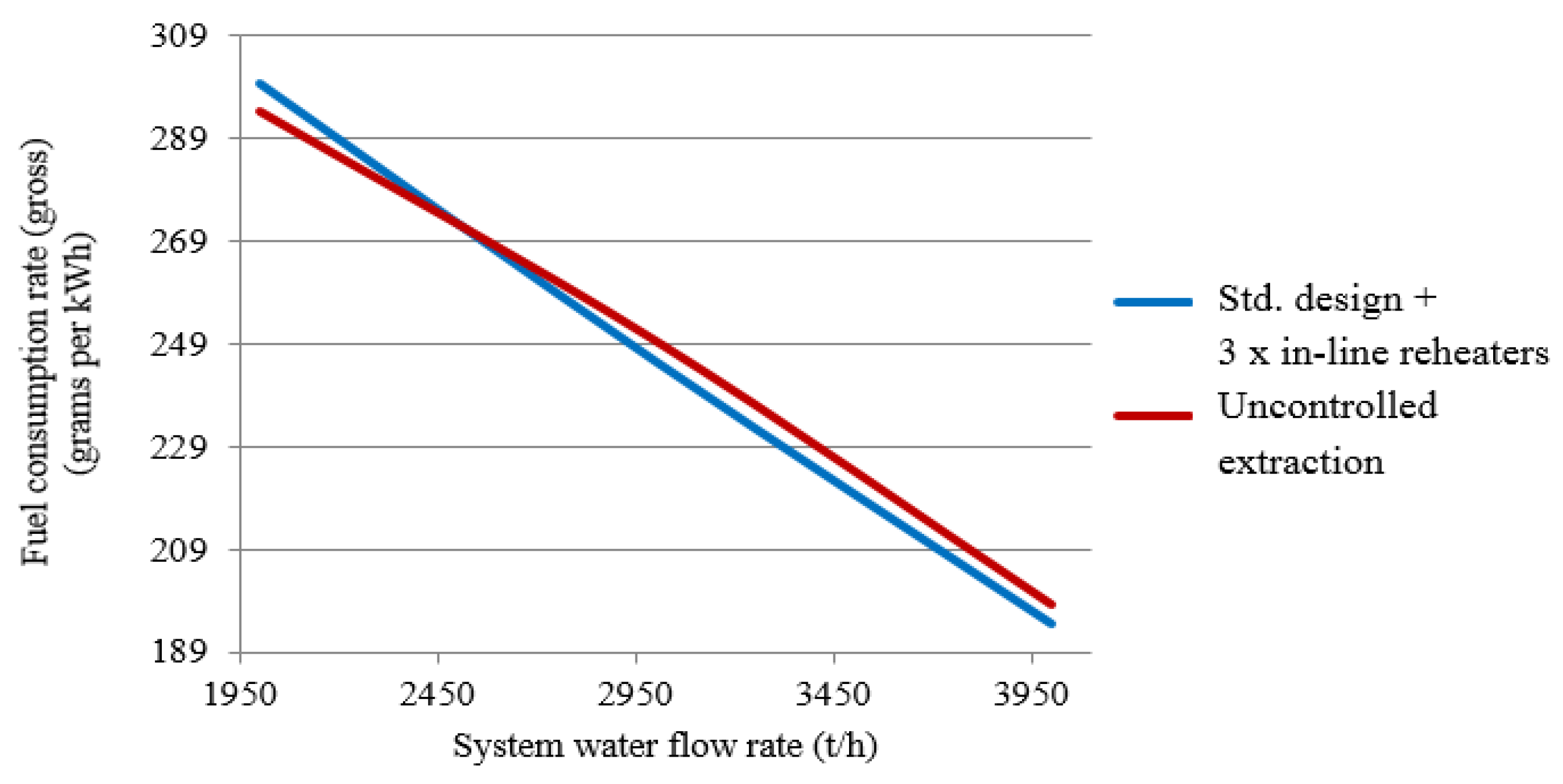
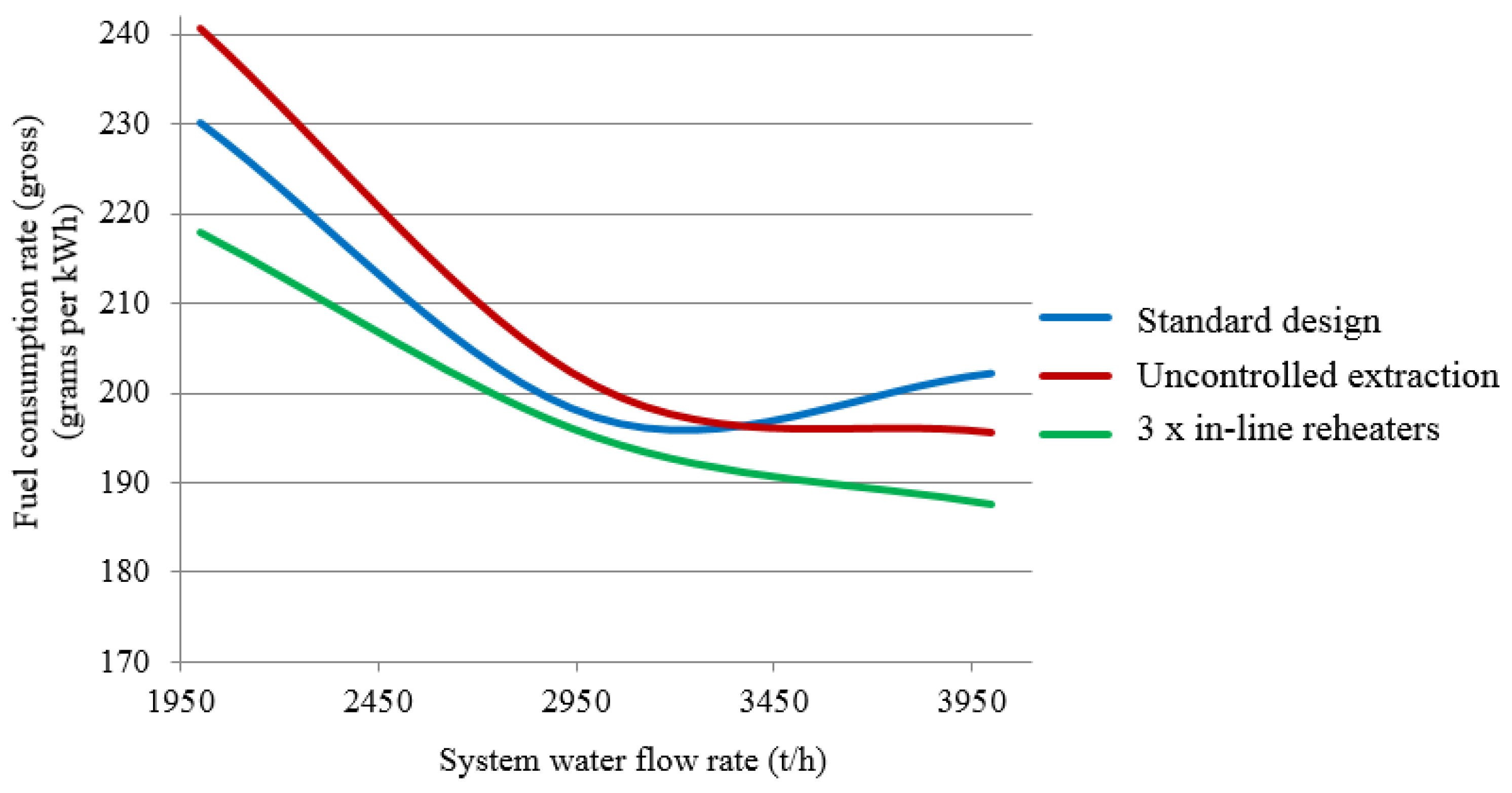
Figure 6 plots fuel-equivalent consumption rates for electricity generation as functions of the system water flow rate for the standard design and designs featuring three inline reheaters with controlled and uncontrolled cogeneration extraction locations assuming a fixed outdoor air temperature of +5 °C. As the heating load is maintained at this temperature across a range of water flow rates without having to bring an extra inline reheated online, the respective plots for the three-reheated design with controlled extraction will match those for the standard design.
These plots show that reduced heating load (system water flow rate) causes the design with three inline reheaters and uncontrolled cogeneration extraction locations—previously found to be inefficient—to have a lower specific fuel consumption rate on electricity generation. Increased heating loads strip the thermal design with uncontrolled extraction locations of its benefits.
Figure 7 and
Figure 8 show plots of specific fuel-equivalent consumption rates for electricity generation as functions of system water flow rates for the standard design and three-reheated designs with both controlled and uncontrolled steam extraction at outdoor air temperatures of +3 °C and 0 °C, respectively. The heating load is similarly maintained in this case without having to bring an additional inline heater up; the consumption rates for the three-reheated design with controlled extraction match those of the standard design.
At lower outdoor air temperatures, the relationships become manifestly non-linear. It is evident that increased heating load makes the uncontrolled extraction design suffer from a significant increase in the specific rate of fuel consumed on electricity generation compared to the standard design.
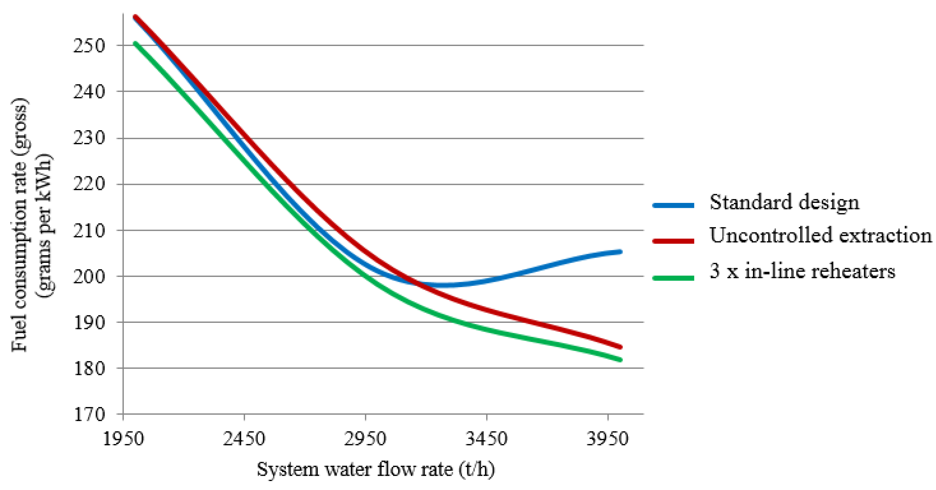
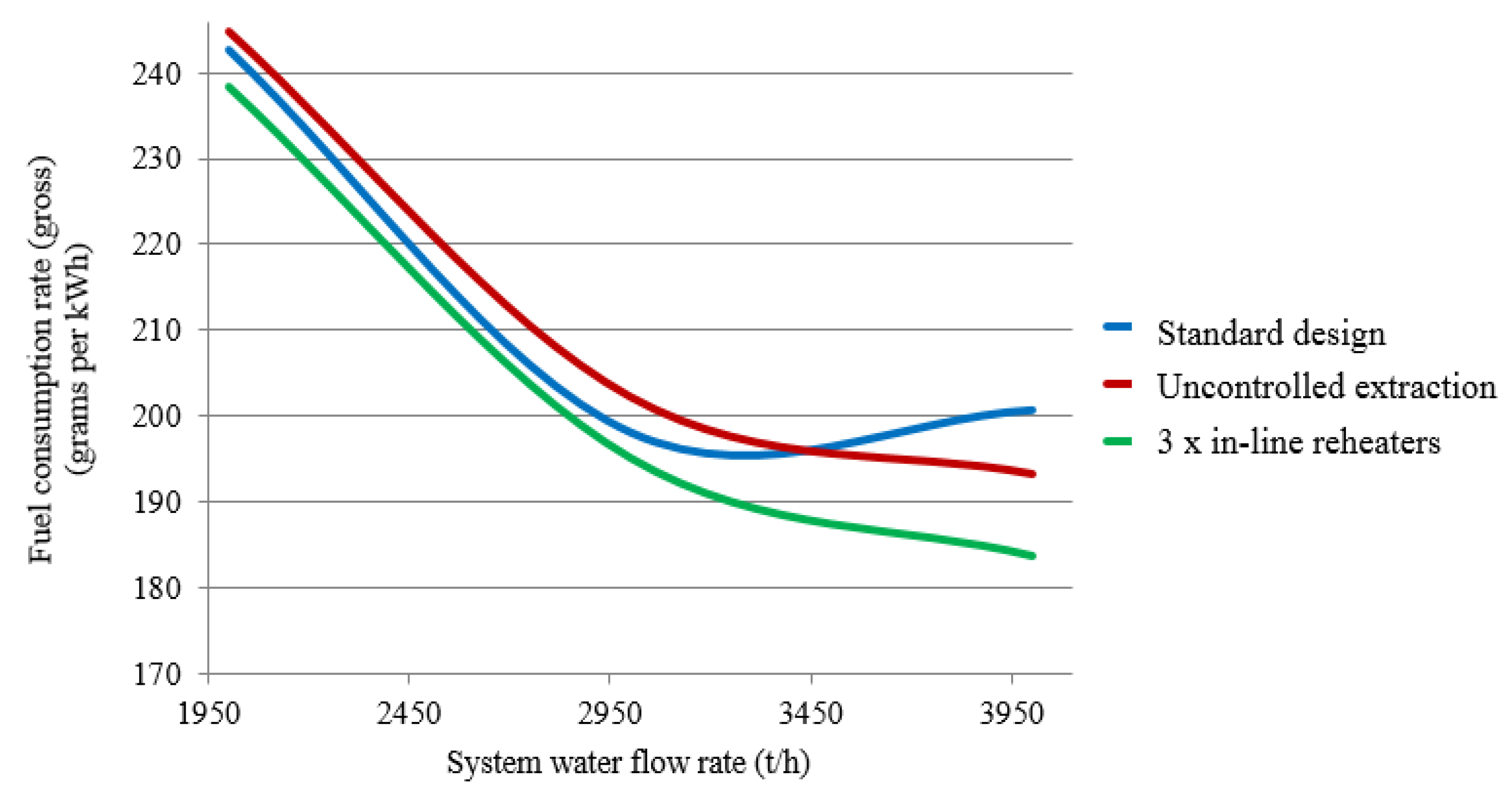
Figure 9 and
Figure 10 show plots of specific fuel-equivalent consumption rate for electricity generation as functions of system water flow rates for thermal designs under study at outdoor air temperatures below freezing (−5 °C and −10 °C). The heating load increases dramatically, prompting the use of an additional in-line reheated. In contrast to the preceding cases, the fuel consumption behavior of the three-reheated design with controlled extraction will deviate from that of the standard design.
The plots show that bringing an additional inline heater online to accommodate increased heating load improves the efficiency of three-reheated designs. While the three-reheated design with controlled extraction is a clear winner in terms of specific fuel consumption for electricity generation across the entire range of system water flow rates, the issue is far from settled for the three-reheated design with uncontrolled extraction. This design only becomes more energy-conserving when the system water flow rate is high enough. That said, lower outdoor air temperatures push the system water consumption rate threshold even further, which must be exceeded for the uncontrolled extraction design to have any advantage over the standard cogeneration design. This conclusion is also supported by plots of specific fuel consumption rate for heating designs operating at −15 °C outdoor air temperature (
Figure 11).
Let us evaluate the efficiency of heating designs as the turbine unit is operated throughout the calendar year. Assume two cases for the summer season:
Both the boiler unit and the turbine unit work in the summer under the electrical grid schedule with boiler unit operating close to its rated load; and
The boiler unit is unloaded to its process minimum (60%) and operates in this mode throughout the entire summer period.
Proceeding from the specified initial conditions, we assume that the rated system water flow rate of 3000 t/h specified for the heating schedule decreases to 1000 t/h when switching to the summer mode. Assume that the turbine unit is brought offline for scheduled maintenance for 30 days (720 h) in the summer. Findings from the turbine unit thermal design efficiency computations at specified initial conditions for two summertime operating scenarios are summarized in
Table 2 and
Table 3.
These findings show that if turbine unit thermal designs are assessed in terms of their year-round efficiency, the design with a three-stage heating of system water from uncontrolled extraction locations promises the greatest savings as expressed in the specific rate of fuel consumption on electricity generation. This is due to the fact that computations have been performed for Moscow’s temperature pattern with a mean annual temperature around 4 °C. Prolonged periods of moderate heating load have made the uncontrolled extraction design to emerge as an efficiency champion—even with 30-day planned downtime in the summer. The summer period with its minimum heating load offers the best opportunity for application of this design.
Operating the turbine unit under the electric grid schedule over the summer impairs its efficiency regardless of the choice of any particular design surveyed here. Designs based on three inline reheaters show some advantage in this respect when operated as a turbine unit throughout the year while passing the summer period in this mode. The turbine unit with uncontrolled extraction provides the greatest annual fuel savings as far as electricity production is concerned.
Even as the boiler unit is unloaded for the summer down to its process minimum the turbine unit continues to operate in the cogeneration mode. Given that the cogeneration mode is the primary mode for all turbine unit thermal designs surveyed, it results in the best performance when operating year-round. Designs featuring three inline reheaters also display an advantage here. The turbine unit with uncontrolled extraction provides the lowest annual fuel consumption rate as far as electricity production is concerned with specified initial conditions.
8. Conclusions
Cogeneration systems in Russian cities are riddled with imbalances of power equipment choices and capacities vs. market demand for heating and electricity products. This can be explained by the fact that primary cogeneration assets have been in operation since mid-20th century, having been initially designed for a planned economy. Moreover, the cogeneration system is close to the end of its productive life. Overall, it seems that cogeneration systems are in a need of a major upgrade.
Furthermore, cogeneration systems in Russia are built around CHP plant concentrating cogeneration units that simultaneously produce commercial heat and electricity. CHP facilities supply about 50% of the total annual electricity output, while their share in heat production exceeds 30%.
As primary CHP assets near the end of their useful life, it becomes a matter of foremost importance to upgrade their technology and equipment while striving for improved efficiency of cogeneration turbine units.
The operating efficiency of a cogeneration unit is determined primarily by the choice of heat supply design which has to take into account the externally-caused variation of heating demand and electric loads. The thermal efficiency of a cogeneration unit process is seen as a cost savings criterion.
This paper surveyed three thermal designs of the T-110/120-130 cogeneration turbine unit with multi-stage controlled steam deduction:
Standard thermal design with two inline reheaters and rotary diaphragm controlling the heat supply;
Thermal design with three inline reheaters and rotary diaphragm controlling the heat supply; and
Thermal design with three inline reheaters and quantitative-qualitative heat supply control (uncontrolled extraction).
These turbine unit designs have been simulated using Boiler Designer, a software tool for designing heating installations and finalizing them with static and dynamic computations.
Cogeneration unit designs have been benchmarked in terms of their thermal efficiency expressed as the rate of fuel consumption. Here, the specific fuel consumption rate for electricity production was viewed as a key parameter of thermal efficiency.
Computations performed for heat consumption patterns characteristic of the city of Moscow have shown that designs featuring three cogeneration extraction locations have an advantage over the standard thermal design when the turbine unit is operated year-round (allowing for planned downtime), enabling savings in terms of the amount of fuel burned per kilowatt-hour of electricity output. These conclusions remain valid when cogeneration units operate in the summer under the electric grid schedule or when boiler units are unloaded to their process minimum.
The best heat supply solution is provided by the combined thermal design featuring three steam extraction locations controlled by a single diaphragm and opening/closing valves at each extraction location and allowing for bypassing the inline reheaters, as well as controlling the flow rate of system water passing through.
In summer and transitional modes with modest heating loads, or when the turbine unit is operating under the electric schedule, it would be most efficient to operate with a fully-open diaphragm while controlling heat output by optimizing system water flow rates at inline reheaters (in this case heat is supplied similarly to the uncontrolled extraction case). In the winter, from the economic efficiency standpoint, it would be more reasonable to use a rotary diaphragm to control the heat supply.
In the summer mode, as well as modes with system water flow rates of 2000 t/h at temperatures (+5, +3, 0) °C, the greatest efficiency is provided by the turbine unit thermal design with uncontrolled cogeneration extraction locations. At temperatures of −5 °C or below, as well as with system flow rates of 2000 and 3000 t/h, the process design with three-stage system water reheating and rotary diaphragm heat output control has the greatest efficiency.


