1. Introduction
Three-phase grid-connected inverters have been widely employed in various applications, including renewable power generation and regenerative energy systems. This is due to the recent development trend constructing the electrical grid in terms of distributed generation (DG) systems, in which grid-connected inverters are connected in parallel with each other to form a microgrid [
1,
2]. The essential functionality of microgrids is to have the ability to operate either in grid-connected or autonomous mode in case of the absence of the main grid. Another requirement is to handle effectively the exchange of active and reactive power between the microgrid and main grid [
3,
4]. In order to fulfill the aforementioned criteria, the control strategy of a microgrid is generally designed based on three levels of hierarchical structure to provide smartness and flexibility to microgrid, which includes the primary control, the secondary control, and the tertiary control [
5]. To follow the development trend of the microgrid, the grid-connected inverter should be able to not only provide stable operation but also improve the system performance even during the presence of abnormal grid conditions. In general, the current control loop, which belongs to the primary control, is responsible for the quality of the exchanging power. According to the recently published utility interface standard regarding DG systems [
6,
7], the harmonic contents in the injected current need to meet certain current-distortion levels in order to guarantee the power quality as well as fulfill interconnection requirements. Consequently, the current control loop should be designed to ensure the effective operation of the grid-connected inverter under any operating conditions of grid.
The PI controller has been widely used as current controller in variety of inverter applications because of its simplicity and stability. The design and implementation of this controller are quite straightforward in continuous as well as in discrete-time domain [
8]. Furthermore, low computational burden of this control algorithm makes it easier to implement the whole control system with only one digital signal controller. However, despite these advantages, the PI controllers have the limitations that they are unable to cope with sinusoidal reference signals and periodic disturbances [
9]. Although the sinusoidal tracking problem can be completely solved by implementing the controller in the synchronously rotating reference frame, poor disturbance rejection capability makes the PI type controller unsuitable for current control strategy of a grid-connected inverter in the presence of the distorted grid voltages.
For the purpose of eradicating the harmonics from inverter currents, several control approaches have been proposed, which is categorized as selective and non-selective methods [
10]. Proportional resonant (PR) controller is widely used as selective harmonic compensation scheme [
11]. This controller is often implemented in the stationary reference frame and the resonant term is added to the main controller to suppress the harmonic component in the specific order. However, since this method requires separate resonant terms to compensate each harmonic component, this approach is usually considered to alleviate only a few harmful low order harmonics. When the numbers of resonant terms increase, the control structure becomes complicated or even impractical.
Other approaches to eliminate the harmonics from inverter current use nonlinear control techniques such as the sliding mode control (SMC) [
12], predictive control [
13], or repetitive control [
14]. These control strategies are often referred as non-selective method since the controllers work in wide range of frequency, in contrast to the selective method that only regulates the harmonics in some specified orders. By using such nonlinear controllers, the distorted level of inverter current can be mitigated even under the distorted grid voltages. However, the design task of a robust controller based on above techniques usually makes the system structure complicated because of the remaining problems related to those techniques such as the chattering problem in SMC, parameter sensitive in predictive control, slow dynamic response in repetitive control and so on. Furthermore, the practical complexity of nonlinear controller may degrade the performance of the controlled system. As another approach, a neural-network-based waveform processing and filtering scheme has been reported to reshape voltage or current waveforms [
15]. However, this algorithm generally requires lots of computations to be processed in real time, which increases the computational burden of main controller. Moreover, offline training is often required in this method.
Recently, a sliding mode harmonic compensation strategy based on the system model decomposition has been reported to reduce the harmful effects caused by the nonlinear controller [
16]. In this work, the system model is first divided into two using the fundamental and harmonic components. Using two decomposed models, the controllers are separately designed, that is, the controller for the fundamental term by the conventional decoupling controller and the harmonic suppression controller by SMC. To decompose the grid voltages and inverter currents into the fundamental and harmonic components, the fourth-order band pass filters (BPFs) have been employed in the harmonic extractors. As reported in [
16], even though the steady-state current responses can be quite improved with reduced chattering by adopting the decomposed model, the inverter system exhibits a slow transient response due to the sluggish dynamic characteristics of the BPF. Moreover, the slow response of the BPF may even cause the instability problem during transient duration.
In addition to current controller, the phase lock loop (PLL) also influences on the inverter currents under the distorted grid voltages. Indeed, the conventional synchronous reference frame phase lock loop (SRF-PLL) algorithm integrated with a PI controller to determine the angular displacement of grid voltage is unable to cope with high frequency disturbances due to the limitation of the PI controller. Consequently, the high frequency uncertainty caused by the distorted grid voltages has a profound effect on the determination of the angular displacement of grid voltages. The effects of distorted grid on PLL can be alleviated by reducing the PLL bandwidth. However, this results in slow dynamic response in PLL, which means that the PLL cannot track the angular displacement of grid voltages rapidly. Recent studies have proved the effectiveness of the moving average filter basis PLL (MAF-PLL) under the distorted grid voltages [
17,
18]. The main concept of the MAF-PLL is to use the MAF as an ideal low pass filter (LPF) to remove the sinusoidal components in the synchronous reference frame before the measured grid voltages are processed in PLL algorithm.
The main objective of this paper is to present a robust current control scheme for a three-phase grid-connected inverter under abnormal grid conditions like the distorted grid. The proposed control strategy is based on the system model decomposition, in which the fundamental and harmonic current controllers are designed separately. Whereas the synchronous PI decoupling controller is employed to control the fundamental current component, a predictive basis compensator is introduced to suppress the harmonic components in inverter currents. For this purpose, the harmonic contents are extracted by means of the MAFs. Furthermore, an MAF-PLL is employed to improve the detecting performance of the conventional SRF-PLL. Also, a simple modification method to improve the transient current response is presented by changing the q-axis and d-axis harmonic currents only during the transient period of the MAF. As a result, the proposed control scheme can effectively control a grid-connected inverter during steady-state as well as transient periods even under the distorted grid voltages.
This paper is organized as follows:
Section 2 presents the mathematical system model as well as the decomposition method.
Section 3 describes the proposed control scheme composed of the PI decoupling controller, MAF-based harmonic extractor, MAF-PLL, and the predictive basis harmonic compensator. Simulation results are presented in
Section 4. Afterwards, the experimental results are provided in
Section 5. Finally, the conclusions are given in
Section 6.
2. Modeling of a Grid-Connected Inverter
Figure 1 shows a whole configuration of three-phase grid-connected inverter with an
L filter. The analyses for current controller in inverter with an
L filter are still valid for the case with
LCL filter as long as the control bandwidth is kept below resonant frequency of
LCL filter [
19]. Considering the filter inductance of
L and the filter resistance of
R, the voltage equations of a grid-connected inverter are expressed in the synchronous reference frame as follows:
where
and
are the
q-axis and
d-axis inverter currents, respectively;
and
are the
q-axis and
d-axis grid voltages, respectively;
and
are the
q-axis and
d-axis inverter output voltages, respectively; and
is the grid angular frequency.
When phase voltages and currents include harmonic components, the transformed variables into the synchronous reference frame are not in pure direct current (DC)-quantity. Instead, they contain the harmonic components as well as DC-quantity. To apply the decomposition method, the voltage and current variables can be expressed with DC-quantity and sinusoidal harmonic terms as follows:
where the capital letter
V,
I, and
E denote the inverter voltages, inverter currents, and grid voltages having DC-quantity, respectively, the subscript
“qd” denotes the variables on the
q-axis and
d-axis in the synchronous reference frame, the subscripts
“h” denotes harmonic quantities.
The decomposed models for the voltage equations of a grid-connected inverter are derived by substituting Equations (3), (4), and (5) into Equations (1) and (2) as follows:
Voltage equations in Equations (6) and (7) can be rewritten with respect to the DC-quantities and harmonic components as follows:
For convenience, Equations (8) and (9) are referred to the fundamental voltage equations because they are obtained through the Park’s transformation of phase variables in the fundamental components. Similarly, Equations (10) and (11) are referred to the harmonic voltage equations.
3. Proposed Control Scheme
The issue on power quality of DG systems is one of most common interconnection requirements for grid-connected inverter basis generation systems, which is being presented in all standards. According to the published standards [
6,
7], the grid injected current should not have the total harmonic distortion (THD) greater than 5% in most of operating conditions. Although recently developed current controllers for grid-connected inverters including linear and non-linear schemes can fulfill the THD requirement in normal grid condition, the THD of inverter output current may exceed the limit during distorted grid voltages. The main purpose of the proposed control scheme is not only to fulfill the grid interface requirements but also to minimize the harmonic contents in grid injected currents.
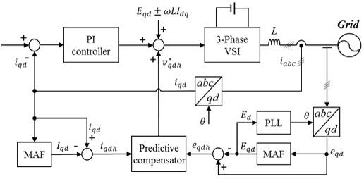
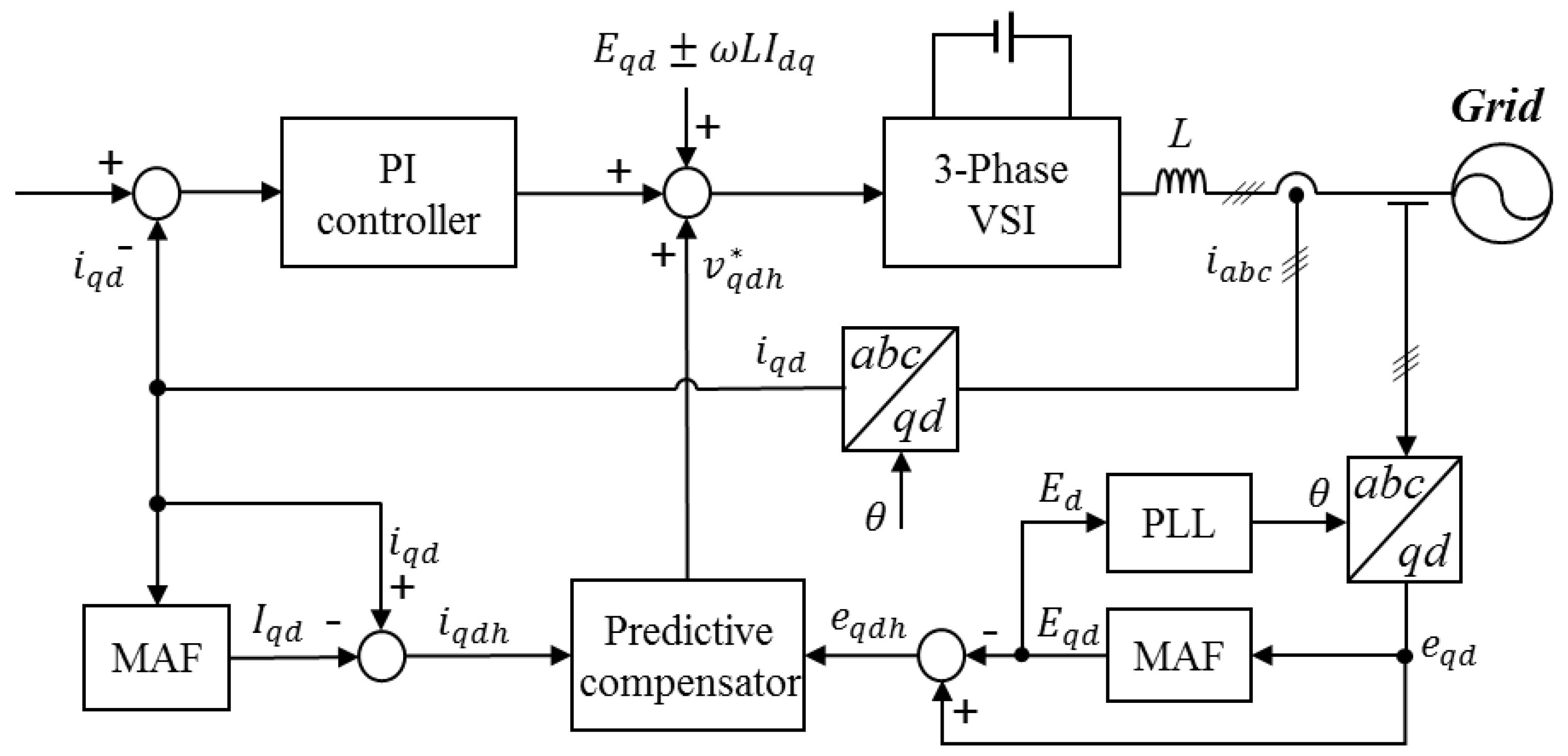
Figure 2 shows the control block diagram of the proposed control scheme in which the three-phase inverter is connected to the grid through
L filter. The overall system mainly consists of a three-phase inverter, a current controller, a predictive basis harmonic compensator, and MAFs, which are used for system model decomposition as well as performance improvement in PLL. The grid voltages and inverter currents are measured and then transferred into the variables on the synchronous reference frame using the Park’s transformation. The transformed grid voltages into the synchronous frame are first processed with the MAF to obtain pure DC-quantity without the harmonic distortion, and then, used in PLL algorithm to determine the angular displacement in grid voltage accurately. Similarly, the transformed currents into the synchronous frame are processed with the MAF to obtain DC-quantity. These voltages and currents in DC-quantity are subtracted from
and
to extract the harmonic components of
and
. The current controller is formed by combining a synchronous PI decoupling controller and a predictive controller, where the PI decoupling controller is employed to regulate the inverter currents to follow their references and referred as a main controller.
From the inverter voltage equations in Equations (1) and (2), the reference voltages are obtained from the PI decoupling controller as follows:
where the symbol “*” denotes the reference quantity and,
and
are the proportional and integral gains of the PI controller, respectively.
In the discrete-time domain, the reference voltages in Equations (12) and (13) can be expressed at each sampling instant
k as follows:
where
,
, and
Ts is the sampling period.
3.1. MAF and MAF-PLL
An MAF is employed as ideal LPF in the proposed control scheme, where the window length is chosen as one period of the fundamental grid voltage to retain the generality. However, the window length can be set to half of fundamental period in the case of the filtered variables are in the synchronous reference frame since the majority of the uncertainties in three-phase voltages are odd harmonics that become even harmonics in the synchronous reference frame.
The input–output relationship of the MAF can be described in continuous-time domain by
where
Tw is the window length,
is the output signal, and
is the input signal. The continuous-time transfer function of the MAF can be obtained from Equation (16) as
The transfer function in Equation (17) shows that the MAF only requires a time equal to its window length to reach the steady state. For a digital implementation, the transfer function of the MAF can be discretized from Equation (17) as
where
Tw =
NTs with
N equal to the number of samples in one window length (
N must be an integer). From Equation (18), it can be observed that the MAF provides an effective solution in view of the computational burden as compared with the BPF. Moreover, since the MAF only requires one period of fundamental grid voltage for the filter output to converge, the dynamic response of the MAF-based harmonic extractor is much faster than that of the BPF-based harmonic extractor, which requires almost six periods of fundamental grid voltage to reach steady-state condition [
16].
In practical implementation, the mismatch between the designed window length
Tw and the value of
NTs makes errors in amplitude and phase angle. This problem can be solved by using several proved techniques such as rounding of
Tw/
Ts to the nearest integer, weighted mean value approach [
20], and linear interpolation [
21]. In order to secure the calculating capability of main controller while retaining the errors within an acceptable value [
17], the rounding scheme that adjusts
Tw/
Ts to the nearest integer is used in this paper. Thus, the number of samples in one window length
N can be obtained as follows:
where “
” denotes the round function which returns the nearest integral value.
In the grid-connected inverter system, the inverter needs to monitor the angular displacement of the grid voltage in order to synchronize the inverter currents with the grid. Generally, the SRF-PLL, which is based on the Park’s transformation and a low bandwidth PI controller, is commonly employed in three-phase grid-tied inverter systems. Under the distorted grid voltages, however, the angular displacement of grid voltage cannot be tracked exactly due to the inability of the PI controller to reject sinusoidal disturbances. As a result, the detected angular frequency of grid contains high order harmonics, which cause an increase of harmonic contents in inverter currents. As is illustrated in
Figure 2, the filtered
d-axis voltage is fed directly to the conventional SRF-PLL instead of the measured
d-axis voltage.
The open loop transfer function of MAF-PLL can be obtained from Equation (17) and the conventional SRF-PLL as
where
and
are the proportional and integral gains of the PI controller in the conventional SRF-PLL, respectively. By using the first-order Padé approximation [
17], Equation (17) may be approximated as
Replacing
in Equation (20) by approximated term
in Equation (21), the transfer function in Equation (20) becomes
From Equation (22), the approximated closed-loop transfer function of MAF-PLL can be described as
By using the MAF, which acts as an ideal LPF, to obtain DC-quantity of the d-axis grid voltage, the grid angular displacement can be detected accurately even when the grid voltages are highly distorted. In addition to mathematical analyses, the simulation and experimental results of MAF-PLL will be given in the following sections to demonstrate the performance of the designed filter as well as its effect on inverter currents.
3.2. Predictive Harmonic Compensator
The harmonic compensator, which is based on the predictive control, is also illustrated in
Figure 2. The high frequency sinusoidal currents and voltages are extracted by means of the MAFs, and then, these values are used to form a predictive basis harmonic compensator. In the discrete-time domain, the harmonic voltage equations in Equations (10) and (11) can be described as
In Equations (24) and (25), by replacing the currents at sampling instant
) by the reference currents, the predictive control law to suppress the harmonic currents can be expressed as
where
and
denote the
q-axis and
d-axis harmonic reference currents, respectively. These values should be set to zeros in order to eliminate the harmonic components in inverter output current.
From Equations (14), (15), (26), and (27) with
, the
q-axis and
d-axis inverter reference voltages of the proposed control scheme are represented as
As a result of using the decomposition model, the predictive basis harmonic compensator only has to deal with the harmonics model. Therefore, the problems associated with the parameters mismatch and time delay in the predictive control are highly reduced.
4. Simulation Results
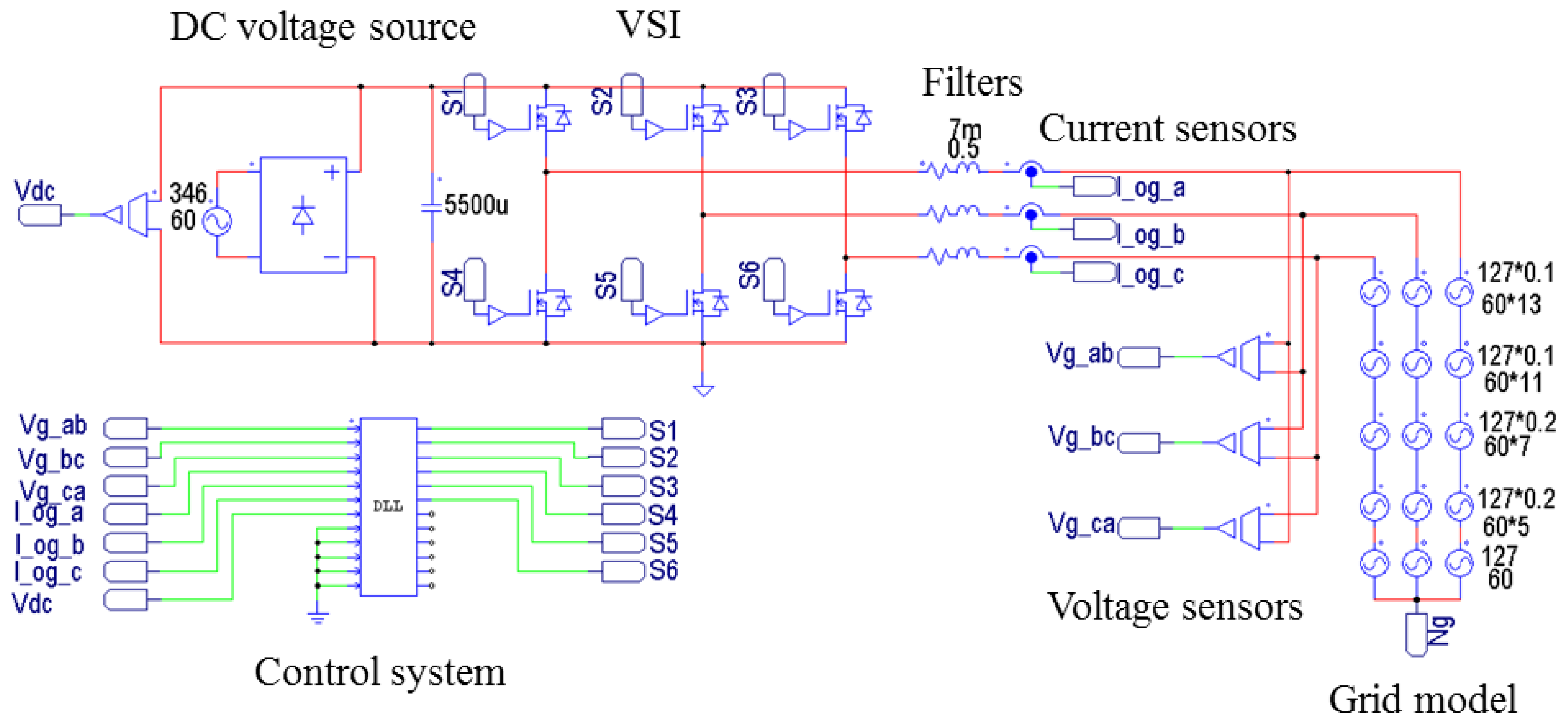
To evaluate the performance of the proposed control scheme, the simulations have been done for three-phase grid-connected inverter using the PSIM software.
Figure 3 shows the whole system configuration where the main controller is implemented with the PSIM dynamic link library (DLL) block. The system parameters are summarized in
Table 1.
In addition to ideal grid voltages, the distorted grid voltages are used in order to evaluate the control performance in adverse operating conditions of the grid. For a distorted condition of grid voltage, the 5th and 7th harmonics with 20% of the fundamental component and the 11th and 13th harmonics with 10% of the fundamental component are added to the ideal grid voltages. The resultant three-phase grid voltages are shown in
Figure 4, where the THD is 31.7%. In this figure,
,
, and
denote three-phase grid voltages.
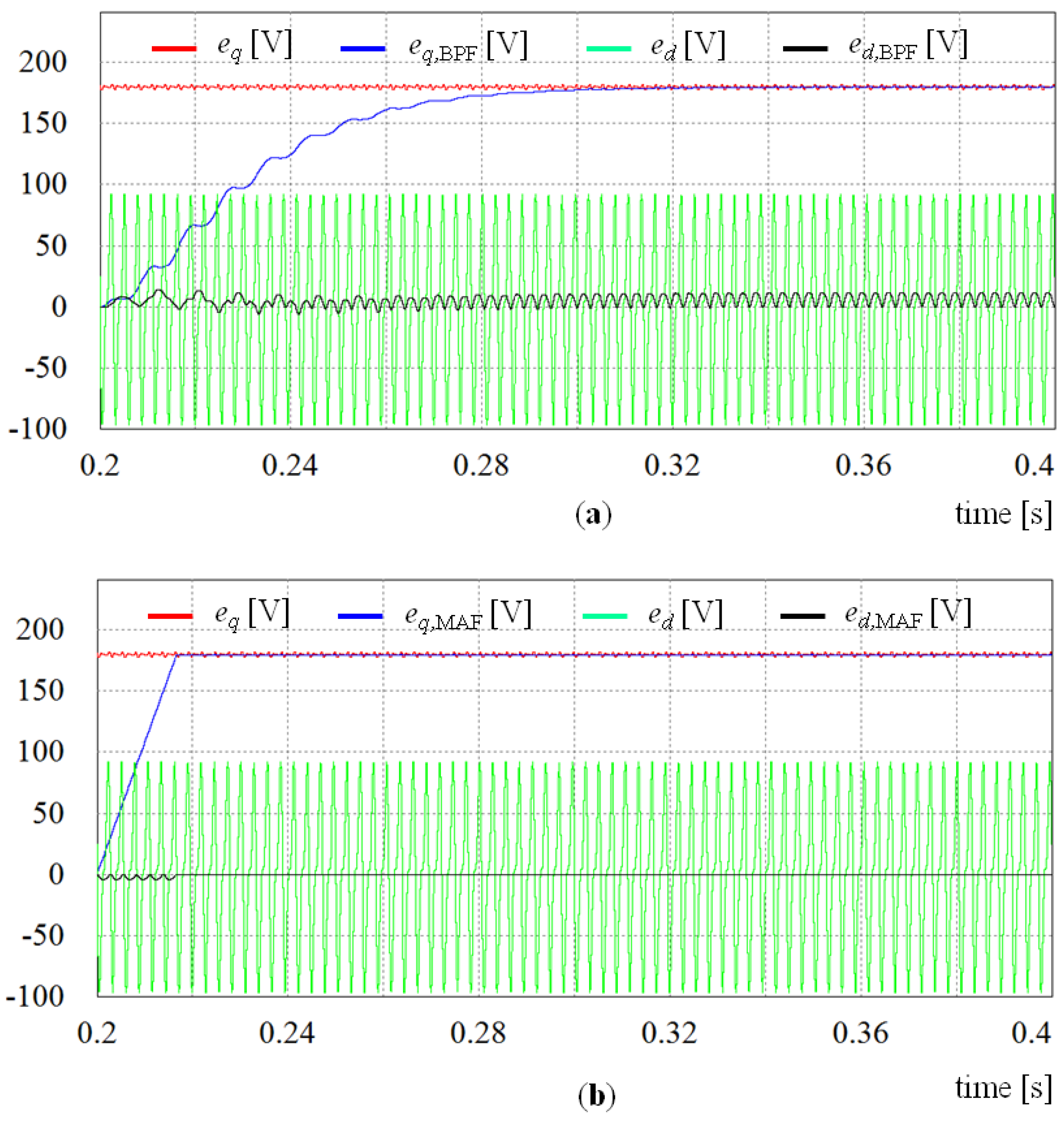
Figure 5 shows the performance comparison of dynamic responses between the BPF and MAF under the distorted grid voltages. As a result of harmonic distortion in grid voltages as shown in
Figure 4, the
q-axis and
d-axis grid voltages
and
at the synchronous reference frame contain the harmonic components as well as DC-quantity. In
Figure 5,
and
denote the filtered outputs processed with the BPF, respectively. On the other hand,
and
denote the filtered outputs processed with the MAF, respectively. It is easy to notice that the transient responses of the MAF are nearly five times faster than those of the BPF in extraction of DC-quantity, since the MAF only requires one window length to reach its steady state. Furthermore, by selecting the number of samples
N to the nearest integer, the steady-state errors of the MAF can be lower than those of the fourth-order BPF (See the
d-axis values).
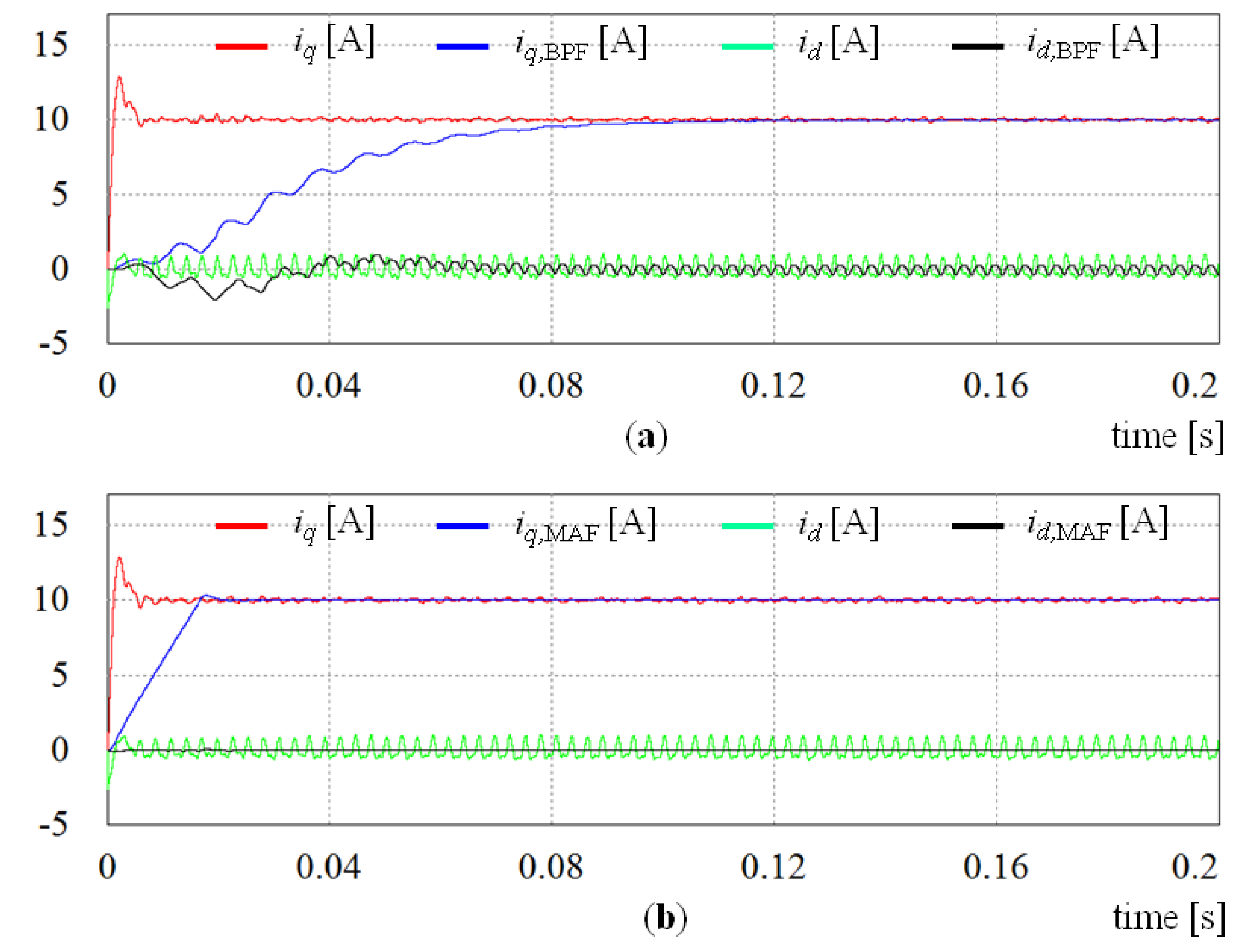
Similarly,
Figure 6 shows the comparison of dynamic responses to extracts DC-quantity between the BPF and MAF when the input signals are inverter currents. It is obvious that the transient response and steady-state error are much more improved by adopting the MAF, which results in the improvement of harmonic extraction.
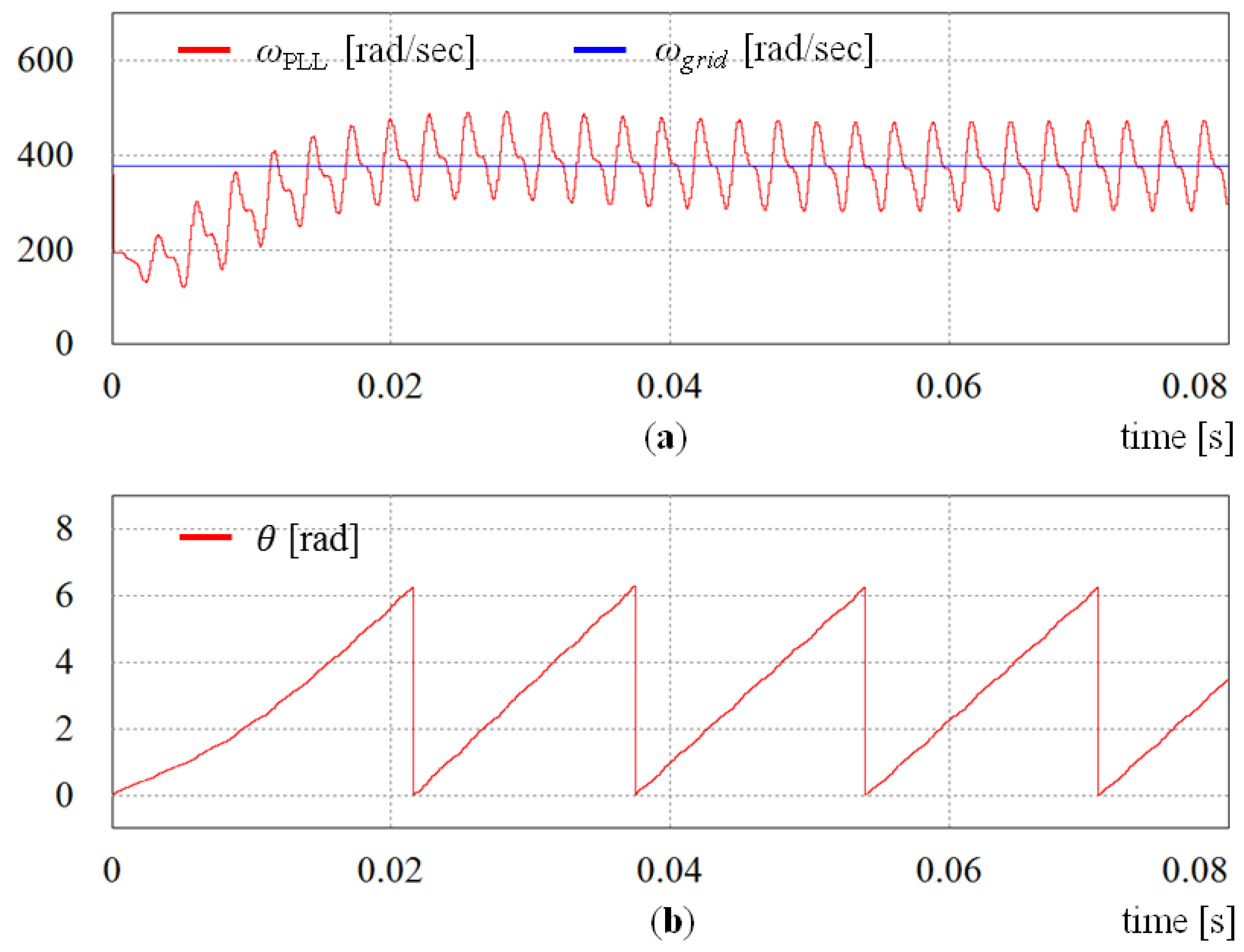
As stated earlier, the obtained angular displacement and angular frequency from the conventional SRF-PLL are severely distorted under the distorted grid voltages because of the inability of the PI controller to reject high frequency disturbances.
Figure 7 shows the waveforms for the angular frequency
and angular displacement θ determined by the conventional SRF-PLL. It is easy to notice that the angular frequency fluctuates around the fundamental value
. Also, this fluctuation makes the obtained angular displacement θ distorted as is shown in
Figure 7b. On the contrary,
Figure 8 shows the simulation results for the MAF-PLL scheme under the distorted grid voltages. It can be clearly observed that the dynamic response of the MAF-PLL is comparable to that achieved by the SRF-PLL. The MAF-PLL, however, provides attractive steady-state response as a result of an excellent filtering capability of the MAF.
To highlight the effectiveness of the proposed control scheme, the comparative simulation results with the conventional control scheme for a grid-connected inverter are also presented. The conventional control scheme comprises a synchronous PI decoupling current controller and a SRF-PLL. In order to point out the weakness of the conventional control scheme, the simulation results both under the ideal and distorted grid voltages are shown in
Figure 9 and
Figure 10, in which
,
, and
denote three-phase inverter currents. As can be observed from the output current waveforms in
Figure 9, the conventional control scheme shows a good steady-state performance under the ideal grid voltages. In the abnormal grid conditions, however, the output current waveforms, illustrated in
Figure 10, are highly distorted due to the poor sinusoidal disturbance rejection capability of the PI controller both in current controller and in PLL.
In addition to the results obtained using the conventional PI control scheme, the simulations have been carried out for another harmonic compensation approaches for comparison.
Figure 11 shows the steady-state responses of the inverter currents using PR controller with different distorted grid conditions. To eliminate harmonic contents in inverter currents, only the resonant terms to compensate the 5th and 7th harmonics are added together with the fundamental controller. As shown in
Figure 11a, the compensation works well when the grid disturbance only contains 5th and 7th harmonics. However, when the grid has the harmonic disturbance in other frequencies, the control performance of this scheme is degraded dramatically.
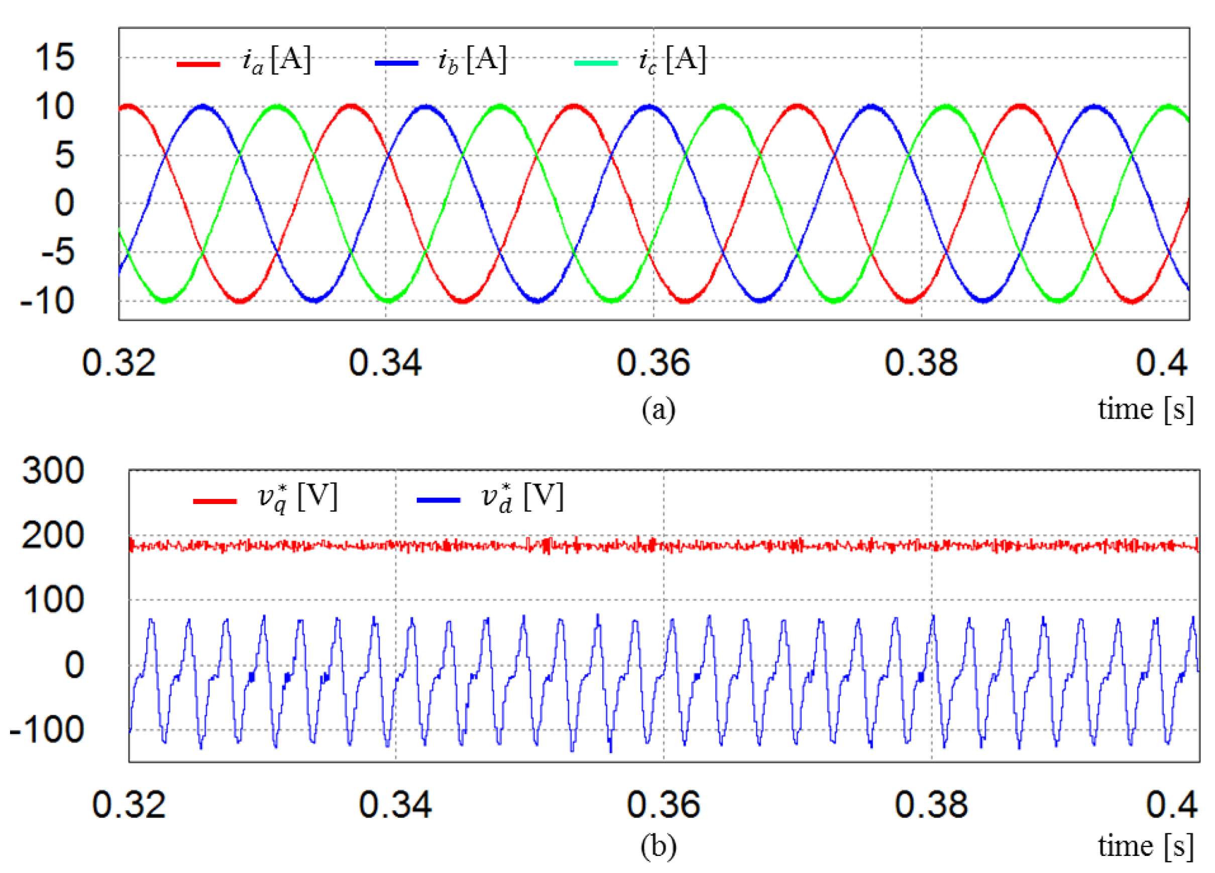
Another widely used compensation approach that employs nonlinear controller is the sliding mode control. As an illustration,
Figure 12 shows the control performance under distorted grid conditions when the sliding mode control is employed for harmonic compensation. As stated earlier, this control scheme can guarantee a good steady-state performance of target system, as shown in
Figure 12a. However, the chattering in control input signals is unavoidable as is observed in the waveforms of inverter reference voltages
and
in
Figure 12b. Moreover, it is not easy to meet the trade-off between the transient responses and steady-state performance in designing the sliding mode controller.
Figure 13 shows the simulation results of the proposed control scheme under the same distorted grid voltages as
Figure 10. In contrast to those in
Figure 10, the phase current waveforms in
Figure 13a still remain sinusoidal. Also, as can be observed in the
q-axis and
d-axis current waveforms in
Figure 13b, the proposed control scheme gives nearly constant currents, which imply that phase currents have relatively low harmonic contents.
Despite the fact that the harmful disturbances in three-phase grid are mainly sinusoidal harmonics, any type of disturbance may occur in gird in extreme cases.
Figure 14 shows the comparative current responses in the presence of random disturbances in three-phase grid voltages. Random values are generated as shown in
Figure 14c and these values are added with grid voltages to generate random disturbances in three-phase. From the comparative simulation results between the proposed control scheme in
Figure 14a and the conventional PI control scheme in
Figure 14b, it is verified that the proposed control scheme is robust against even random disturbance in grid voltage.
Although low harmonic contents in inverter currents at steady state can be achieved even under the distorted grid voltages by using the proposed control scheme, the transient response of the proposed control scheme becomes worse than that of the conventional control scheme. The degradation in transient response is mainly caused by the phase delay of filters used for the harmonic extractor.
Figure 15 shows the transient responses of the conventional control scheme, in which
Figure 15a shows the waveforms of phase currents and
Figure 15b shows the waveforms of the
q-axis and
d-axis currents with the
q-aixs current reference
. As can be observed form
Figure 15b, the conventional scheme responds rapidly to the change of reference currents. However, as is seen in
Figure 16, the transient response of the proposed control scheme is relatively slow due to the delay introduced by the harmonic extractors. The transient response in
Figure 16b is almost ten times slower than that of the conventional control scheme. This result is unacceptable to be used for a current control loop in DG systems because they are supposed to provide very fast response.
Even though the major advantage of using the MAF in the harmonic extractor over BPF or LPF is that the transient period introduced by filter is well reduced and predictable, this delay by the MAF should be compensated further in order to improve the transient performance of current controller. A compensation method for phase delay has been proposed in [
18]. Although this method reduces the transient response of the MAF, the steady-state error is noticeably increased. By considering that the reference currents are generally obtained from the voltage control loop or droop control loop in grid-connected inverter systems, it is always possible to detect the change in reference currents. Based on this information, to improve the transient response of current control loop, the
q-axis and
d-axis harmonic currents
and
are temporally replaced during the transient period of the MAF with
where
and
are the approximated
q-axis and
d-axis harmonic currents based on the assumption that the fundamental currents can reach theirs reference values instantly.
Figure 17 shows the simulation results of the proposed control scheme with temporary replacement of the harmonic currents during the transient period of the MAF, which is one window length. In order to show the transient response of the proposed control scheme, the
q-axis reference current is increased from 5 A to 10 A at
t = 0.2 s, and then, decreased to 7 A at
t = 0.3 s. As is clearly observed in
Figure 17b, the
q-axis current can reach its reference value immediately, while retaining good harmonic suppression characteristics in phase currents. Although the replacement of the harmonic currents during transient period of the MAF may increase harmonic contents in inverter current, the transient performance can be considerably improved. Moreover, the increase of the harmonic components in inverter currents can be negligible because it lasts during only one window length of the MAF.
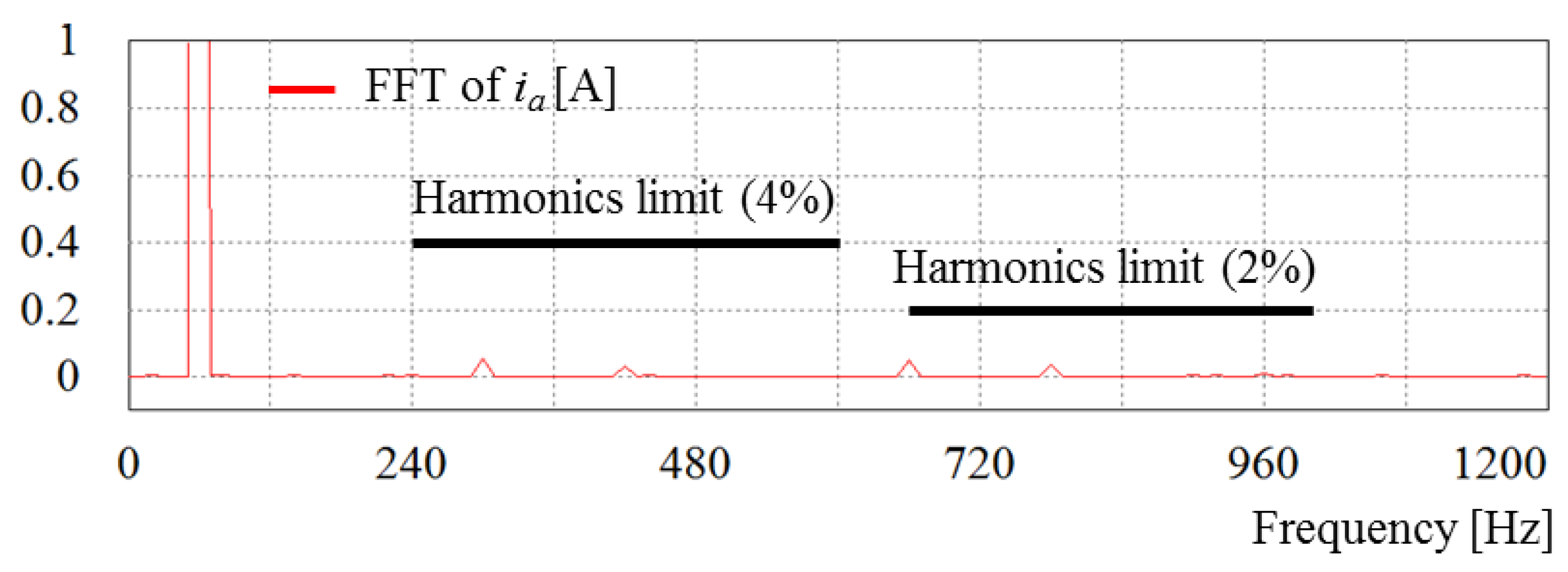
Figure 18 shows the fast Fourier transform (FFT) result of
a-phase current using the proposed control scheme under the distorted grid voltages, in which the harmonic limits according to the IEEE 1547 interconnection of distributed generation regulations are also indicated for comparison. As can be seen, the 5th and 7th harmonics are significantly reduced and all the harmonic components are within the limits.
5. Experimental Results
The proposed control scheme has been implemented in a 2 kVA three-phase grid-connected inverter system as shown in
Figure 19. The whole control algorithms are implemented using 32-bit floating-point DSP TMS320F28335 with clock frequency of 150 MHz [
22]. The sampling period is set to 100 µs in the experiments, which yields the switching frequency of 10 kHz. The intelligent power module (IPM) is employed for three-phase grid-connected inverter. The inverter phase currents are detected by the Hall-effect devices and are converted through internal 12-bit A/D converters. The inverter reference voltages are applied using the symmetrical space vector PWM method. The parameters of the experimental system are summarized in
Table 1. For distorted condition of the grid voltages, 10% of the fifth and the seventh harmonics, respectively, and 1% of the eleventh and the thirteenth harmonics, respectively, are injected to the grid voltage, which results in the THD of 14.2%.
Figure 20 shows the experimental results for the SRF-PLL and MAF-PLL algorithms under the distorted grid voltages for comparison. As can been seen, the angular frequency waveform obtained by the SRF-PLL algorithm is highly distorted due to the existence of high frequency disturbances in three-phase grid voltages. In contrast, the angular frequency obtained from the MAF-PLL algorithm remains nearly constant in the steady-state even when the grid voltages are highly distorted. As a result, the angular displacement is not influenced by the distorted grid voltages, which proves the effectiveness and robustness of the MAF-PLL.
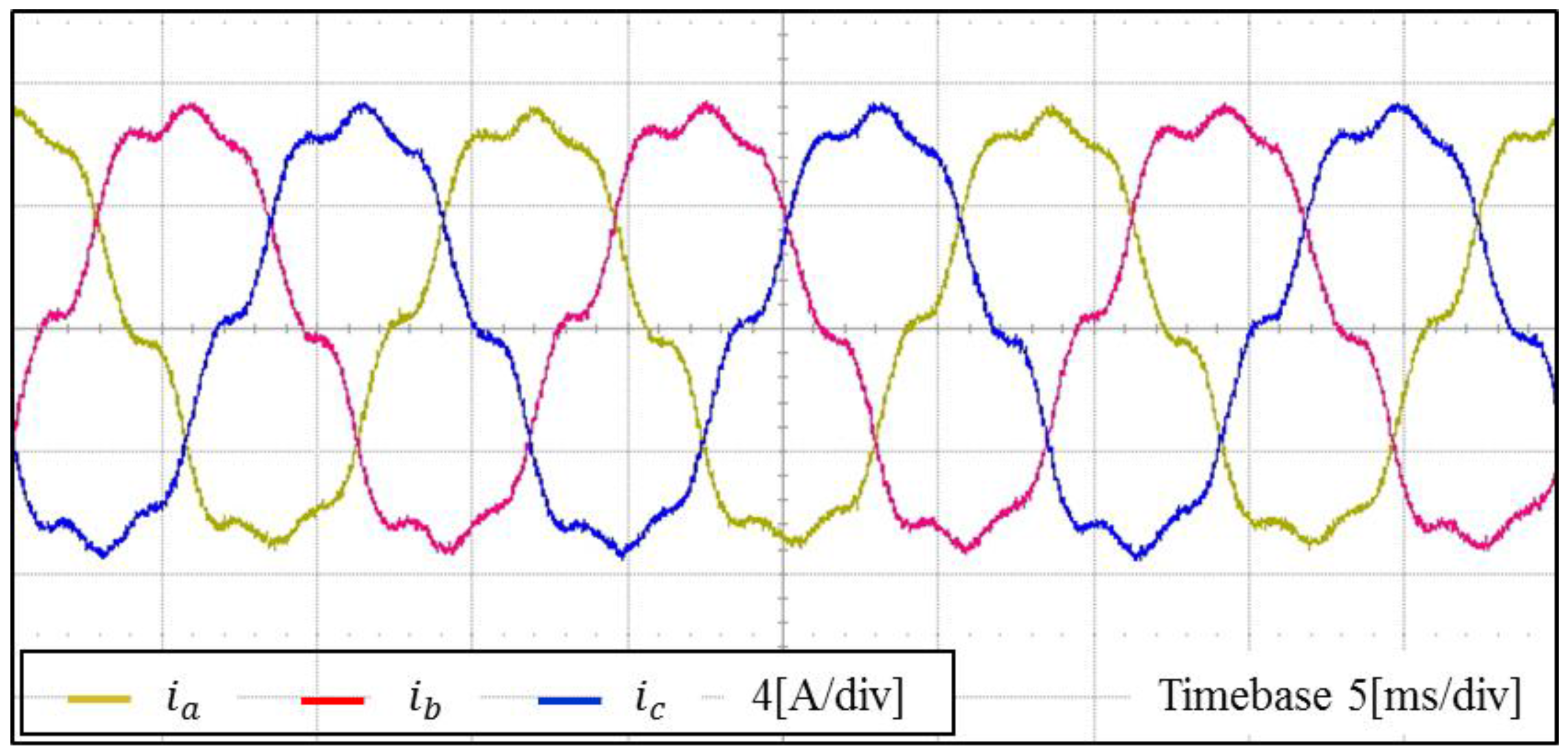
Figure 21 shows the experimental results for inverter output currents when the conventional synchronous PI decoupling controller and SRF-PLL algorithm are employed under the distorted grid voltages. It is clearly observed in this figure that phase current waveforms are quite non-sinusoidal. This indicates that the conventional control scheme fails to meet the high power quality in a real system where there exist sinusoidal disturbances.
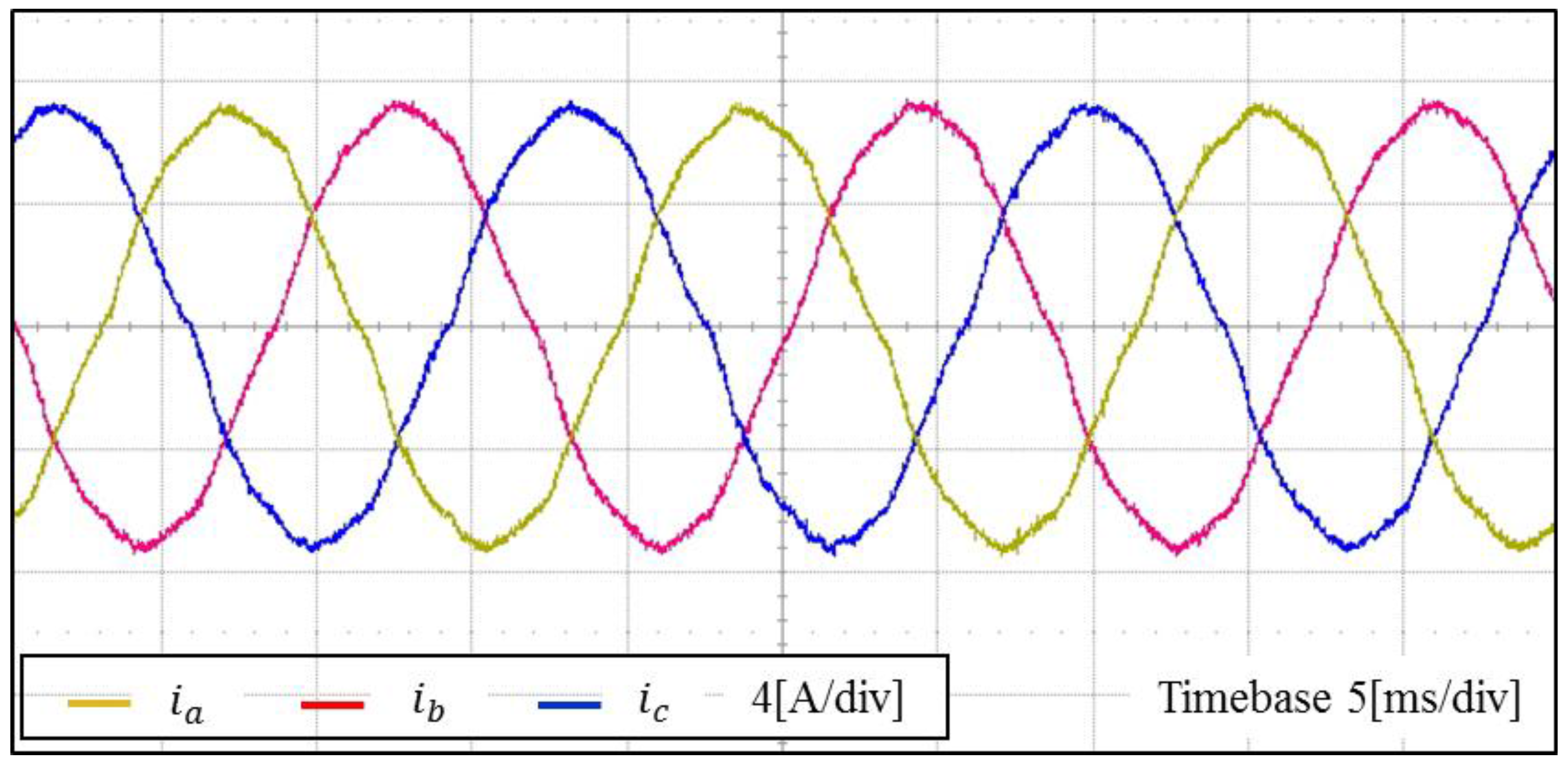
Figure 22 shows the experimental results for inverter output currents using the proposed control scheme under the same conditions as
Figure 21. Due to an effective compensating capability of the proposed control scheme, the inverter phase currents shows considerably sinusoidal waveforms regardless of the high distortion level in the grid voltages.
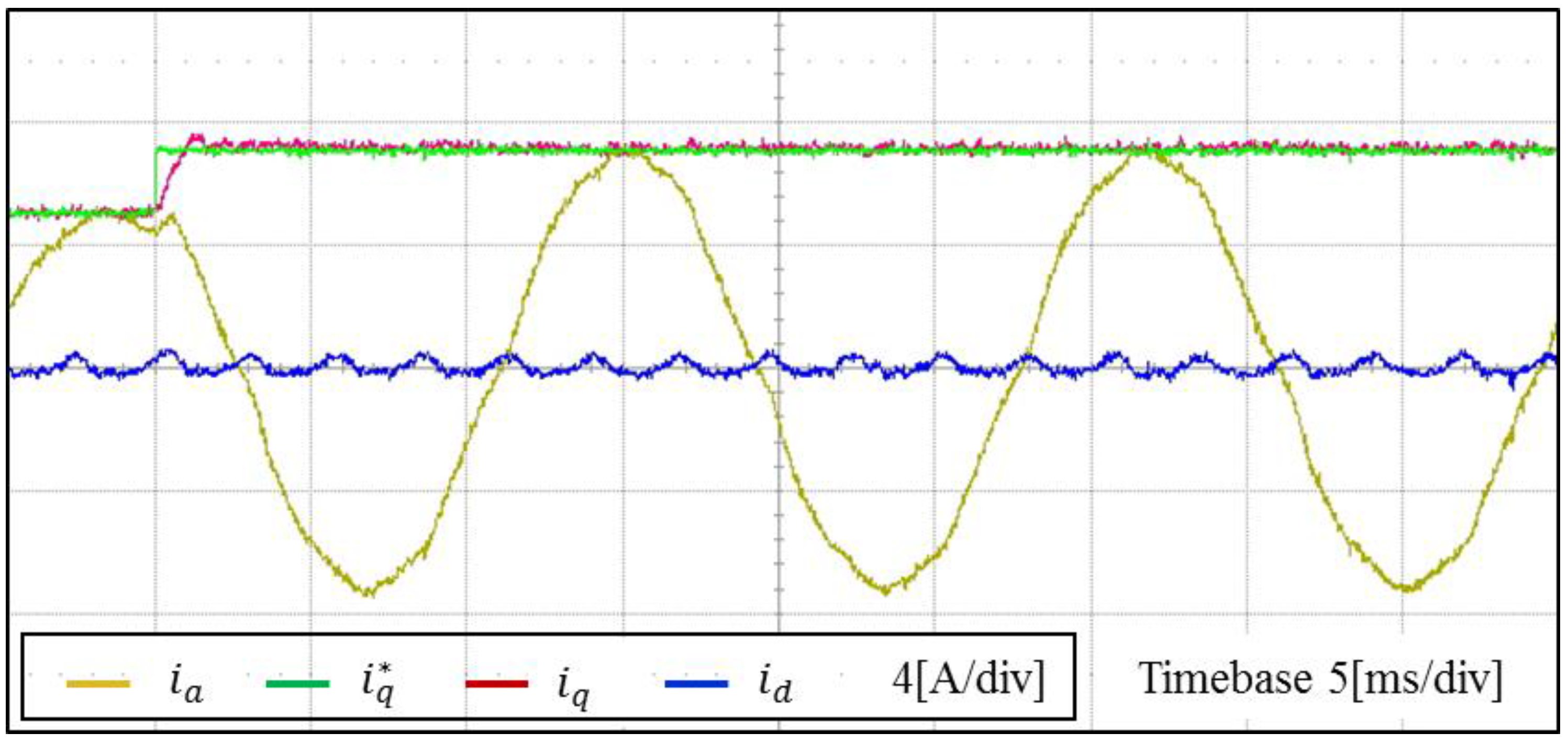
As mentioned previously in
Figure 16, the delay of the MAF might slow down the dynamic response in inverter currents. In order to get rid of this problem, a modification technique that replaces the harmonic current with temporary values has been used. The transient current response of the proposed control scheme under the step change in the current reference is demonstrated in
Figure 23. As is shown, the
q-axis inverter current instantly reaches its new reference value, which validates the fast dynamic response of the proposed control scheme.
Figure 24 shows the experimental FFT result of
a-phase inverter current using the proposed control scheme under the distorted grid voltages. It is clearly observed that the low-order harmonic components in the fifth, seventh, eleventh, and thirteenth order are considerably reduced. Furthermore, all the harmonic components well satisfy the harmonic limits of IEEE std. 1547 [
6].
As a result, the proposed control scheme has a good disturbance rejection capability in steady state as well as fast dynamic response.


