Article

Power Quality Improvement and LVRT Capability Enhancement of Wind Farms by Means of an Inductive Filtering Method

1
College of Electrical and Information Engineering, Hunan University, Changsha 410082, China
2
Hunan Electrical Power Corporation Economical & Technical Research, Changsha 410004, China
3
Department of Electrical Engineering, Wroclaw University of Technology, Wroclaw 50370, Poland
*
Author to whom correspondence should be addressed.
Energies 2016, 9(4), 302; https://doi.org/10.3390/en9040302
Submission received: 27 February 2016 / Revised: 31 March 2016 / Accepted: 13 April 2016 / Published: 20 April 2016

Abstract

:
Unlike the traditional method for power quality improvement and low-voltage ride through (LVRT) capability enhancement of wind farms, this paper proposes a new wind power integrated system by means of an inductive filtering method, especially if it contains a grid-connected transformer, a static synchronous compensator (STATCOM) and fully-tuned (FT) branches. First, the main circuit topology of the new wind power integrated system is presented. Then, the mathematical model is established to reveal the mechanism of harmonic suppression and the reactive compensation of the proposed wind power integrated system, and then the realization conditions of the inductive filtering method is obtained. Further, the control strategy of STATCOM is introduced. Based on the measured data for a real wind farm, the simulation studies are carried out to illustrate the performance of the proposed new wind power integrated system. The results indicate that the new system can not only enhance the LVRT capability of wind farms, but also prevent harmonic components flowing into the primary (grid) winding of the grid-connected transformer. Moreover, since the new method can compensate for reactive power in a wind farm, the power factor at the grid side can be improved effectively.

1. Introduction

In recent years, wind power generation has become a very attractive source of renewable energy thanks to its unique merits: it is economical, clean and inexhaustible. Thus, more and more wind farms are being connected to power systems [1,2]. However, such large-scale integration of wind power into the power system brings technical challenges for the wind farm operators; for example, the wind turbines should keep continued connection with the power system during a fault and other conditions [3,4]. Moreover, it is important for wind farms to improve power quality [5,6,7,8,9,10]. For modern wind farms, variable speed wind turbines, such as double-fed induction generator (DFIG) and permanent magnet synchronous generator (PMSG), are the commonly installed turbine types. It is worth noting that the modern wind turbines are based on the voltage source converters (VSCs), which consist of power electronics device and employ a carrier-based pulse width modulation (PWM) technique. The harmonic components are inevitably generated by VSCs. Furthermore, the imperfections in control system of wind turbines and the nonlinearities in generators and transformers also produce harmonic components, polluting the public network. Particularly, the harmonic components freely flow into the grid-connected transformer, which inevitably leads to a series of problems, such as harmonic loss, vibration and noise. Another concern of grid-integrated wind power system is the output voltage fluctuation resulting from the wind speed fluctuation. Voltage fluctuation may cause serious problems for electric devices requiring a high-quality voltage supply. Therefore, the main purpose of the normal operation requirement for wind farms is to maintain voltage stability and provide high power quality.
Moreover, many grid codes in several countries require wind turbines to remain connected to the power system under fault conditions, in order to restore the system to the normal conditions as quickly as possible. Such requirements are known as fault ride through (FRT) or low-voltage ride through (LVRT) capability of wind turbines. For example, the grid code ENTSO-E is recommended as a common frame for all European countries [11]. Figure 1 shows the ENTSO-E LVRT requirement for grid-connection, where the wind farms are expected to stay connected even when the grid voltage drops down to 0. In summary, the harmonic components, the voltage fluctuation and the LVRT capability are the crucial issues and should be carefully addressed to improve the power quality and increase the operating efficiency of wind farms [12,13,14,15].
Generally, in order to improve the power quality, wind farms mainly adopt the passive power filtering (PPF) method to suppress the harmonic currents and compensate for reactive power. The passive power filters are configured at the wind farm side of the grid-connected transformer [16]. However, its filtering performance is easily affected by its own parameters change. In addition, the passive filter usually adopts a detuned design in order to avoid the potential series/parallel resonance with the system impedance, meaning that the filtering performance is reduced to a certain degree. Since the PPF method cannot provide a good power factor over the large wind power range, the reactive compensation devices are usually applied at the wind farm side of the grid-connected transformer, such as the static VAR compensator (SVC) and the static synchronous compensator (STATCOM) [17]. The LVRT capability of wind farms can be improved by injecting or absorbing the reactive power from SVC. However, SVC generates harmonic currents, which is not good for the public network [18]. Compared to SVC, STATCOM has better performance at the reactive compensation and improving LVRT capability of wind farms. It should be noted that the STATCOM usually adopts a coupling transformer to interface with grid, which increases the cost of investment.
In order to satisfy the multiple purposes of suppressing harmonic currents, compensating reactive power and improving the LVRT capability, this paper proposes a new wind power integrated system by means of the combination of the inductive filtering method and a STATCOM. The inductive filtering method was first proposed in [19] for the high-voltage DC (HVDC) system, and [20,21] showed the outstanding performance on harmonic suppression and reactive power compensation, respectively. The proposed wind power integrated system fully utilizes the filtering and reactive compensation ability of the new grid-connected transformer with fully-tuned (FT) branches and STATCOM, aiming at the power quality improvement and LVRT capability enhancement of wind farms. This paper significantly develops initial ideas presented in [22].
The structure of this paper is organized as follows. Section 2 presents the main circuit topology of the new wind power integrated system and describes its technical features. Section 3 establishes the equivalent circuit model of the new wind power integrated system, and then the corresponding mathematical model is established to reveal the operation of the inductive filtering method. Section 4 shows the properties of the new wind power integrated system related to reactive power compensation. In Section 5, the transient simulation of the new wind power integrated system is carried out to validate the theoretical analysis. Finally, the conclusions are given in Section 6.

2. Main Circuit Topology of the New Wind Power Integrated System

2.1. Topology

Figure 2 shows the main circuit topology of the proposed wind farm integrated system. The wind farm is composed of 25 PMSGs with a rating of 2 MW each, with the total installed capacity of 50 MW. Each wind turbine is connected in parallel to the 35 kV bus via a 2.2 MVA, 0.69/35 kV transformer and then connected to the public network by means of a new grid-connected transformer. The new transformer has the grid-, the load- and the filtering-winding. The wiring scheme of the new grid-connected transformer is shown in Figure 3. As with the description in [19], in order to implementing inductive filtering method, the compensation devices, which consist of the inductive filtering device and a cascade multiple STATCOM with ±10 Mvar rating, should be connected to the filtering-winding of the new grid-connected transformer. In this way, the coupling transformer can be saved. Moreover, the STATCOM consists of the six H-bridges, these modules being connected in cascade in each phase. It is worth noting that this proposed wind power integrated system can suppress the harmonic components whatever they come from the public network or the wind farm, because the inductive filtering devices have the natural ability of suppressing harmonic components coming from both directions. Further, the STATCOM and FT branches can also compensate for the reactive power for the wind farm, especially the STATCOM, which can compensate for the dynamic voltage changes of the wind farm by means of injecting or absorbing reactive power.

2.2. Wind Turbine Modeling

The primary important component in the modeling of PMSG is the wind turbine model, which can transform wind energy to the power Pmech, expressed by [23,24,25],
P m e c h = 1 2 ρ π R 2 C p ( λ , β ) ω 3
where ρ is the air density; ω is the wind speed; R is the rotor radius; and Cp (λ, β) is the power coefficient, depending on the blade angle β and the tip speed ratio λ.
The tip speed ratio can be described by
λ = ω R R ω
where ωR is the rotor speed.
For each blade angle β, there is an optimal tip speed ratio λopt and a corresponding optimal Cp value that is an optimal Cpopt with the maximal power capture from the wind. Then, the power coefficient is obtained as
C p ( λ , β ) = 0.5176 ( 116 λ i 0.4 β 5 ) e 21 λ i + 0.0068 λ
1 λ i = 1 λ + 0.08 β 0.035 β 3 + 1
According to Equations (3) and (4), the Cp-λ curves for different blade angles are obtained as shown in Figure 4.

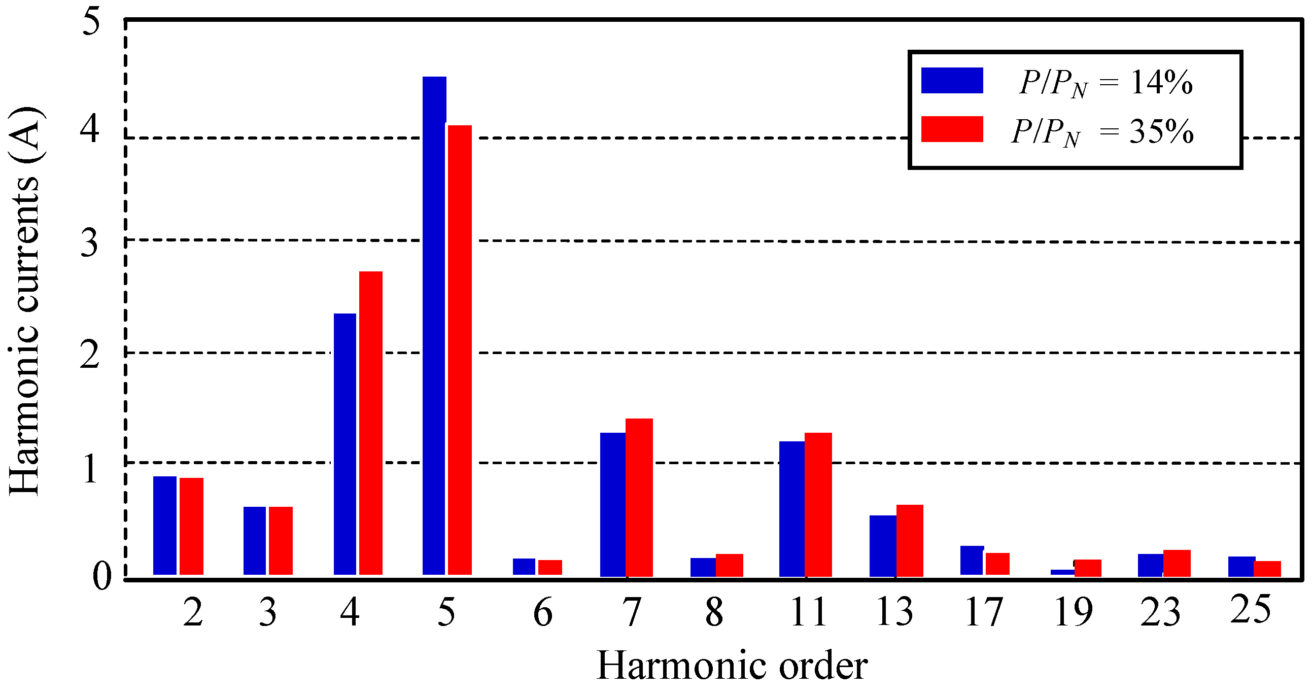
2.3. Harmonic Currents Produced by a Wind Farm

It can be seen from Figure 2 that the PMSG contains the machine-side converter (MSC) and the grid-side converter (GSC). The GSC operates at the grid frequency 50 Hz and is responsible for regulating the DC bus voltage and can also be used to generate or absorb reactive power. However, the MSC operates at a much lower frequency and is responsible for regulating the active and the reactive power of the generator. Due to the MSC not being directly connected to the grid, the harmonic currents generated by MSC cannot transfer to the grid but to the generator. Both the MSC and the GSC adopt the PWM techniques for insulated gate bipolar transistor (IGBT) control [26,27].
When the PMSG operates at the normal conditions, the output harmonic characteristic of the two converters is influenced by the following factors: the carrier frequency fs, the modulation ratio ma, and other factors. Generally, the harmonic orders n produced by these two converters can be determined by [9]:
n = k 1 × m a ± k 2
where k1 = 1, 2, 3, etc.; and k2 = 1, 2, 3, etc. Note that k1 and k2 cannot be simultaneously equal to even or odd numbers.
Generally, the modulation ratio ma is large, thus, we can see from Equation (5) that the output harmonic currents of these two converters have less low-order, but high levels of high-order harmonic currents can be generated. As mentioned in the above analysis, only the harmonic currents produced by the GSC can transfer to the grid. In fact, in the real-world wind farm, the values of the high-order harmonic currents is low whereas 4th, 5th, 7th and 11th have the high magnitudes, as shown in Figure 5. These data are measured in a real 50 MW wind farm with PMSGs, which operates with two different wind power ratios. This real wind farm is called the Baolian wind farm, located in the city of Shaoyang in the Hunan Province in China. The geographical information of the wind farm is shown in Figure 6. Actually, these harmonic currents are generated due to the non-ideal operation of the PWM technique and also due to the control interaction of PMSGs with the public network [27]. In this paper, the inductive filtering method is proposed to suppress these low orders harmonic currents, and the design parameters for the wind farm with the inductive filtering method is discussed in Section 4.

3. Theoretical Analysis

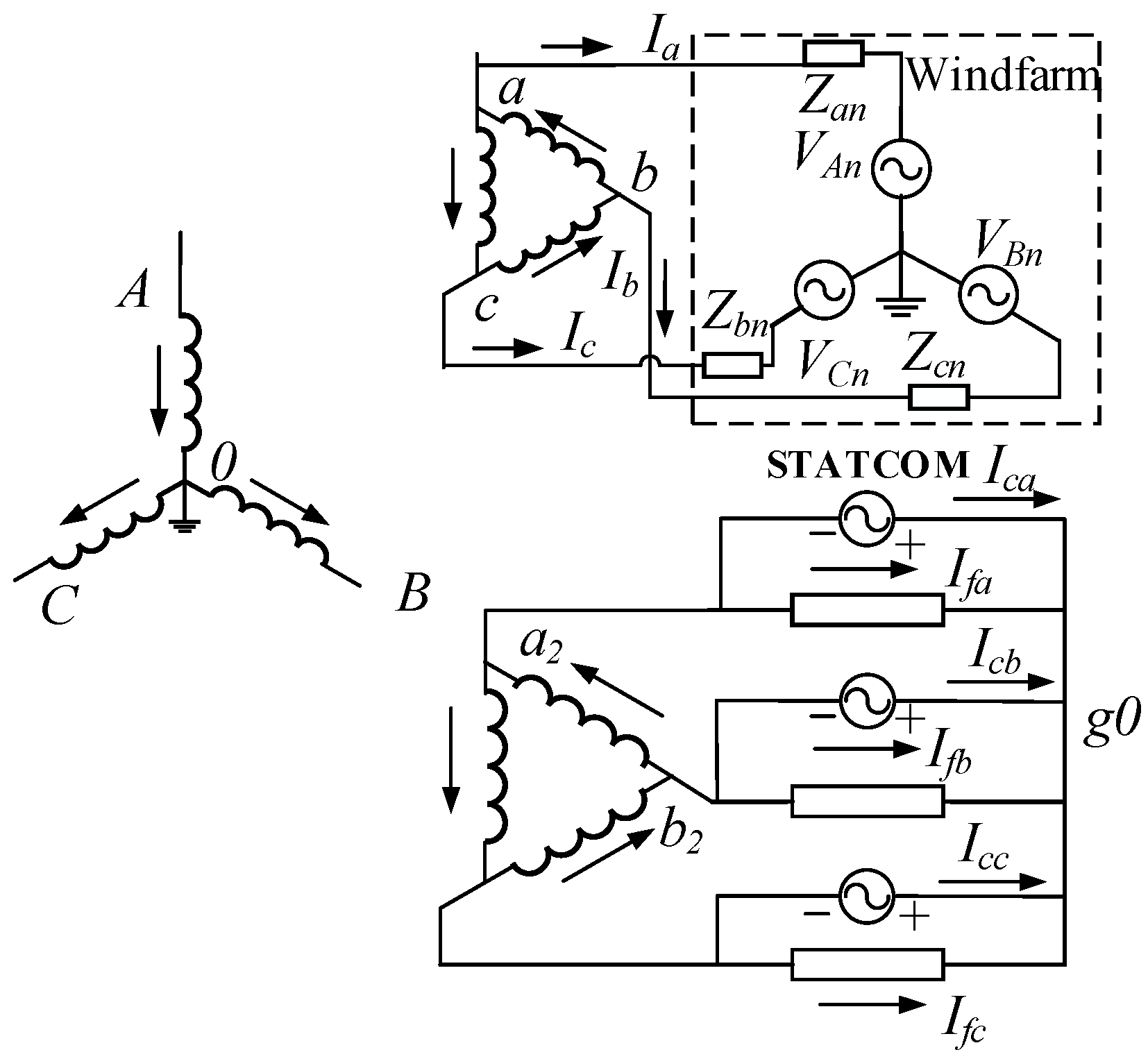
3.1. Harmonic Model and Equivalent Circuit Model

Figure 7 shows the single-phase equivalent circuit model of the new grid-connected transformer with FT branches and STATCOM, where the VSC-based wind turbine generators are regarded as the voltage source. According to the flow path of the n-order harmonic current shown in Figure 7, the following equations can be obtained:
{ I S n = I 1 n I 3 n = I f n I S T n I 2 n = I n
where I1n, I2n and I3n are the harmonic currents in the grid-, the load- (wind farm side) and the filtering-winding of the new grid-connected transformer, respectively; additionally, ISn, In, Ifn and ISTn are the n-order harmonic currents at the grid side, the load side, the FT branches side and the STATCOM side, respectively. Note that the STATCOM cannot compensate for the harmonic currents, i.e., ISTn = 0.
Similarly, we can obtain the voltage equations at the n-order harmonic frequency, i.e.,
{ V 1 n = V S n Z S n I S n V 3 n = V f n V f n = Z f n I f n
where V1n and V3n are the harmonic voltage in the grid- and the filtering-winding of the new grid-connected transformer, respectively; Vfn is the harmonic voltage of the FT branches; VSn is the harmonic voltage at the grid side.
Moreover, the magnetic-potential balance equation of the new transformer can be expressed as follows:
N 1 I 1 n + N 2 I 2 n + N 3 I 3 n = 0
where N1, N2, N3 are the numbers of turns of the grid-, the load- and the filtering-winding, respectively.
Then, according to the theory of the multi-winding transformer and combining the equivalent circuit model shown in Figure 7, the voltage transfer equations can be obtained as follows [28]:
{ V 2 n N 2 N 1 V 1 n = N 1 N 2 Z 21 n I 1 n N 3 N 2 Z 2 n I 3 n V 2 n N 2 N 3 V 3 n = N 3 N 2 Z 23 n I 3 n N 1 N 2 Z 2 n I 1 n
The harmonic equivalent impedance of the grid-, load-, and filtering-winding of the new grid-connected transformer can be expressed as
{ Z 1 n = 1 2 ( Z 21 n + Z 13 n Z 23 n ) Z 2 n = 1 2 ( Z 21 n + Z 23 n Z 13 n ) Z 3 n = 1 2 ( Z 31 n + Z 32 n Z 12 n )
where Z12n, Z13n and Z23n are the short-circuit impedance between the grid- and load-winding, between grid- and filtering-winding, between load- and filtering-winding of the new grid-connected transformer, respectively. They can be obtained by the transformer short-circuit test.
According to the model, the current in the grid-winding of the new grid-connected transformer can be expressed as follows:
I S n = N 1 N 2 ( Z 3 n + Z f n ) N 1 2 ( Z 3 n + Z f n ) + N 3 2 ( Z 1 n Z S n ) I n N 3 2 V S n N 1 2 ( Z 3 n + Z f n ) + N 3 2 ( Z 1 n Z S n )
Assuming that there is no or little harmonic voltage in the public network, that is to say, VSn ≈ 0, the above Equation (11) can be rewritten as
I S n = N 1 N 2 ( Z 3 n + Z f n ) N 1 2 ( Z 3 n + Z f n ) + N 3 2 ( Z 1 n Z S n ) I n
From Equation (12), it can be seen that as long as the Z3n and Zfn are approximately equal to 0, the source harmonic current ISn is approximately equal to 0, which means there will be no induction harmonic current in the grid-winding of the grid-connected transformer. Therefore, in order to implementing inductive filtering method, there are two conditions must be realized: one is the impedance of FT branches should be 0 at the resonant frequency, and the other is the impedance of filtering-winding of new grid-connected transformer also should be 0. The designed method for implementing inductive filtering method is given in Section 4.1.

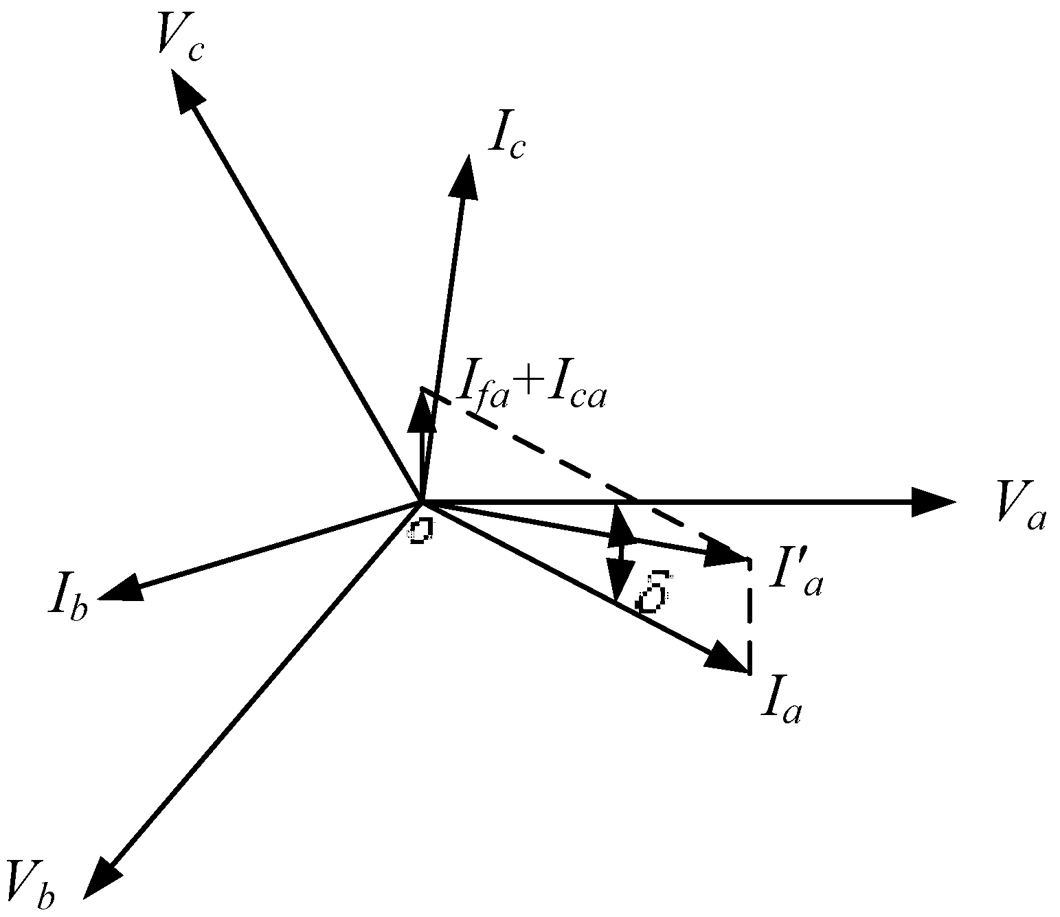
3.2. Reactive Power Compensation Characteristics

In the wind power integrated system, the FT branches and STATCOM can compensate for the reactive power that the wind farm needs. The current distribution in the new grid-connected transformer is shown in Figure 8. Correspondingly, the phasor diagram of the load-winding’s voltages and currents of the new grid-connected transformer can be obtained, as shown in Figure 9.
Taking the A-phase winding in Figure 9 as an example, assume that the load-winding current Ia lags the phase of the load-winding voltage Va by δ. Since the impedance of the FT branches is capacitive for the fundamental, when we consider the FT branches and STATCOM, the phase current of the FT branches will lead the load-winding voltage Va by 90°. In addition, the currents Ica that the STATCOM injected lags the phase of the load-winding voltage UA by 90°, as well. Thus, we can obtain that the angle of the load-side I’a (with the inductive filtering method and STATCOM) lags the load-winding voltage Ua by an angle smaller than δ. Hence, it is shown that the FT branches and STATCOM have the reactive power compensation ability in the load-winding, which means the FT branches and STATCOM can improve the power factor of the wind farms.

4. Design of Impedance Parameters and STATCOM Control System

4.1. Design of FT Branches and the New Grid-Connected Transformer

According to the analysis in Section 3.1, we can see that the equivalent impedance of FT branches should be equal or approximately equal to 0; in other words, the FT branches should reach resonance state at the considered harmonic orders, i.e., 4th, 5th, 7th and 11th. The new wind power integrated system adopts a single LC filter, consists of a reactor and a capacitor, as the FT branch. In practice, the capacity of the reactive power compensation for each FT branch should be determined at first, and then the capacitance and reactance of FT branches can be designed, i.e.,
{ j n ω n L n 1 j n ω n C n = 0 C n = Q C ( n ) ( n 2 1 ) ( V 2 ω 1 ) n 2 L n = 1 n 2 ω 1 2 n 2
where, ω1 is the fundamental angle frequency; QC(n) is the capacity of the reactive power compensation of the nth-order FT branch; and V is the voltage of the filtering winding connected to the FT branches.
Another condition for implementing the inductive filtering method is that the equivalent impedance of the filtering winding should be approximately equal to 0, i.e., Z3n ≈ 0, which can be obtained by the transformer short-circuit impedances shown in Equation (10). Note that these impedances shown in Equation (10) can be obtained by the short-circuit test of the manufactured transformer. The design parameters of the new grid-connected transformer and the FT branches are shown in Table 1 and Table 2, respectively.

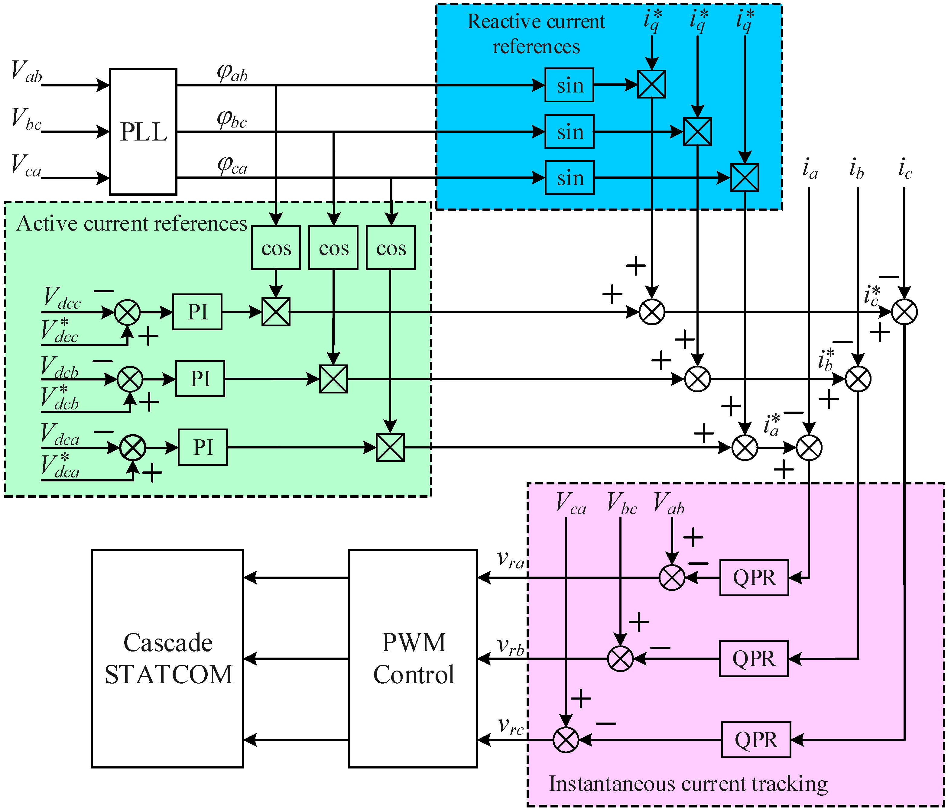
4.2. Control Strategy of Cascade Multilevel STATCOM

As shown in Figure 2, it can be seen that the cascade multilevel STATCOM has three links, and each link of them is independent. Therefore, the cascade multilevel STATCOM can be controlled individually, based on [29], the individual phase instantaneous current control strategy is improved, and then the control strategy of the cascade multilevel STATCOM is shown in Figure 10.
The phase-locked loop (PLL) detects the phase angles of the filtering-winding’s three-phase voltage. The active current references can be generated by a proportional integral (PI) controller in order to maintain its DC voltage constant. The reactive current references (iq*) come from the upper controller, whose value is determined by compensating mode, which will be introduced in next chapter. Adding the active current references and the reactive current reference, the instantaneous current references are formed. Then, a quasi-proportional-resonant (QPR) controller is presented to track the alternating current references for each link, which is able not only to keep high gain, but also reduce the steady-state error at the fundamental frequency. The transfer function of the QPR controller is expressed as
G Q P R ( s ) = k p + 2 k r ω c s s 2 + 2 ω c s + ω 0 2
where kp and kr are the proportional coefficient and resonant gain, respectively; ωc is the equivalent bandwidth of the resonant controller, and ω0 is the fundamental angle frequency. The QPR controller is designed to have the following parameters: kp = 0.5, kr = 20, ωc = 5 rad/s and ω0 = 2π × 50 rad/s. Figure 11 shows the bode plots of the QPR controller. It can be seen that the QPR controller can keep the high gain at the resonant/fundamental frequency and very small at other frequencies, thus the zero steady-state error can be achieved at the resonant/fundamental frequency.
The signals obtained from QPR controller act as the reference voltage, and they will be delivered to the PWM control block after subtracting the voltage value (e.g., Vab, Vbc, and Vca). Finally, the control signals of STATCOM are generated by the PWM control block, and they control the cascade multilevel STATCOM to inject or absorb reactive power for the wind farm.
The wind farm operators expect the power factor to be high, i.e., near 1, when the wind farm operates at the normal condition; in particular, they expect wind turbines to remain connected to the power system under fault conditions. Therefore, the cascade multilevel STATCOM has two compensation modes to meet the requirements of the wind farm, and they are called reactive control mode and voltage control mode. The control block of two compensation modes is shown in Figure 12. In this figure, Vg, Qg, are the voltage and instantaneous reactive power of the grid-side of new grid-connected transformer, respectively. The reactive current references iq* can be obtained by the mean of the switch function. Note that in the reactive control mode, the PI controller obtains the reactive power references, not the reactive current references. The reactive current references can be obtained by
i q * = 2 Q r e f 3 V g
Therefore, at the normal operating condition, the grid voltage is stable and the cascade multilevel STATCOM will provide reactive power to the wind farm to improve the power factor of the wind farm. When a fault or disturbance occurs in public network, the voltage stability is affected, and the STATCOM injects an amount of reactive power for enhancement of voltage stability. Hence, this control strategy reacts immediately to a sudden voltage variation and is well-suitable for improving the LVRT capability of wind farm.

5. Case Study

In order to validate the theoretical analysis and reveal the operating characteristics of the proposed wind power integrated system, the following tests are carried out: (1) the filtering performance; (2) the reactive compensation performance; and (3) the fault recovery performance. All the tests are performed on the simulation model established by in the environment of the Power System Computer Aided Design (PSCAD).

5.1. Test 1: Filtering Performance

In this paper, the measurement data for the real wind farm is obtained. Figure 13 and Figure 14 show the current waveform of grid-winding of the grid-connected transformer, when the output power of the wind farm is 4.5 MW and 15 MW, respectively. From these figures, we can see that the current waveform of the grid-winding represents a clean sinusoidal waveform when implementing the inductive filtering method. Moreover, Figure 15 gives more details about the main order harmonic currents in the grid-winding of the grid-connected transformer. It is clear that, when applying the inductive filtering method, the harmonic currents are reduced greatly, and the total harmonic distortion (THD) is reduced from 23.5% to 6.2%, and from 6.36% to 2.2%, respectively. It is important that there are low 4th-, 5th-, 7th, 11th-order harmonic currents in the grid winding of the grid-connected transformer. Hence, the inductive filtering method can effectively suppress the harmonic currents generated from a wind farm, and the power quality of the public network can be greatly improved.

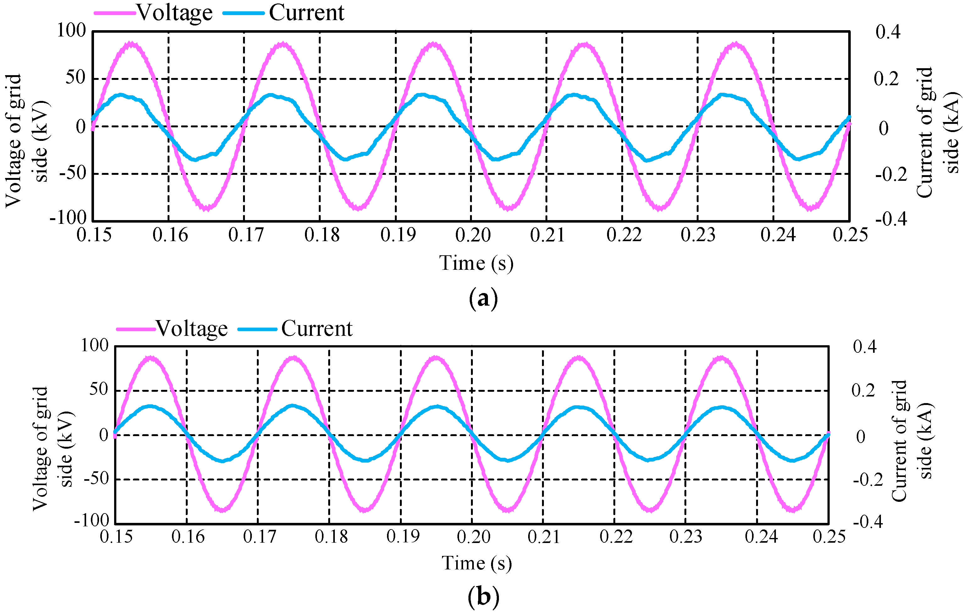
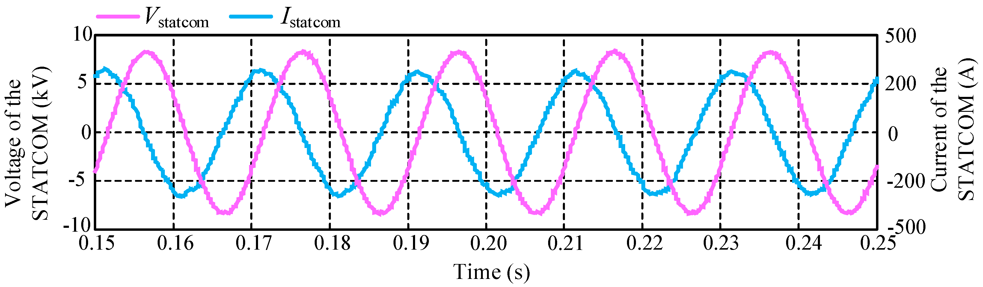
5.2. Test 2: Reactive Power Compensation Performance

Measured data for wind power in a real wind farm is also obtained, as shown in Figure 16. It can be seen from Figure 16 that the active power varies in a wide range, whereas the reactive power fluctuates around −6 Mvar. In this test, the wind power data at 0 h is selected to study the reactive compensation performance of the new wind power integrated system. Table 3 shows the active and the reactive power at the public network side. When using the FT branches and STATCOM, they can compensate for the reactive power of the wind farm. Hoverer, they will consume the active power from wind farm, but to a very small degree. More specifically, the power losses of the STATCOM and the FT branches are 41.2 kW and 7.45 kW, respectively. Table 3 shows the power loss of the new grid-connected transformer with or without the FT branches and the STATCOM. Figure 17 shows the voltage and current at the grid side of the new grid-connected transformer. It can be seen from Figure 17 and Table 3 that the combined implementation of the inductive filtering method and the STATCOM can effectively compensate for the reactive power of the wind farm, hence, the power factor at the public network side is improved effectively. Besides, the combined implementation of the inductive filtering method and the STATCOM can also reduce the power loss of the grid-connected transformer, which means the efficiency of the wind farm can be improved effectively. Moreover, Figure 18 shows the output voltage and current of the STATCOM. It is clear from this figure that the STATCOM provides the reactive power compensation for the wind farm.

5.3. Test 3: Fault Recovery Performance

To investigate the performance of the dynamic voltage improvement of the new wind power integrated system, a three-phase short circuit fault is applied to line 1 of the public network (shown in Figure 2) at 0.6 s, and cleared at 0.65 s. It is worth noting that the protective system of the PMSG, such as a crowbar circuit, is out of service. Figure 19 shows the magnitudes of the voltage at the public network. From Figure 19, it can be seen that, without the implementation of STATCOM, the voltage at the network side becomes lower than 110 kV (1 p.u.), which is disadvantageous for the stable operation of wind farm. When using STATCOM, the voltage is able to return 110 kV after clearing the fault, and the wind farm can successfully ride through the grid fault. The reactive power that STATCOM outputs is shown in Figure 20. It can be found from Figure 20 that when the grid disturbed or fault, the STATCOM will respond immediately and inject an amount of reactive power to support the voltage of the wind farm. Figure 21 shows the output current and command current of STATCOM, especially the command current mentioned in Figure 10. It can be also found from Figure 21 that the STATCOM has a good tracking performance on the output current. In this way, the LVRT capability of wind farm can be greatly improved.

6. Conclusions

This paper proposes a new wind power integrated system based on an inductive filtering method. The new system contains a new grid-connected transformer with the special wiring and impedance designs, the fully-tuned branches and a cascade multilevel STATCOM. The equivalent circuit and the mathematical model are established for the new wind power integrated system. Further, the operating mechanism on the inductive filtering and the reactive power compensation for the wind farm are investigated, and the realization conditions are obtained for implementing the inductive filtering method. Then, the improved instantaneous current control strategy is proposed in this paper. Moreover, the system simulation model is established according to a real-world wind farm and the measured data. The simulation results indicate that the new wind power integrated system can comprehensively improve the power quality of the wind farm, such as harmonic suppression and reactive power compensation. Furthermore, the results indicate that the new system has a good fault recovery performance and represents an enhanced low-voltage ride through capability for the stable and secure operation of wind farm.

Acknowledgments

This work was supported by the national Natural Science Foundation of China (NSFC) under Grant 51377001, 61233008, 61304092 and 51520105011, by the Special Project of International Scientific and Technological Cooperation of China under Grant 2015DFR70850, and by the Science and Technology Project of Hunan Power Company of China under Grant 5216A014002 and 5216A213509X.

Author Contributions

All the authors made contributions to the concept and design of the article; Yanjian Peng is the main author of this work. Yong Li provided good advice and technical guidance for the manuscript; Yong Li, Zhisheng Xu, Ming Wen, Longfu Luo, Yijia Cao and Zbigniew Leonowicz reviewed and polished the manuscript.

Conflicts of Interest

The authors declare no conflict of interest.

References

  1. Keane, A.; Cuffe, P.; Diskin, E.; Brooks, D.; Harrington, P.; Hearne, H.; Rylander, M.; Fallon, T. Evaluation of advanced operation and control of distributed wind farms to support efficiency and reliability. IEEE Trans. Sustain. Energy 2012, 4, 735–742. [Google Scholar] [CrossRef]
  2. Yao, J.; Li, Q.; Chen, Z.; Liu, A. Coordinated control of a DFIG-Based wind-power generation system with SGSC under distorted grid voltage conditions. Energies 2013, 6, 2541–2561. [Google Scholar] [CrossRef]
  3. Konopinski, R.; Vijayan, P.; Ajjarapu, V. Extended reactive capability of DFIG wind parks for enhanced system performance. IEEE Trans. Power Syst. 2009, 3, 1346–1355. [Google Scholar] [CrossRef]
  4. Okedu, K.; Muyeen, S.M.; Takahashi, R.; Tamura, J. Wind farms fault ride through using DFIG with new protection scheme. IEEE Trans. Sustain. Energy 2012, 2, 242–254. [Google Scholar] [CrossRef]
  5. Lu, S.; Wang, L.; Ke, S.; Chang, C.; Yang, Z. Evaluation of Measured Power Quality Results of a Wind Farm Connected to Taiwan Power System. IEEE Trans. Ind. Appl. 2016, 1, 42–49. [Google Scholar] [CrossRef]
  6. Jayaweera, D.; Islam, S. Steady-state security in distribution networks with large wind farms. J. Mod. Power Syst. Clean Energy 2014, 2, 134–142. [Google Scholar] [CrossRef]
  7. Mohod, S.W.; Aware, M.V. A STATCOM-Control Scheme for Grid Connected Wind Energy System for Power Quality Improvement. IEEE Syst. J. 2010, 3, 346–352. [Google Scholar] [CrossRef]
  8. Liang, S.; Hu, Q.; Lee, W. A Survey of Harmonic Emissions of a Commercially Operated Wind Farm. IEEE Trans. Ind. Appl. 2012, 3, 1115–1123. [Google Scholar] [CrossRef]
  9. Tentzerakis, S.T.; Papathanassiou, S.A. An investigation of the harmonic emissions of wind turbines. IEEE Trans. Energy Convers. 2007, 1, 150–158. [Google Scholar] [CrossRef]
  10. Teng, J.H.; Leou, R.C.; Chang, C.Y.; Chan, S.Y. Harmonic current predictors for wind turbines. Energies 2013, 6, 1314–1328. [Google Scholar] [CrossRef]
  11. ENTSO-E Network Code for Requirements for Grid Connection Applicable to All Generators. Available online: http://networkcodes.entsoe.eu/wp-content/uploads/2013/08/130308_Final_Version_NC_RfG1.pdf (accessed on 12 December 2015).
  12. Hasan, K.N.B.M.; Rauma, K.; Luna, A.; Cadela, J.I.; Rodríguez, P. Harmonic Compensation Analysis in Offshore Wind Power Plants Using Hybrid Filters. IEEE Trans. Ind. Appl. 2014, 3, 2050–2060. [Google Scholar] [CrossRef]
  13. Gan, L.; Li, G.; Zhou, M. Coordinated Planning of Large-Scale Wind Farm Integration System and Transmission Network. CSEE J. Power Energy Syst. 2016, 1, 19–29. [Google Scholar] [CrossRef]
  14. Montao, A.F.O.; Carrillo, C.; Cidrás, J.; Dorado, E.D. A STATCOM with Supercapacitors for Low-Voltage Ride-Through in Fixed-Speed Wind Turbines. Energies 2014, 7, 5922–5952. [Google Scholar] [Green Version]
  15. Roncero-Sànchez, P.; Acha, E. Design of a control scheme for distribution static synchronous compensators with power-quality improvement capability. Energies 2014, 7, 2476–2497. [Google Scholar] [CrossRef]
  16. Bai, J.; Gu, W.; Yuan, X.; Li, Q.; Xue, F.; Wang, X. Power quality prediction, early warning, and control for points of common coupling with wind farms. Energies 2015, 8, 9365–9382. [Google Scholar] [CrossRef]
  17. Zheng, Z.; Yang, G.; Geng, H. Coordinated control of a doubly-fed induction generator-based wind farm and a static synchronous compensator for low voltage ride-through grid code compliance during asymmetrical grid faults. Energies 2013, 6, 4660–4681. [Google Scholar] [CrossRef]
  18. Daratha, N.; Das, B.; Sharma, J. Coordination between OLTC and SVC for voltage regulation in unbalanced distribution system distributed generation. IEEE Trans. Power Syst. 2014, 1, 289–299. [Google Scholar] [CrossRef]
  19. Luo, L.; Li, Y.; Xu, J.; Li, J.; Hu, B.; Liu, F. A new converter transformer and a corresponding inductive filtering method for HVDC transmission system. IEEE Trans. Power Deliv. 2008, 3, 1426–1431. [Google Scholar] [CrossRef]
  20. Li, Y.; Luo, L.; Rehtanz, C.; Yang, D.; Rüberg, S.; Liu, F. Harmonic transfer characteristics of a new HVDC system based on an inductive filtering method. IEEE Trans. Power Electron. 2012, 5, 2273–2282. [Google Scholar]
  21. Li, Y.; Luo, L.; Rehtanz, C.; Nakamura, K.; Xu, J.; Liu, F. Study on characteristic parameters of a new converter transformer for HVDC system. IEEE Trans. Power Deliv. 2009, 4, 2125–2131. [Google Scholar]
  22. Xu, Z.; Peng, Y.; Li, Y.; Wen, M.; Luo, L.; Cai, Y.; Cao, Y. Improvement of power quality and dynamic voltage of wind farms using an inductive filtering method. In Proceedings of the 2015 IEEE 15th International Conference on Environment and Electrical Engineering (EEEIC), Rome, Italy, 10–13 June 2015.
  23. Wang, L.; Nhon, D. Stability enhancement of a power system with a PMSG-Based and a DFIG-Based offshore wind farm using a SVC with an Adaotive-Network-Based fuzzy inference system. IEEE Trans. Ind. Electron. 2013, 7, 2799–2807. [Google Scholar] [CrossRef]
  24. Lázaro, E.G.; Bueso, M.C.; Kessler, M.; Martínez, S.M.; Zhang, J.; Hodge, B.M. Probability density function characterization for aggregated large-scale wind power based on Weibull mixtures. Energies 2016, 9, 91. [Google Scholar] [CrossRef]
  25. Papathanassiou, S.A.; Papadopoulous, M.P. Harmonic analysis in a power system with wind generation. IEEE Trans. Power Deliv. 2006, 4, 2006–2016. [Google Scholar] [CrossRef]
  26. Cirrincione, M.; Pucci, M.; Vitale, G. Growing neural gas-based MPPT of variable pitch wind generators with induction machines. IEEE Trans. Ind. Appl. 2012, 3, 1006–1016. [Google Scholar] [CrossRef]
  27. Sainz, L.; Mesas, J.J.; Teodorescu, R.; Rodriguez, P. Deterministic and stochastic study of wind farm harmonic currents. IEEE Trans. Energy Convers. 2010, 4, 1071–1080. [Google Scholar] [CrossRef] [Green Version]
  28. Heathcote, M.J. The J & P Transformer Book; Reed Educational and Professional Publishing: Oxford, UK, 1998. [Google Scholar]
  29. Shi, Y.; Liu, B.; Shi, Y.; Duan, S. Individual phase current control based on optimal zero-sequence current separation for a star-connected cascade STATCOM under unbalanced conditions. IEEE Trans. Ind. Electron. 2016, 3, 2099–2110. [Google Scholar] [CrossRef]
Figure 1. ENTSO-E low-voltage ride through (LVRT) requirement for grid connection.
Energies 09 00302 g001
Figure 2. Main circuit topology of proposed wind farm integrated system.
Energies 09 00302 g002
Figure 3. Wiring scheme of the new grid-connected transformer.
Energies 09 00302 g003
Figure 4. Power coefficient-tip speed ratio (Cp-λ) curves for different blade angles.
Energies 09 00302 g004
Figure 5. Fast Fourier transformation results on the output currents of wind farm operating with different wind power ratios.
Energies 09 00302 g005
Figure 6. Geographical information of the Baolian wind farm.
Energies 09 00302 g006
Figure 7. The single-phase equivalent-circuit model of the new grid-connected transformer with fully-tuned (FT) branches.
Energies 09 00302 g007
Figure 8. The current distribution of the new grid-connected transformer.
Energies 09 00302 g008
Figure 9. Phasor diagram of the voltage and current of the load winding.
Energies 09 00302 g009
Figure 10. Control strategy of cascade multilevel static synchronous compensator (STATCOM).
Energies 09 00302 g010
Figure 11. Bode diagram of the quasi-proportional-resonant (QPR) controller.
Energies 09 00302 g011
Figure 12. Control block of two compensation mode.
Energies 09 00302 g012
Figure 13. Simulation result about currents in the grid-winding of the new grid-connected transformer when wind farm’s output power is 4.5 MW. (a) No filtering; (b) With inductive filtering.
Energies 09 00302 g013
Figure 14. Simulation result about currents in the grid winding of the new grid-connected transformer when wind farm’s output power is 15 MW. (a) No filtering; (b) With inductive filtering.
Energies 09 00302 g014
Figure 15. FFT results on the current waveform in the grid winding. (a) Output power of wind farm is 4.5 MW; (b) Output power of wind farm is 15 MW.
Energies 09 00302 g015
Figure 16. Wind power data in one day with a three-second interval. (a) Active power; (b) Reactive power.
Energies 09 00302 g016
Figure 17. Voltage and current in the grid side of the new grid-connected transformer. (a) Without compensation; (b) With compensation.
Energies 09 00302 g017
Figure 18. A-phase voltage and current of the STATCOM.
Energies 09 00302 g018
Figure 19. Magnitudes of the voltage at the public network.
Energies 09 00302 g019
Figure 20. Reactive power injected from STATCOM.
Energies 09 00302 g020
Figure 21. Output current and command current of the STATCOM.
Energies 09 00302 g021
Table 1. Design parameters of the new grid-connected transformer.
ParametersValue
Rated capacity60 MVA
Winding voltage V1110 kV
Winding voltage V235 kV
Winding voltage V310 kV
Short-circuit impedance Zn120.105 p.u.
Short-circuit impedance Zn130.065 p.u.
Short-circuit impedance Zn230.040 p.u.
No load loss55 kW
Copper loss275 kW
Table 2. Design parameters of the FT branches.
n-OrderCapacity (MVar)Capacitance (μF)Reactance (mH)
4th branch0.514.900042.4410
5th branch1.030.557513.2629
7th branch0.515.590713.2629
11th branch0.515.78405.3052
Table 3. Active power and reactive power at the public network side and power loss of new grid-connected transformer.
ParameterNo CompensationWith Compensation
Active power (MW)16.028216.0531
Reactive power (Mvar)−5.37440.8786
Power factor0.94810.9985
Power loss of transformer (Mvar)0.10450.0845

