
Optimization of Internal Cooling Fins for Metal Hydride Reactors

Mechanical Engineering Department, University of Alaska Fairbanks, Fairbanks, AK 99775, USA
*
Author to whom correspondence should be addressed.
Energies 2016, 9(6), 447; https://doi.org/10.3390/en9060447
Submission received: 25 March 2016
/
Revised: 20 May 2016
/
Accepted: 1 June 2016
/
Published: 9 June 2016
(This article belongs to the Special Issue Hydrogen Production, Separation and Applications)
Abstract
:Metal hydride alloys are considered as a promising alternative to conventional hydrogen storage cylinders and mechanical hydrogen compressors. Compared to storing in a classic gas tank, metal hydride alloys can store hydrogen at nearly room pressure and use less volume to store the same amount of hydrogen. However, this hydrogen storage method necessitates an effective way to reject the heat released from the exothermic hydriding reaction. In this paper, a finned conductive insert is adopted to improve the heat transfer in the cylindrical reactor. The fins collect the heat that is volumetrically generated in LaNi5 metal hydride alloys and deliver it to the channel located in the center, through which a refrigerant flows. A multiple-physics modeling is performed to analyze the transient heat and mass transfer during the hydrogen absorption process. Fin design is made to identify the optimum shape of the finned insert for the best heat rejection. For the shape optimization, use of a predefined transient heat generation function is proposed. Simulations show that there exists an optimal length for the fin geometry.
1. Introduction
In Alaska, interior villages majorly rely on conventional heating power for daily requirements, such as those from combustion-based generators, which use diesel or gasoline as fuels [1]. However, the residents who depend on these fuels are greatly affected by the increasing costs of imported fuels, which are used in heating, electricity generation, and transportation. This negative effect to consumers can be mitigated as Alaska possesses large quantities of renewable energy (RE) resources—especially wind energy. However, wind energy is location-specific; the annual windfall in the coastal regions of Alaska is much greater than that received by towns and villages in the interior of the state. In addition, remote villages pay a higher economic and environmental penalty for their energy generation due to the additional costs required to transport fossil fuel to remote interior regions, including the environmental hazards of storing this fuel which can sometimes result in damaged or leaking fuel tanks, discarded drums and containers, and so forth [2]. The proposal to implement transportable energy storage technologies such as the metal hydride reactor with rapid hydrogen absorption is a very lucrative pursuit. Effective energy-storage methods offer the capability of increasing the energy storage periods up to more than one week in many cases, with even longer-term storage solutions available, specifically when using metal hydride reactor systems to increase the level of efficiency when using hydrogen as a fuel source [3,4,5,6,7,8,9,10,11,12,13].
The benefits of using hydrogen as a fuel source traditionally come with added risks: as a gas, hydrogen can be extremely flammable and requires high energy in order to compress and store in a holding vessel. The metal hydride reactor system eliminates much of these concerns: firstly, the metal hydride powder more efficiently stores hydrogen atoms within its molecular structure versus hydrogen freely stored in the gaseous state, owing to the high uptake capacity. Second, the volume space required for each storage vessel is much smaller when the lanthanum nickel powder is used, saving material, assembly, and fabrication costs and on-site storage space. The pressure at which hydrogen can be stored is significantly lower when using metal hydrides. A third benefit is that the metal hydride renders the hydrogen in a less volatile state, making transportation much safer, further reducing transportation cost to the end consumers.
Introducing the concept of metal hydrides begins with defining their composition, which is a combination of hydrogen and a metal or metal alloy. Via surface chemisorption, these hydrides can absorb a large relative amount of hydrogen per unit volume. In addition, they operate at low pressures, especially when compared to the compressed hydrogen and do not need to be maintained at cryogenic temperatures, which is required for liquid hydrogen [14,15,16]. For these reasons, metal hydrides are considered to be one of the most promising technologies for energy storage. However, their H2 absorption process does necessitate an effective way to reject the heat released from the exothermic reversible hydriding reaction,
Note that M, x, H, and MH denote the metal or metal alloy, non-stoichiometric coefficient, hydrogen, and hydride phase of the metal or metal alloy, respectively. The ΔH term represents the change in enthalpy. As this reaction chemically generates a considerable amount of heat, a method for efficiently rejecting this from the metal hydride reactor is critical to effective system implementation.
The hydride powder itself possesses a low thermal conductivity value, and to this end various research groups have developed methods for improving heat transfer capacity of the material. From efforts to enhance the inherent thermal conductivity of the metal hydride powder [17,18,19,20,21,22] to metal compacts pressed at high pressure [17] and to pellet-shaped geometries known as porous metal hydride [19], all of these advances require sintering under high pressure and the use of an organic binder. However, these technologies require an additional material process and deteriorate the mass transfer of H2 attributed to decreased permeability. Coolant channels or heat transfer fins have been considered because they increase the heat transfer area without creating the aforementioned issues. Transverse or longitudinal cooling fins were used in tubular and box-shaped reactors [10,23,24,25]. A plate-fin type heat exchanger in a rectangular reactor has been experimentally tested [23]. For a tubular reactor, three designs (coolant channels with fins, helical coils, and shell-and-tube) have been optimized and compared [24]. Another study compared a straight channel with a helical coil for internal cooling and also investigated cooling performance improvements by the addition of external transversal fins [25]. A systematic optimization routine for internal fin design was performed to determine geometrical parameters [10].
In this paper, high-conductive finned insert is adopted as the main method for improving the heat rejection from metal hydride powder in a cylindrical reactor. First, multiple-physics modeling is performed to analyze the transient heat and mass transfer during the hydrogen absorption process. Then, a predefined transient heat generation function is proposed to alleviate the complexity of the model. Numerical simulations are carried out with the goal of optimizing the shape of the conductive finned insert during the H2 absorption process. The study is divided by two different cooling conditions. In one case, a refrigerant flows through a tube along the axis of the cylindrical reactor. The heat collected by fins is transferred to the refrigerant. The second case also uses an internally located refrigerant along with external convection on the outer side of the reactor wall for increased thermal cooling. The goal is to minimize the elapsed time for the process via determination of the number and shape of fins while the total volume of the finned insert used remains fixed. Reduction of the hotspot temperatures is the secondary objective. High hotspot temperatures imply an uneven temperature distribution, or a sign of poor volumetric heat transfer. In addition, the particles in hotspots experience a large temperature change in the cycle of hydriding and dehydriding. As a result, large volume expansion, which increases thermal and mechanical stress on the metal hydride powder grains, may cause them to be fractioned into smaller pieces. This can lead to the congestion of finer hydride powder.
2. The Metal Hydride Reactor Model
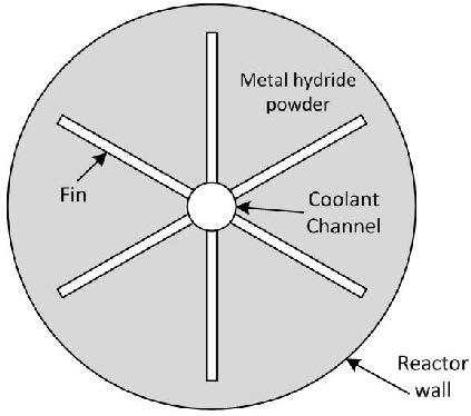
In the metal hydride reactor design, hydrogen is supplied to the cylindrical reactor, which is 100 mm in diameter, and flows through the metal hydride powder along the length of the reactor cylinder as shown in Figure 1. In this study, LaNi5 is selected for the metal hydride powder. Lanthanum nickel powder is one of the most frequently studied and used materials for hydrogen storage, so its physical, chemical, and thermal properties, which the absorption model described in Section 2.1 adopts, are well defined. The refrigerant flows in a 12-mm diameter coolant channel (the central tube) in the axial direction. The reactor cylinder employs a series of internally mounted rectangular fins, which act as an increased cooling surface area to absorb the heat generated from the exothermic hydriding reaction to the refrigerant. These fins are mounted from the exterior surface of the central tube and extend radially outward at predetermined lengths and aspect ratios. This configuration lends to cooling via conduction heat transfer from the metal hydride powder within the reactor to the central tube, and the heat is then rejected as the refrigerant changes its phase from liquid to vapor. The rate of the refrigerant is controlled such that the temperature of the surface where it boils is maintained at 10 °C. The model assumes that the central tube is thin enough so that the thermal resistance due to the conduction through the tube is a fraction of that due to the convection and consequently can be ignored. For the case of cooling by both the refrigerant of the central tube and the coolant flowing over the outside of the reactor wall, the environment is analyzed at a value of 500 W/m2·K for the convective heat transfer coefficient of the coolant, which is a generally accepted mean value for a liquid coolant. A specified heat flux boundary condition is considered on the reactor wall, unlike the central tube with fixed temperature. This is because one of the most feasible ways to cool multiple reactors is in-line or via staggered banks of reactor cylinders with a single phase coolant.
2.1. Hydriding Process
Based on the processes of heat generation via exothermic reactions for the chemical hydriding process, along with flow in porous mediums, and also considering the mass conservation of hydrogen-absorbed metal, the full description of the LaNi5 metal alloy can be accurately modeled. This procedure is described in the proceeding section. Beginning with the mass conservation of the hydrogen-absorbed metal hydride is the diffusion of hydrogen occurs into the LaNi5 powder:
considering that the diffusivity of hydrogen, D, in LaNi5 is referenced by [26].
The density of the LaNi5 metal hydride powder increases as it absorbs hydrogen and thus is solved from the preceding mass equation. The temperature distribution in the metal hydride powder is identified by the energy conservation equation:
Examination of the heat generation identifies the enthalpy of formation, ΔH, to be the source of the temperature increase. At this point, two assumptions are made: (1) that gas temperature remains constant at room temperature to assist with computational processing load; and (2) that the hydrogen gas density as obtained from the ideal gas law is valid for further calculations. Further simplification neglects the effects of heat transfer between metal hydride powders and surrounding hydrogen gas. Furthermore, it can be assumed that the viscous dissipation and compression work due to the H2 in the reactor bed are negligible. For the absorption process, the mass flow rate is described by,
Incorporation of Van’t Hoff’s relationship for pressure at constant temperature states is also given by the proceeding equation, with equilibrium pressure in units of atm,
where the Van’t Hoff constants are A = 13.18 and B = 3631 K [27].
COMSOL, a commercial partial differential equation solver [28] was used to evaluate numerical computations to solve multiple physics reaction processes as described by Equations (2)–(6). For the fin material, aluminum 2024 T6 (thermal conductivity: 177 W/m·K) was selected, while the thermal conductivity of LaNi5 powder was set to a value of 2 W/m·K, and the H2 supply pressure valued at 1.013 MPa. The refrigerant that runs through the central tube was assumed to change its phase at a saturation temperature at 10 °C. Initial temperature is also set at 10 °C for the metal hydride powder and the fins.
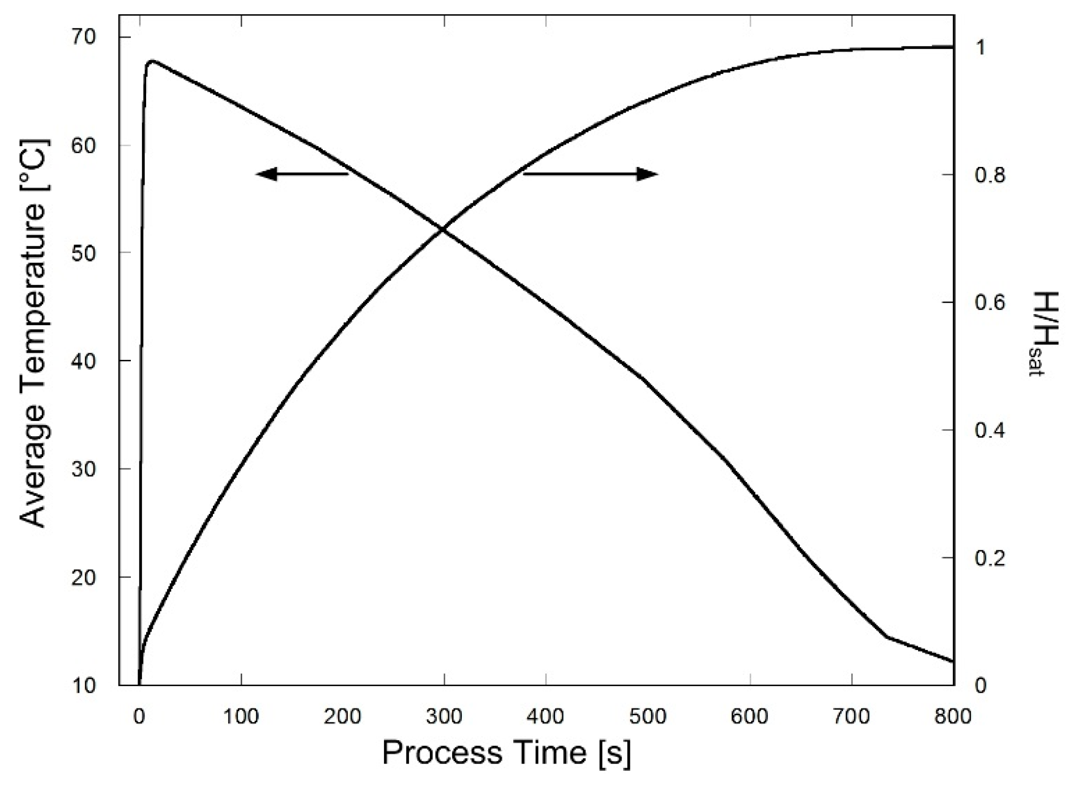
Figure 2 describes the simulation results of the hydriding process for the case of 8 fins without the external convection on the outer surface of the reactor wall. The volume averaged temperature of metal hydride powder and the ratio of mass of absorbed H2 to the saturation mass (H/Hsat) are plotted in the left and right ordinates, respectively.
It is observed that the hydriding rate begins at a high value and then slows, which is due to the delay caused by slow heat transfer. Thus, a resulting increase in temperature occurs for the first 15 s, after which this too exhibits a gradual decrease in time. At least 90% of the H2 is absorbed within 500 s. It can be deduced that an improved fin structure can contribute to decreased time required for absorption overall. The optimal shape of the fins is further discussed in detail in Section 3.
2.2. Heat Generation Model
The hydriding process for metal hydride reactors can be described as follows: in the boundary between the central refrigerant channel and the interstitial metal hydride powder, the Dirichlet boundary condition is included. Considering that the Dirichlet boundary condition is valid for this model because the heat transfer coefficient of the evaporation is of very high value so that the temperature of the surface can be viewed as a constant value with negligible error.
In an effort to reduce the computational processing time, the hydriding process model described in Section 2.1 is simplified to transient heat conduction with predefined time-variable heat generation properties, and exothermic reactions are simulated as pulse-frequency volumetric heat generation. The last term (1 − ε)·m·ΔH per unit volume in Equation (4) is therefore replaced by a sinusoidal function:
A peak heat generation rate of 5.0 W/cm3 makes Equation (7) equivalent to the actual calculated heat generation value; thus, it is used for the rest of simulations. This simplified approach reduces the number of degrees of freedom from approximately 15,900 to 3,500 for the numerical simulation environment described in Section 3 and Figure 3. Computation time is also reduced by 72.2%.
3. Fin Optimization
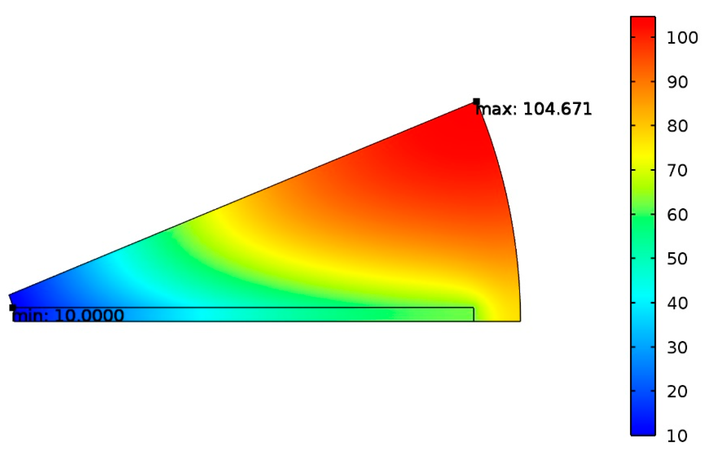
The optimization incorporates the study of all the design conditions described in the previous sections, taking into consideration specifically the number of fins and their aspect ratio. This report maintains a volume fraction of φ = 0.1 in the calculations, which is defined as the volume occupied by the fins over the total volume occupied by the metal hydride powder if no fins are present. As such, the cross-sectional area of all fins is defined by φπ, where and are the outer radius of the central cooling tube and the inner radius of the reactor wall, respectively. The optimization begins with the determination of the most suitable aspect ratio with a fixed number of fins. Here, the COMSOL multi-physics simulation software is used to calculate the transition heat transfer numerically with a model using more than 1,000 individual elements, a time step of 0.1 s, and a dimensional tolerance of 10−8 m. The mesh size was determined such that the relative error of numerical results fell within 1% when the mesh size was halved at every step. An example of the thermal distribution on the reactor cross section is displayed in Figure 3. This eight-fin reactor has an aspect ratio (AR) of 0.06048 (2.419 mm × 40.00 mm). Figure 3, which exhibits temperatures 60 s after the hydriding process, illustrates that the minimum temperature is located at the center of the cooling cylinder, while the maximum temperature is at the inner surface of the reactor wall. In order to minimize the computational load for the simulation, only half of the fin geometry is analyzed below. As the fin is symmetrical about the longitudinal axis, this is a sound practice.
3.1. Optimization of Aspect Ratio
One of the key parameters in the optimization of the design is that of the aspect ratio (AR). Within the realm of possible values for the parameter, there exists an optimal AR, which best applies to the design and therefore yields the most effective cooling with a fin geometry that is neither too long nor too short. As an example, referencing the eight-fin design in Figure 3, the fin’s aspect ratio can be altered to yield a beneficial result of dispersing thermal hotspots and improving the heat transfer away from the metal hydride powder towards the fins themselves. Furthermore, the time required for cooling can be minimized to achieve the desired 15 °C at any given thermal hotspot. To this end, Figure 4 shows a plot of the volume-averaged temperature versus the elapsed time for two distinct fin AR’s. The cooling time required, for example, to achieve 30 °C exhibits a large time difference (approximately 210 s for AR = 0.0605 versus 300 s AR = 0.1075). The difference in cooling time therefore contributes to improved hydrogen absorption from the metal hydride hydriding process.
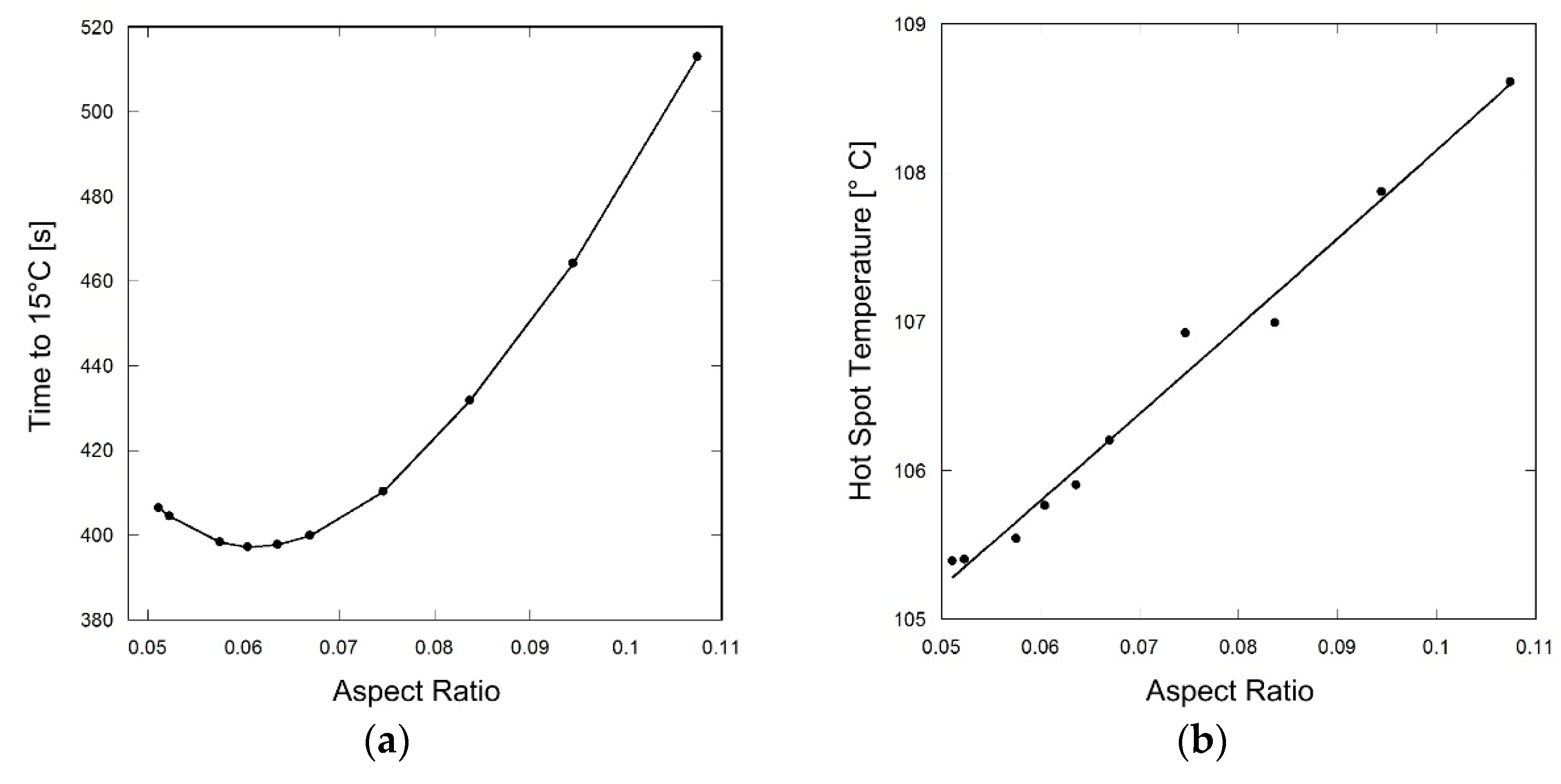
The results of the COMSOL simulation on the eight-fin design are plotted in Figure 5, where it is clear to see that the optimal AR is located at the lowest region of the parabolic curve. For example, in the Figure 5a graph, the optimum design in terms of time needed to achieve cooling to 15 °C is found at an AR of 0.0605, with a corresponding cooling time of 397 s. An examination of the hotspot temperature curve shown in Figure 5b illustrates that the observed hotspot temperature has a minimum value of 105.4 °C for AR = 0.0511, compared with the maximum value of 108.7 °C at an AR of 0.1075. This range of values between minimum and maximum temperatures illustrates that a reduction in hotspot temperature by 3.3 °C can be achieved with simple modifications to fin geometry.
From the curve plots in Figure 5a,b, it can be clearly observed that the optimal AR exists below 0.07 and that a dramatic increase in time exists in the time required to cool down to 15 °C along with the associated hotspot temperatures when this AR is greater than 0.08. Therefore, the optimum AR is determined by variation of the fin length and thickness to values, which yield maximum efficacy. If optimization is not carried out—for example, if a fin is designed too short—the thermal transport phenomenon becomes slow to cool localized hotspots occurring along the outer radius of the interior of the reactor due to the increased distance between the hotspot and the fin tip. Alternatively, if a fin length is designed too long and too thin, this also causes an increase in the average temperature, resulting from the widening hot area, which is attributed to decreased conductance of the thin fin.
3.2. Optimization of Number of Fins
The number of fins used is a critical factor in reactor design. Noting that a fixed volume fraction is given at φ = 0.1, the optimal number of fins is desired from this value. Reactor designs with different fin numbers (N) have been examined numerically in a method similar to that described in Section 3.1. This optimization process begins with the N = 3 fin design. Here, the minimum time required to cool to 15 °C and the lowest hotspot temperature are found by varying AR via the procedure described in the previous section. Continuation of this procedure includes subsequent values of N = 4, 5, 6, 8, 12, 18, 36, and 72 fins.
In Figure 6, the results from COMSOL simulations show the minimum time required to cool down to 15 °C as well as the lowest hotspot temperature. As is seen, the reactor model shows improved performance with an increased number of fins. Viewing this simulation data, one can see that the cooling time required for the three-fin design is 957 s, which can be compared to the eight-fin design, which requires 397 s. This trend of a decrease in the required time to reach 15 °C continues asymptotically towards the 72-fin design. Additionally, the hotspot temperature also decreases with increasing number of fins. However, an increased fin number also adds to the overall complexity of the reactor model, which can be detrimental to the construction, assembly, and maintenance of the model.
When considering the balancing effects of model complexity to cooling efficiency, there is no longer any reasonable benefit to increasing the total number of fins after N = 18. At this point, an increased cooling with additional numbers of fins does not offset the cost of increased model complexity, nor is there any appreciable hydrogen absorption process time or a drop in hotspot temperature. Again, many fins will contribute to an increased internal complex design structure.
3.3. External Convective Cooling
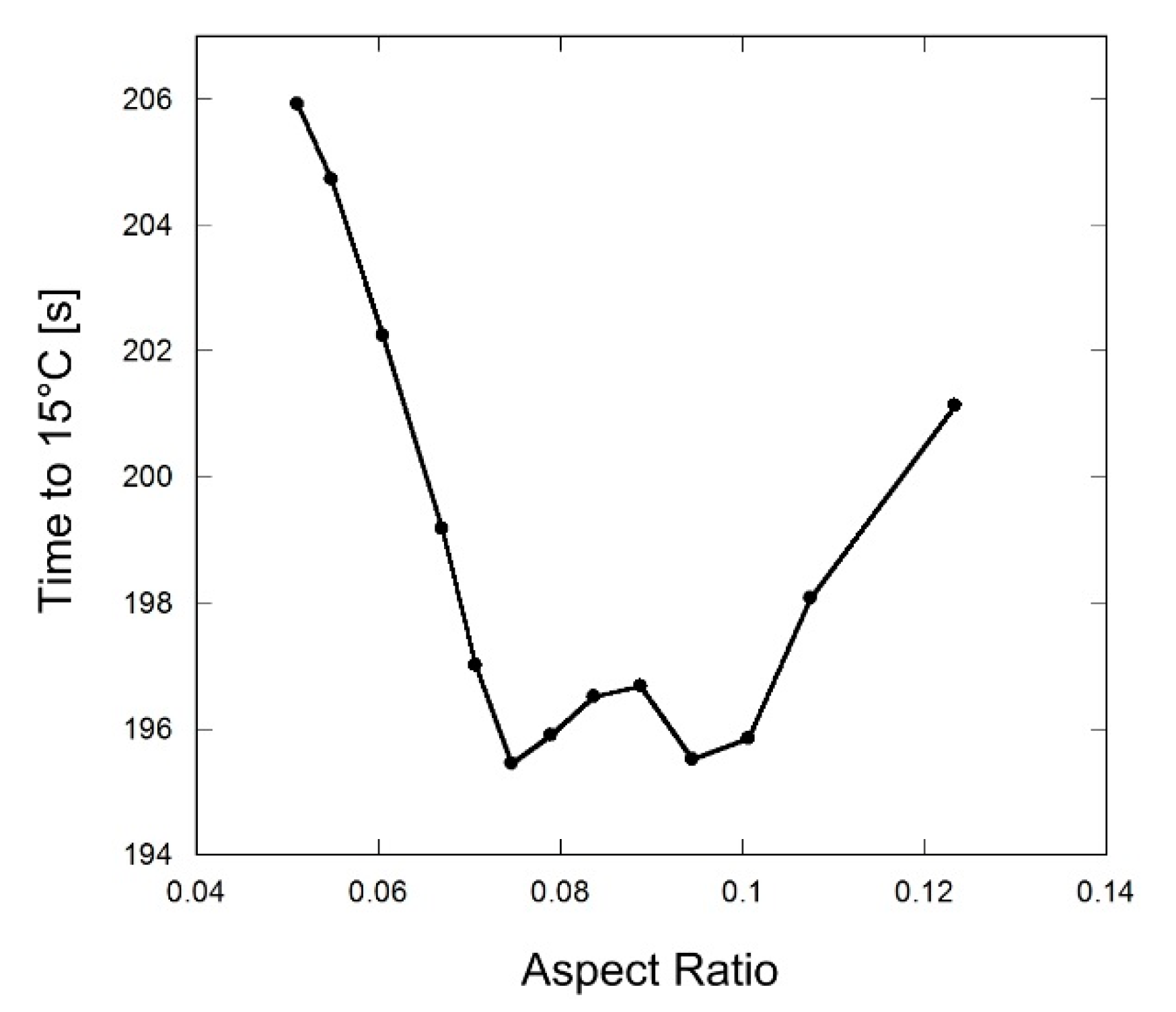
A new design consideration is taken for the two cooling sources condition. In addition to cooling from the refrigerant flowing through the center of the reactor, external convection cooling from outside the reactor is analyzed. Here again, the volume fraction remains at φ = 0.1, as in the previous simulations. Computational analysis is accomplished by varying the AR for the time required to cool to 15 °C along with minimum hotspot temperature. In Figure 7, the “pizza slice” shape, which is cut along symmetric geometrical lines, is representative of a sector of the reactor with half of one fin shown, and the interstitial area composed of the metal hydride metal powder of the eight-fin reactor design. Furthermore, the effect of convective cooling from the external environment is taken into account here, which is defined by 500 W/m2·K.
Figure 7 shows that the majority of hotspot activity occurs within the interstitial area between the fin area and the outer radius of the interior of the reactor. In this region, the maximum observed temperature occurs at 83.24 °C at a time of 60 s during the simulation. In comparison with Figure 3, it is plain to see that this in an improvement, as the maximum observed temperature is lower (approximately by 21 °C), and the physical location of this maximum temperature is located further into the reactor chamber rather than just at the reactor model outer radius. Another improvement of this cooling condition from the previous is the overall thermal distribution of the hotspot maximum temperature within the reactor. As previously stated, any localized masses of metal hydride powder will generate increased thermal resistance, which can result in increased hotspot activity and can subsequently lead to detrimental material side effects such as early fatigue. The additional cooling mitigates this unwanted effect with the help of fins, and the resulting thermal pattern is more evenly distributed.
The simulation reveals that an optimum AR exists for the same reasons as described in Section 3.2 for fin designs that are too short or too long. Fins that are too short (high AR) will be ineffective in cooling the hotspot located far from the fin tip, whereas fins that are too long and too thin (low AR) will be slow to conduct heat through the fin. Figure 8 illustrates this concept further in the capacity of time required to cool to 15 °C for the eight-fin reactor model in AR > 0.11 and AR < 0.06, representing fins that are too short and too long, respectively.
In Figure 8, an interesting behavior exists where two optimum aspect ratios produce nearly the same amount of required time to reach 15 °C in cooling, which was not observed for the case of the single cooling source. At 0.075 and 0.094 ARs, shown at the two-pronged base of Figure 8, the cooling time is nearly equivalent at 195 s. From a design perspective, this is advantageous during physical construction and assembly, as two options are available, both of which achieve maximum cooling effects. This trait offers more flexibility via engineering design. The mechanics of why these two optimum points exist is explained as follows: (i) In the case of the 0.094 AR, which is for a shorter-length fin, the local hotspot occurs adjacent to outer edge of the fin. Here, the heat from the hotspot travels by slow conduction through the metal hydride powder for relatively short distance, and then by fast conduction through the fin material to the central cooling core where the refrigerant flows; (ii) In the case of the 0.075 aspect ratio, which is for a longer-length fin, the heat is removed from the system via the relatively thin fin material, but not all heat collected by the fin is transferred to the central cooling refrigerant. The long fin also acts as a heat path to the external cooling. The two cases and their respective cooling effects contribute equally; thus, their time required to reach 15 °C is approximately the same.
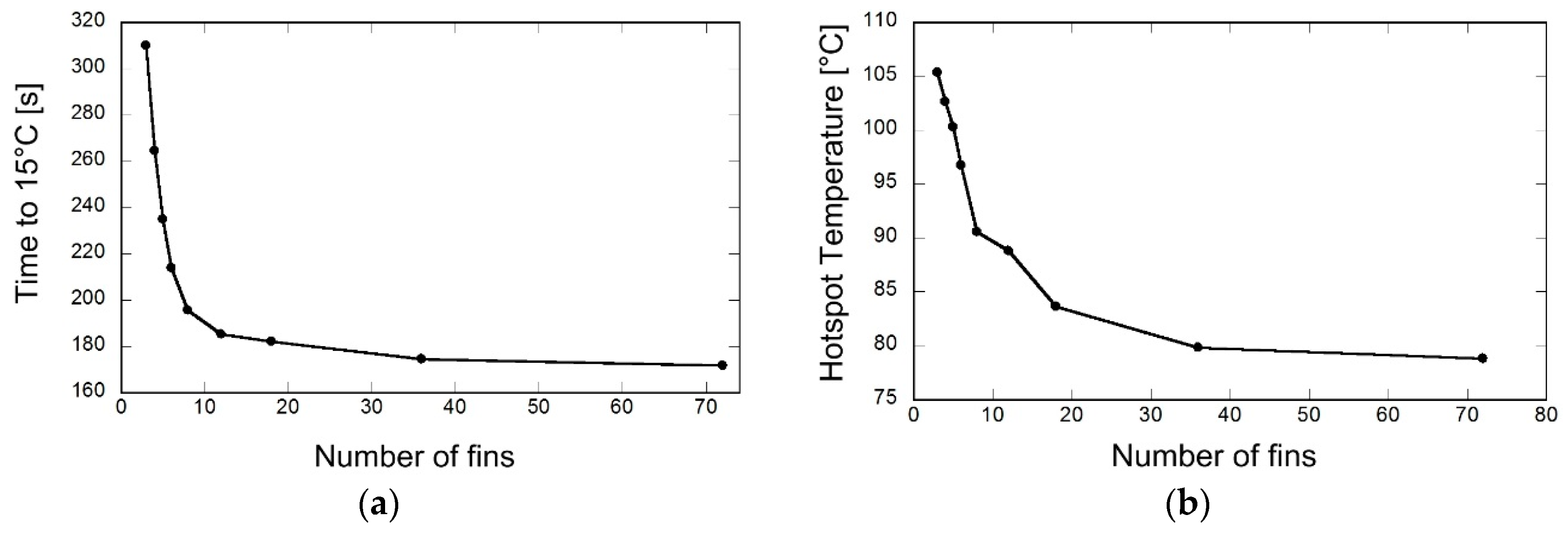
When considering the optimum number of fins to reach 15 °C during cooling, this simulation analyzes the procedure in a similar method to what was described in Section 3.2. Figure 9a illustrates the results of this analysis, which yields a cooling performance curve similar to that of Figure 6a. The number of fins analyzed for this simulation are N = 3, 4, 5, 6, 8, 12, 18, 36, and 72 fins.
Here again, it can be noted that there is a maximum cooling performance-to-cost value for total number of fins at N = 18. Once again, an increase in the number of fins from this value will lead to increased complexity of the reactor model without any significant thermal cooling performance. Furthermore, it can be validated that, if N = 18, there is a high degree of cooling being performed within the reactor and is much improved than if N < 18.
The hotspot locations and temperatures are also of critical concern in the analysis, and this is considered in Figure 9b where optimization of the number of fins, as previously discussed, yields a plot curve similar to that, which was developed in Section 3.2, Figure 6b. Here, it is seen that for N = 8, the observed hotspot temperature is approximately 90 °C, which is an improvement from the model in Figure 9b, where, for the same number of fins, the observed hotspot temperature is 105.4 °C, and the hotspot temperature for the new convective cooling design is approximately 15.4 °C lower by comparison. This increased cooling performance can be attributed, in part, to the addition of the effect of external convective cooling from the exterior environment, with all other factors being held equivalent in the two models.
4. Conclusions and End Remarks
This paper showed that the hydriding process time to cool to 15 °C and hotspot temperature reduction could be improved simultaneously by the optimal aspect ratio of the fin while the volume fraction ratio was fixed to 0.1. We explored the merits of the hydriding process time in two cases: case (i): cooling with refrigerant circulating inside a tube at the center of the reactor with fins; case (ii): the conditions in the previous case along with external convective cooling from outside of the hydrogen reactor. The simulation study revealed that, in both cases, the optimal aspect ratio of the rectangular fins reduces the hydration process time needed to cool and diminishes the hotspot temperature in a cylindrical metal hydride reactor. The optimal aspect ratios of the fins were determined, and optimum numbers of fins for improved heat transfer performance were suggested to avoid an overly complex structure and manufacturing process time. If the design complexity and the manufacturing process is not a factor to consider, a design with a high number of fins is recommended.
Comparisons were made between the two cooling cases. For the N = 8 fins reactor, an improved heat rejection performance from case (ii) can be described by the following observations:
- (1)
- The time required for the model to reach 15 °C for case (i) was measured at 397 s at fin aspect ratio of 0.0605, while case (ii), which incorporated external convection cooling, improved upon this time with a value of 195 s at a fin aspect ratio of 0.075. The simulation study also validates that there is an optimal aspect ratio, which must be considered in the design specifications in order to acquire substantial results in heat transfer performance.
- (2)
- Observations of the maximum hotspot temperature within the reactor revealed that case (i) generated a high value at 88 °C, while in case (ii) the external cooling convection model lowered this reading to 80 °C, thereby lowering overall temperatures within the reactor chamber itself.
- (3)
In the present study, fin geometry (the aspect ratio and number of fins) was optimized while the reactor’s geometry, material, and cooling conditions on the boundary were fixed. This means that a different reactor size or different cooling conditions will change the optimal fin geometry. However, the results reveal that there is an optimum point for the case of sole internal cooling and that there are two local optimum points for the case of combined internal and external cooling. The present method for fin geometry optimization makes a fair comparison since it uses a constant volume of fin materials, which also means a constant amount of metal hydride. In the future, a non-dimensional modeling approach will be used to provide a greater generality of optimization results. The effect of change in the volume fraction ratio of the fins will also be worth a thorough investigation.
Acknowledgments
We express our gratitude for the partial financial aid toward the publication fee provided by the Vice Chancellor for Research of the University of Alaska Fairbanks.
Author Contributions
Both Vamsi Krishna Kukkapalli and Sunwoo Kim developed the mathematical model and incorporated it into COMSOL. Vamsi Krishna Kukkapalli performed the simulations. Sunwoo Kim analyzed the simulation results. Both authors wrote the paper.
Conflicts of Interest
The authors declare no conflict of interest.
Abbreviations
The following abbreviations are used in this manuscript:
| RE | renewable energy |
| AR | aspect ratio |
| Nomenclature | |
| c | concentration of the hydrogen, mol·m−3 |
| cp | specific heat of metal hydride, J·kg−1·K−1 |
| Ca | constant |
| Ea | activation energy, J·mol−1 |
| Ha | activation enthalpy, eV |
| k | thermal conductivity, W·m−1·K−1 |
| kb | Boltzmann constant, eV·K−1 |
| m | mass, kg |
| pin | hydrogen supply pressure, Pa |
| R | reaction rate, mol·m−3·s−1 |
| Ru | universal gas constant, J·mol−1·K−1 |
| t | time, s |
| T | Temperature, K |
| Greek Letters | |
| ε | porosity |
| density, kg·m−3 | |
| Subscripts | |
| 0 | initial state |
| eq | equilibrium |
| g | hydrogen gas |
| m | metal hydride powder |
| sat | staturation |
References
- Leighty, W. Alaska village survival: Affordable energy independence via renewables firmed as hydrogen storage in liquid anhydrous ammonia. In Proceeding of NHA Conference and Hydrogen Expo 2009, Columbia, SC, USA, 30 March–2 April 2009.
- Isherwood, W.; Smith, J.R.; Aceves, S.M.; Berry, G.; Clark, W.; Johnson, R.; Das, D.; Goering, D.; Seifert, R. Remote power systems with advanced storage technologies for Alaskan villages. Energies 2000, 25, 1005–1020. [Google Scholar] [CrossRef]
- Rosen, M.A. The prospects for renewable energy through hydrogen energy systems. J. Power Energy Eng. 2015, 3, 373–377. [Google Scholar] [CrossRef]
- Gahleitner, G. Hydrogen from renewable electricity: An international review of power-to-gas pilot plants for stationary applications. Int. J. Hydrog. Energy 2013, 38, 2039–2061. [Google Scholar] [CrossRef]
- Dodds, P.E.; Staffell, I.; Hawkes, A.D.; Li, F.; Grünewald, P.; McDowall, W.; Ekins, P. Hydrogen and fuel cell technologies for heating: A review. Int. J. Hydrog. Energy 2015, 40, 2065–2083. [Google Scholar] [CrossRef]
- Corgnale, C.; Hardy, B.J.; Tamburello, D.A.; Garrison, S.L.; Anton, D.L. Acceptability envelope for metal hydride-based hydrogen storage systems. Int. J. Hydrog. Energy 2012, 37, 2812–2824. [Google Scholar] [CrossRef]
- Nyamsi, S.N.; Yang, F.; Zhang, Z. An optimization study on the finned tube heat exchanger used in hydride hydrogen storage system—Analytical method and numerical simulation. Int. J. Hydrog. Energy 2012, 37, 16078–16092. [Google Scholar] [CrossRef]
- Souahlia, A.; Dhaou, H.; Askri, F.; Sofiene, M.; Jemni, A.; Ben Nasrallah, S. Experimental and comparative study of metal hydride hydrogen tanks. Int. J. Hydrog. Energy 2011, 36, 12918–12922. [Google Scholar] [CrossRef]
- Souahlia, A.; Dhaou, H.; Mellouli, S.; Askri, F.; Jemni, A.; Ben Nasrallah, S. Experimental study of metal hydride-based hydrogen storage tank at constant supply pressure. Int. J. Hydrog. Energy 2014, 39, 7365–7372. [Google Scholar] [CrossRef]
- Garrison, S.L.; Hardy, B.J.; Gorbounov, M.B.; Tamburello, D.A.; Corgnale, C.; Vanhassel, B.A.; Mosher, D.A.; Anton, D.L. Optimization of internal heat exchangers for hydrogen storage tanks utilizing metal hydrides. Int. J. Hydrog. Energy 2012, 37, 2850–2861. [Google Scholar] [CrossRef]
- Ronnebro, E.C.E.; Whyatt, G.; Powell, M.; Westman, M.; Zheng, F.; Fang, Z.Z. Metal hydrides for high-temperature power generation. Energies 2015, 8, 8406–8430. [Google Scholar] [CrossRef]
- McWhorter, S.; O’Malley, K.; Adams, J.; Ordaz, G.; Randolph, K.; Stetson, N.T. Moderate temperature dense phase hydrogen storage materials within the US department of energy (DOE) H2 storage program: Trends toward future development. Crystals 2012, 2, 413–445. [Google Scholar] [CrossRef]
- Felderhoff, M.; Bogdanović, B. High temperature metal hydrides as heat storage materials for solar and related applications. Int. J. Mol. Sci. 2009, 10, 325–344. [Google Scholar] [CrossRef] [PubMed]
- Sakintuna, B.; Lamari-Darkrim, F.; Hirscher, M. Metal hydride materials for solid hydrogen storage: A review. Int. J. Hydrog. Energy 2007, 32, 1121–1140. [Google Scholar] [CrossRef]
- Akiba, E.; Nomura, K.; Ono, S. Kinetics of the reaction between Mg-23.3%Ni eutectic alloy and hydrogen. J. Less Common Met. 1983, 89, 145–150. [Google Scholar] [CrossRef]
- Muthukumar, P.; Maiya, M.P.; Murthy, S.S. Experiments on a metal hydride based hydrogen compressor. Int. J. Hydrog. Energy 2005, 30, 879–892. [Google Scholar] [CrossRef]
- Lloyd, G.; Kim, K.J.; Razani, A.; Feldman, K.T., Jr. Thermal conductivity of porous metal hydrides. J. Thermophys. Heat Transf. 1998, 12, 132–137. [Google Scholar] [CrossRef]
- Ron, M.; Bershadsky, E.; Josephy, Y. Thermal conductivity of PMH compacts, measurements and evaluation. Int. J. Hydrog. Energy 1992, 17, 623–630. [Google Scholar] [CrossRef]
- Congdon, J.W. Metal Hydride Composition and Method of Making. U.S. Patent 1995. [Google Scholar]
- Dieterich, M.; Pohlmann, C.; Bürger, I.; Linder, M.; Röntzsch, L. Long-term cycle stability of metal hydride-graphite composites. Int. J. Hydrog. Energy 2015, 40, 16375–16382. [Google Scholar] [CrossRef]
- Kim, K.J.; Montoya, B.; Razani, A.; Lee, K.-H. Metal hydride compacts of improved thermal conductivity. Int. J. Hydrog. Energy 2001, 26, 609–613. [Google Scholar] [CrossRef]
- Klein, H.P.; Groll, M. Heat transfer characteristics of expanded graphite matrices in metal hydride beds. Int. J. Hydrog. Energy 2004, 29, 1503–1511. [Google Scholar] [CrossRef]
- Oi, T.; Maki, K.; Sakaki, Y. Heat transfer characteristics of the metal hydride vessel based on the plate-fin type heat exchanger. J. Power Sources 2004, 125, 52–61. [Google Scholar] [CrossRef]
- Raju, M.; Kumar, S. Optimization of heat exchanger designs in metal hydride based hydrogen storage systems. Int. J. Hydrog. Energy 2012, 37, 2767–2778. [Google Scholar] [CrossRef]
- Sekhar, B.S.; Lotoskyy, M.; Kolesnikov, A.; Moropeng, M.; Tarasov, B.; Pollet, B. Performance analysis of cylindrical metal hydride beds with various heat exchange options. J. Alloys Compd. 2015, 645, S89–S95. [Google Scholar] [CrossRef]
- Majer, G.; Kaess, U.; Bowman, R.C., Jr. Nucler magnetic resonance studies of hydrogen diffusion in LaNi5H6 and LaNi4.8Sn0.2H5.8. Phys. Rev. B 1998, 57, 13599–13603. [Google Scholar] [CrossRef]
- Inomata, A.; Aoki, H.; Miura, T. Measurement and modelling of hydriding and dehydriding kinetics. J. Alloys Compd. 1998, 278, 103–109. [Google Scholar] [CrossRef]
- COMSOL multiphysics modeling software. For more information about COMSOL multiphysics. Availabe online: https://www.comsol.com/ (accessed on 14 March 2016).
Figure 1.
Cross-sectional view of the six-fin reactor model with the central cooling.

Figure 2.
The volume-average temperature of metal hydride and hydrogen absorption over the process time.
Figure 2.
The volume-average temperature of metal hydride and hydrogen absorption over the process time.

Figure 3.
Temperature distribution of eight-fin reactor at 60 s (temperature in °C).

Figure 4.
The average temperature of the metal hydride for the aspect ratio of 0.0605 and 0.1075.

Figure 5.
The results of simulations for the eight-fin reactor. (a) Time required to cool to 15 °C; (b) Hot spot temperature.
Figure 5.
The results of simulations for the eight-fin reactor. (a) Time required to cool to 15 °C; (b) Hot spot temperature.

Figure 6.
The effect of the number of fins on the heat transfer. (a) Time required to cool to 15 °C; (b) Hot spot temperature.
Figure 6.
The effect of the number of fins on the heat transfer. (a) Time required to cool to 15 °C; (b) Hot spot temperature.

Figure 7.
Temperature distribution of the eight-fin reactor for the case of convection at 60 s (temperature in °C).
Figure 7.
Temperature distribution of the eight-fin reactor for the case of convection at 60 s (temperature in °C).

Figure 8.
The time required to cool down to 15 °C for eight-fin reactor with convection on the reactor cylinder wall.
Figure 8.
The time required to cool down to 15 °C for eight-fin reactor with convection on the reactor cylinder wall.

Figure 9.
The effect of the number of fins on the reactor with cooling from the external wall as well as the central channel. (a) Time required to cool to 15 °C; (b) Hot spot temperature.
Figure 9.
The effect of the number of fins on the reactor with cooling from the external wall as well as the central channel. (a) Time required to cool to 15 °C; (b) Hot spot temperature.
© 2016 by the authors; licensee MDPI, Basel, Switzerland. This article is an open access article distributed under the terms and conditions of the Creative Commons Attribution (CC-BY) license (http://creativecommons.org/licenses/by/4.0/).
Share and Cite
MDPI and ACS Style
Kukkapalli, V.K.; Kim, S. Optimization of Internal Cooling Fins for Metal Hydride Reactors. Energies 2016, 9, 447. https://doi.org/10.3390/en9060447
AMA Style
Kukkapalli VK, Kim S. Optimization of Internal Cooling Fins for Metal Hydride Reactors. Energies. 2016; 9(6):447. https://doi.org/10.3390/en9060447
Chicago/Turabian StyleKukkapalli, Vamsi Krishna, and Sunwoo Kim. 2016. "Optimization of Internal Cooling Fins for Metal Hydride Reactors" Energies 9, no. 6: 447. https://doi.org/10.3390/en9060447
Note that from the first issue of 2016, this journal uses article numbers instead of page numbers. See further details here.