1. Introduction
The always-increasing energy demand imposes the investigation of new form of energy supply, which must match with some fundamental requirements, such as:
- (1)
Providing reliable and continuous base-load power;
- (2)
Providing peak-load power when needed;
- (3)
Being the “greenest” possible; and
- (4)
Being tailored according to the different necessities.
Renewable energies reply surely to the previous point 3, but their intermittent nature has a large impact in terms of low capacity factors, low flexibility, and amortization costs.
Probably the only path to follow is, therefore, the integration of different technologies, in order to use them, separately or simultaneously, according to the actual necessities and conditions.
The “HRC-Power” project (Hybrid Renewable energy Converter for continuous and flexible Power production) aims at replying all the aforementioned requirements, integrating both combustion and solar concentration modes, into miniaturized items.
Miniaturization, mandatory for a device with the aim of being usable even for very small energy demands, imposes strategies to overcome the typical drawbacks of miniaturized combustion systems; that is, incomplete combustion and flame instability [
1].
In the light of the above, the HRC-Power project designs the integration of a parallelepiped brick, characterized by emitting walls, with internal micro-meso swirling combustion chambers (this integration is under a pending patent [
2]).
The parallelepiped brick delivers, to the external ambient environment, thermal energy via the emitting walls that are heated up by the sun and/or by the heat released during the chemical combustion taking place inside the swirling combustion chambers.
That thermal energy is finally converted into electrical energy by a thermo-photovoltaic system (TPV).
The real potentialities of this integration are analyzed in [
1]. In particular, numerical simulation of a parallelepiped emitting brick with two internal micro-meso swirling chambers, fed by H
2/air with 400 W of injected thermal power, at different equivalence ratios and with different chamber diameters, are carried out.
Results were encouraging in terms of delivered power and of peak surface temperature.
Once demonstrated, with the work in [
1], that the overall system would work properly, new and more specific design requirements have been defined in order to make the overall micro-system compatible with a thermal/electrical conversion by thermo-photovoltaic cells.
The new design requirements were:
- -
The emitting surface dimensions equal to 30 × 30 mm;
- -
The converter thermal resistance efficiency, in the solar mode operation, ηTR ≥ 20% (see Equation (1));
- -
The peak temperature on the emitting surface, in the combustion mode operation, Tpeak emitting surface > 1000 K; and
- -
The delta temperature on the emitting surface, in the combustion mode, ∆Temitting surface < 100 K.
Novel geometrical configurations were defined to fulfill the project constraints and the purpose of the present paper is to present them with the relative investigations.
The novelty consists in the integration of an emitting parallelepiped and two, three, and five connected swirling chambers. The “connected chambers configuration” has been chosen to increase the overall residence time and to balance the cold and hot points on the emitting surfaces, with the goal of reducing the emitting surfaces delta-temperature.
That three connected configurations, which differ in the chamber diameters (the chamber’s length is fixed at 33 mm), are
in primis investigated by means of a thermal resistance efficiency analysis to mimic the solar mode operation (see
Section 3).
This analysis has been carried out to understand how the combustion chamber holes, inside the converter, affect the thermal conduction from the top wall, which faces the sun, to the bottom one that faces the TPV.
It is important to highlight that the area of the emitting surface (the one that faces the TPV cells) has been made fixed and only the thickness of the converter changed with the different length/diameter Z/D ratios. In fact, the dimensions of the converters in the 2-3-5 connected chambers configurations are, respectively 30 × 30 × 6 mm3, 30 × 30 × 9 mm3, and 30 × 30 × 14 mm3.
After the solar mode investigation, combustion simulations are carried out. They assume stoichiometric conditions, 500 W of total chemical injected power, and detailed chemistry (see
Section 4).
Turbulence is modeled adopting the
k-eps turbulence approach, while the eddy dissipation concept models the chemistry-turbulence coupling (see
Section 4.2).
Results are reported in
Section 4.3, with a special focus on the chemical efficiency values, fluid-structure interaction, temperature distribution on the emitting surfaces, and thermal power delivered to the external ambient environment.
There are no available studies that consider connected swirling chambers in such small devices.
This work is part of the outcomes of the “European FP7-HRC Power” project (cordis.europa) [
3]. The main purpose of the HRC project is the development of hybrid sources of power (Harnessing hybrids, Pan European Networks) [
4].
2. Energy Converter
The energy converter is represented in
Figure 1; it shows, separately, a swirling chamber, a thermally-conductive parallelepiped brick and their relative integration into the energy converter itself (overall dimensions are reported in
Figure 2,
Figure 3 and
Figure 4).
The gaseous fuel (hydrogen) is injected into the combustion chamber in the radial direction, at 90° with respect to the air flow, to improve mixing and to generate the swirling motion which is enhanced by the higher air kinetic energy, injected tangentially. Both air and fuel injection orifices, together with the exhaust duct, are 1 mm in diameter to ease the drilling phase. Gases exhaust in the tangential direction, and this geometrical solution enhances mixing by the definition of recirculation bubbles [
5].
The internal chamber walls are coupled with the SiC block; this permits heating of the block itself and then delivering thermal power to the environment by its external walls (through convection and radiation).
The technological requirements (emitting surface dimension equal to 30 × 30 mm
2; converter thermal resistance efficiency, during the solar mode, η
TR ≥ 20%, T
peak emitting surface > 1000 K; and ∆T
emitting surface < 100 K during the combustion mode), and the results reported in [
1], imposed the definition of new geometrical configurations.
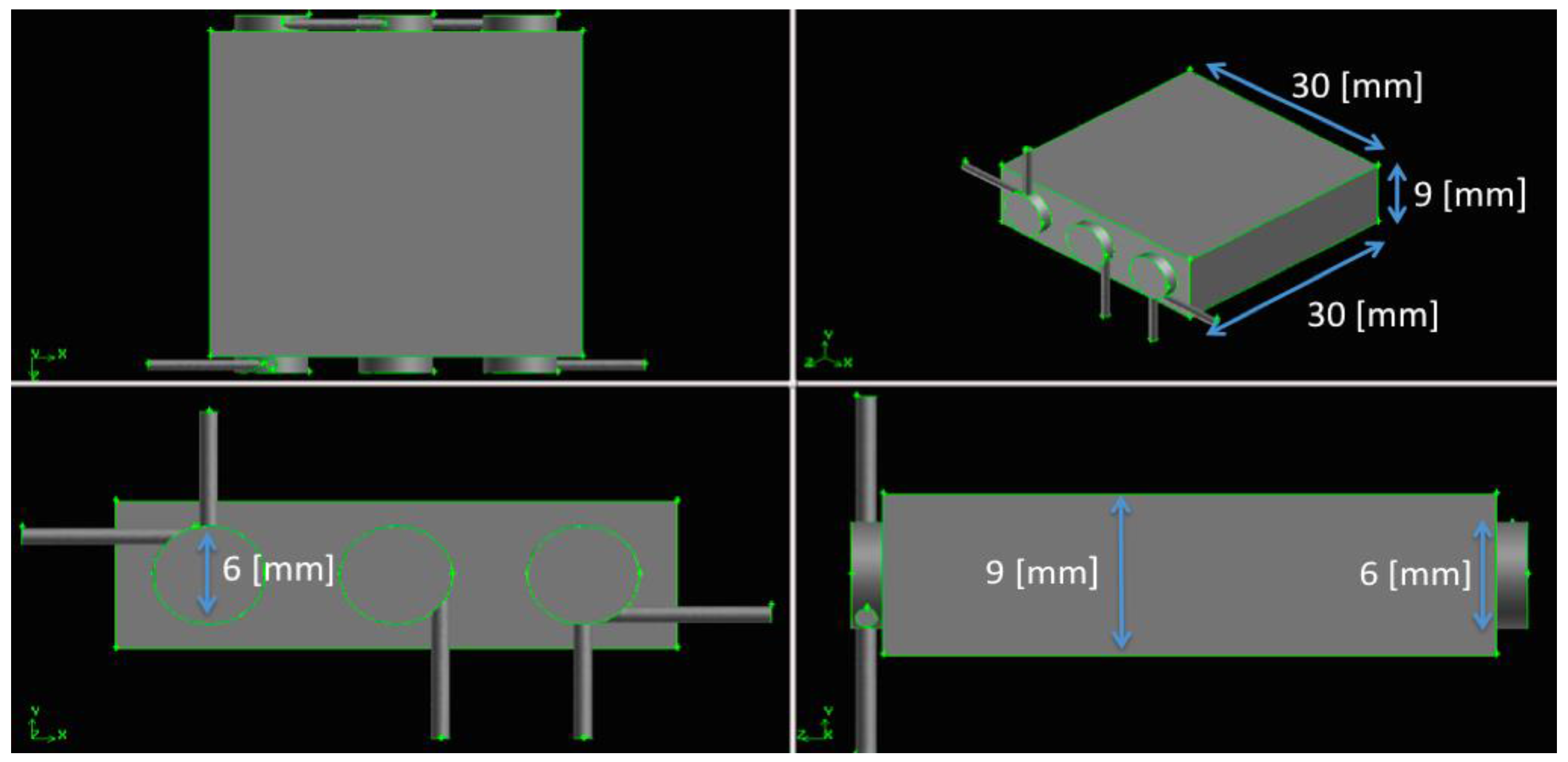
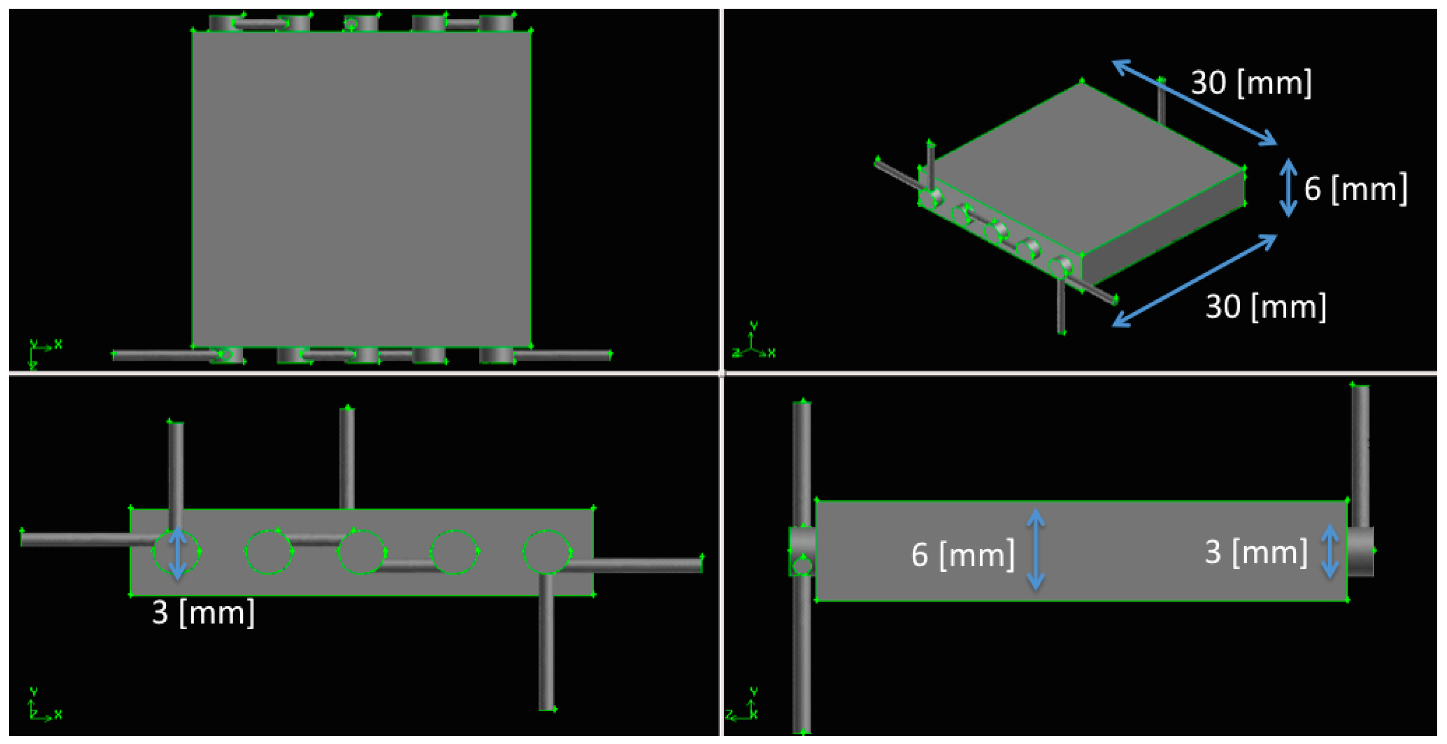
The new configurations are characterized by two, three, and five connected swirling combustion chambers, inside the emitting parallelepiped element; see
Figure 2,
Figure 3,
Figure 4 and
Figure 5, for the geometrical configuration and the relative overall dimensions.
The combustion chambers, adopted in the three configurations, differ for their diameters (3-6-11 mm) while the axial length is fixed to 33 mm. Consequently, they are characterized by different aspect ratios (Z/D = 11-5-3) and by different total combustion volumes (about 1166-2798-6269 mm
3). The converters have
x-
z fixed dimensions (30 × 30 mm
2), while the thickness (
y-dimension) is always 3 mm greater than the diameter, then 6-9-14 mm; the relative distance between the chambers is 4-4-3 mm. These geometrical characteristics are reported in the following
Table 1.
The Z/D = 5-11 configurations present two fuel inlet ducts and one outlet duct, while the Z/D = 3 presents only one fuel inlet duct. The connections, among the chambers, permit to increase the overall residence time (it increases the total available volume) and to balance the cold and hot points on the emitting surfaces.
These three configurations have been analyzed,
in primis, by means of solar mode simulations (see
Section 3) and, the ones that fulfill the thermal resistance efficiency requirement (η
TR ≥ 20%), are investigated adopting reactive Navier-Stokes simulations (see
Section 4 for numerical details and results).
3. Solar Mode Simulations
A Fourier parametric analysis has been carried out to mimic the solar mode operation to understand the effects of the dimensions of the chambers’ diameters, inside the converter, on the converter’s thermal conductivity and, consequently, on the final TPV energy conversion.
As previously described, the three configurations differ in the chamber diameters, in their number and then in the converter’s thickness. Solar mode simulations are carried out imposing a thermal flux of about 500 W on the “wall 1” (“wall 1” is the surface that faces the sun, see
Figure 5).
This value is reached by defining an external radiative source, which mimics the sun, at a temperature of about 2600 K.
The walls are emitting surfaces, according to the emissivity values reported in
Figure 5.
The walls are characterized by a convective coefficient H = 12 W/(m2 × K), calculated at standard and rest conditions. Chamber walls are thermally conductive, while inlet and exhaust ducts walls are adiabatic (to mimic a material with insulating properties).
The parallelepiped is modeled adopting the following material properties:
- -
Density, ρ = 3100 kg/m3;
- -
Specific heat at constant pressure, Cp = 600 J/(kg × K); and
- -
Thermal conductivity, according to the polynomial reported in [
6].
Investigations have been carried out analyzing the thermal resistance efficiency according to the following Equation (1):
Results are reported in the following
Table 2.
The solar mode investigation indicates that the Z/D = 3 configuration (two chambers; 11 mm in diameter; 14 mm of total thickness) exceeds the 20% thermal resistance efficiency limit, while the Z/D = 5 and Z/D = 11 configurations (respectively, three chambers; 6 mm of diameter; 9 mm of total thickness, and five chambers; 3 mm of diameter; 6 mm of total thickness) fulfill the thermal resistance efficiency constraint, even though the Z/D = 5 is at the limit.
Figure 6 and
Figure 7 report the thermal maps in the solar mode operation for the Z/D = 5-11 configurations.
In light of the previous results, combustion simulations are carried out only for the Z/D = 11 and Z/D = 5 configurations; see the following
Section 4.
4. Combustion Mode Simulations
In this section the reactive Navier-Stokes numerical simulations are reported. The aim is to obtain the maximum peak temperature, the smallest ΔT, and the maximum thermal power, delivered to the environment, from the emitting wall that faces the TPV.
In particular, section 4.1 describes the operating conditions,
Section 4.2 the numerical modeling, and
Section 4.3 the results.
4.1. Operating Conditions
Investigations are carried out assuming 500 W of injected thermal power at stoichiometric conditions and adopting inlet temperature equal to 450 K, to mimic pre-heating at stationary conditions. The inlet mass flows and the relative Reynolds numbers are shown in
Table 3.
The inlet Reynolds numbers, respectively laminar and turbulent for the fuel and air inlets, impose deeper investigations to understand whether the flow is fully turbulent or not (Reynolds numbers are based on the 1 mm orifice diameter); laminar and moderately turbulent flow regimes are a typical feature of micro-meso combustor [
7].
The regime depends on temperature (viscosity increases with the root of the temperature), on the expansion effects inside the chamber and on the complex fluid dynamics that characterizes these small devices (swirling and recirculation motions).
These considerations explain the fact that laminar zones may locally exist together with turbulent zones and
vice versa, introducing the issue of which approach should be chosen to solve the reactive Navier-Stokes equations; see
Section 4.2 and
Section 4.3 for further details.
The swirl number (
Sw) is the result of the air-fuel injections parameters and geometry; it is defined as the axial flux of the swirling momentum divided by the axial flux of the axial momentum (see Equation (2)):
The surface integral is calculated at the
Z = 0.03 m height, immediately downward of the inlet plane (
Sw values, at reacting conditions, are reported in
Section 4.3).
4.2. Numerical Modeling
The grid sensitivity analysis, reported in [
1], indicated that a circumferential distance between gridpoints of 0.2 mm, on the chambers, and of 1 mm, on the walls of the brick, is the optimum. The meshes, adopted in the present study, have a total number of cells respectively equal to about 1.4 M (5 chambers)–2.2 M (3 chambers). The grid analysis carried out at cold conditions is assumed suitable for the reacting case as well; this is because greater levels of turbulence, and then greater gradients, characterize cold conditions with respect to the same case at reacting conditions and, moreover, combustion is modeled by the EDC confirming the fact that it is the turbulence the focal issue
After this, “reordering, smoothing, and swapping” techniques were adopted for the three meshes in order to speed up calculations and increase mesh quality. In particular, reordering (the reverse Cuthill-Mckee method [
8]) was adopted to reduce the bandwidth of the cell neighbor number, in order to speed up the calculations, while “smoothing and swapping” were used, respectively, to reposition nodes (by lowering the maximum skewness of the grid) and to modify the cell connectivity.
The latter technique produces a constrained Delaunay mesh [
9] in which the minimum angles in the mesh are maximized, tending toward equilateral cells, providing the “most equilateral” grid for the given node distribution.
The first point near the wall is at y+ < 3 and Δy+ < 1, for all of the configurations (only a few points, in the air inlet ducts where velocities are higher, are close to y+ ~ 15). This means that the first point away from the wall is inside the viscous sublayer.
As previously mentioned, laminar zones may coexist with turbulent ones inside micro-meso combustors. This poses the problem of which numerical model is the most reliable to treat this physical peculiarity.
A pure laminar approach would be unable to predict turbulent field zones, of crucial importance when reactions are present, while turbulent models would over-predict transport wherever the actual regime was laminar.
Fluid dynamics have been solved adopting the RANS k-eps turbulence approach, with the enhanced wall treatment [
10].
This model has been chosen for its ability to reproduce laminar dynamics and for the fact that it solves the eps-unknown, which is present in the definition of the Kolmogorov scales, .
The Kolmogorov scale provides an indication of the actual flow regime and permits understanding the feasibility of a direct numerical simulation (DNS) inside the chamber.
The specific heat at constant pressure, C
pi, is fitted by polynomials of temperature from the GRIMech Thermo Data file [
11], properly introduced in the CFD code, while viscosity and thermal conductivity, μ and k, are predicted by the gas kinetic theory [
12]; mixtures are composition-dependent according to Wilke’s formula [
13].
The turbulence-combustion coupling is modeled adopting the eddy dissipation concept (EDC) [
14,
15], while the hydrogen/air kinetics are modeled with a detailed mechanism of nine species and 21 reactions [
16].
The reactive Navier–Stokes equations were solved adopting a finite-volume solver (Ansys 14 CFD code). The computing resources, and the eventual related technical support, used for this work, is part of the CRESCO/ENEAGRID High Performance Computing infrastructure and its staff [
17]. CRESCO/ENEAGRID High Performance Computing infrastructure is funded by ENEA, the Italian National Agency for New Technologies, Energy, and Sustainable Economic Development, and by Italian and European research programs [
18].
The simulations were carried out adopting the pressure-based version of the solver, assuming the PISO scheme [
19,
20] to solve the pressure-velocity coupling and the third-order MUSCL scheme [
21] for the spatial discretization of all the variables. Further investigations could also consider higher-order discretization algorithms, such as MUSCL fifth-order, WENO fifth-order, and/or WENO ninth-order [
22], in particular with the LES or DNS approach.
4.3. Results and Discussion
In the literature, a numeric-experiment comparison related to swirling combustion chambers [
9] is available. That investigation assumes methane with 123 W of injected thermal power, one swirling chamber (6 × 9 mm
2), 3 atm of operating pressure, and no fluid-structure interaction. Results confirmed a great correspondence between numerical and experimental combustion efficiency (84%–85%), confirming that the overall approach is correct.
In order to facilitate the discussion, the outcomes of the two final configurations (Z/D = 5-11) are reported in the following
Table 4 and
Table 5. They provide the available volume, the combustion efficiency (Equation (3)), the average temperature at the exhaust section, the swirling number at reacting conditions (Equation (2), calculated at Z = 30 mm), the maximum temperature, the minimum temperature, the average temperature, the standard deviation and, finally, the external heat transfer; these data are provided both for “wall 1” and “wall 3”.
The iterative solution was assumed converged when the difference between the inlet and outlet mass flow rates, Δ
m/Δ
t, was at least two orders of magnitude smaller than the smallest flow rate at the inlet section (that is, the hydrogen injection).
The combustion efficiency data, reported in
Table 4, indicate that the chemical efficiency is high for both of the configurations. In fact, the H
2 chemistry is fast enough to have complete combustion (chemical efficiency greater than 99%), even for the Z/D = 11 configuration (diameter equal to 3 mm).
The swirling number, Sw, correctly increases with the diameter, due to the decreased curvature, and then to the increased tangential velocity; this surely affects the “pushing effect” of the fresh reactants against the internal chamber wall, improving the thermal protection effect and increasing the residence time and the mixing.
The Z/D = 11 configuration provides greater thermal power to the ambient environment from both the walls; in fact, the maximum temperatures, the minimum temperatures, and the average ones, are greater than the respective ones obtained with the Z/D = 5 configuration.
This result is confirmed by the standard deviation that, in the Z/D = 11 configuration, is about half of that in the Z/D = 5 configuration.
Both of the configurations fulfill the required performance (Tpeak emitting surface > 1000 K and ∆Temitting surface < 100 K). In fact, the Z/D = 11 (Z/D = 5) configurations reach, from the emitting surfaces “wall 3”, a peak temperature value equal to 1390 K (1346 K) and the ∆T = 45 K (∆T = 75 K). These performances indicate that both of the configurations are compatible with a thermal/electrical conversion by thermo-photovoltaic cells.
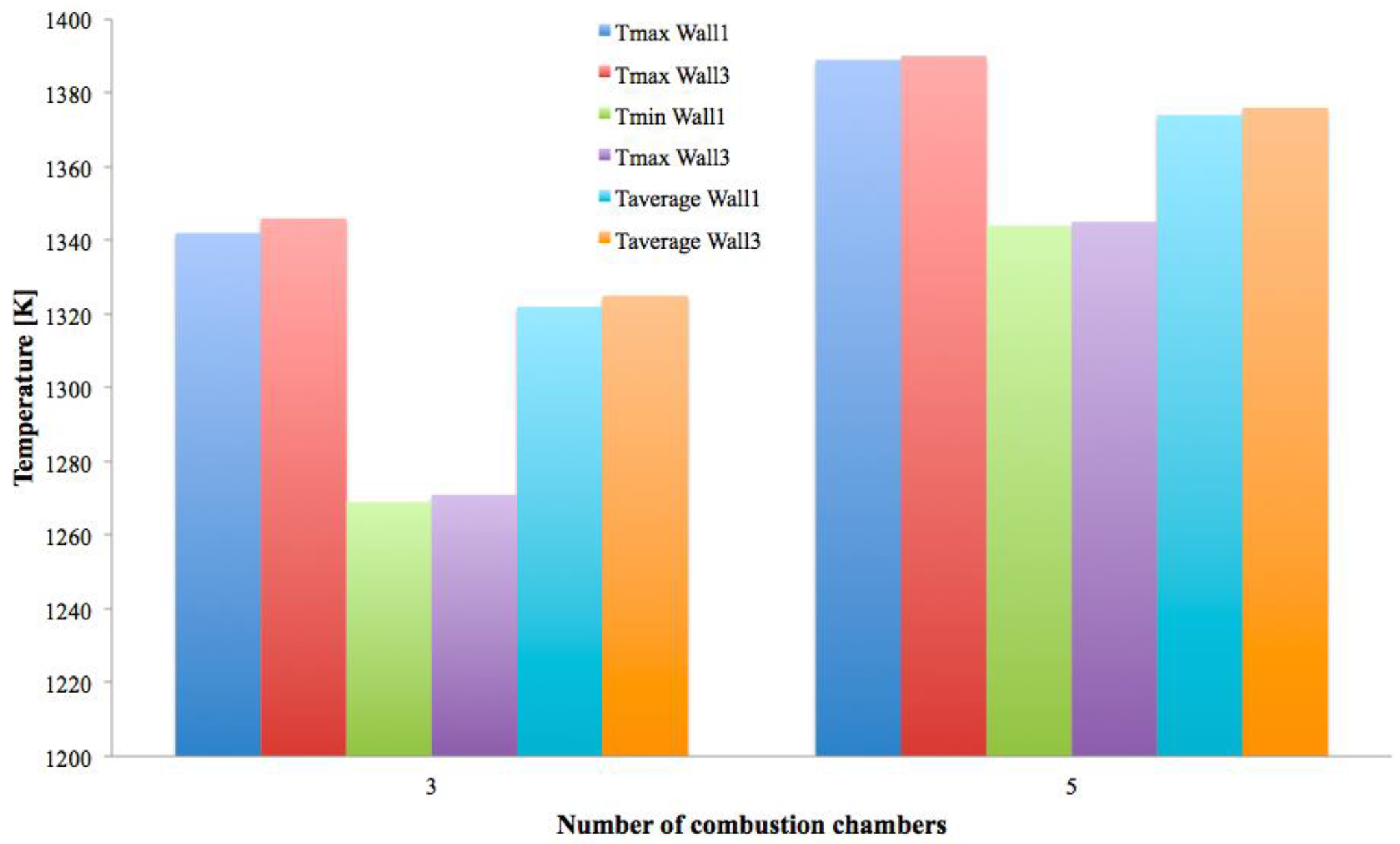
Figure 8 reports the power delivered to the ambient from “wall 1” and “wall 3”,
Figure 9 reports the maximum, minimum, and the average temperature on “wall 1” and “wall 3”, while
Figure 10 reports the standard deviation, σ
T, of “wall 1” and “wall 3” (the results are provided as a function of the number of chambers inside the converter, which is inversely proportional to the chambers diameter dimension, to the total thickness and, finally, to the Z/D aspect ratio).
As in [
1], this work confirms that defining a single regime inside the chamber would be incorrect, because the Kolmogorov scale, see
Figure 11, identifies weak turbulence zones (in the air inlet ducts and in the first zones of the chambers) together with laminar ones (fuel inlets and inside the chambers).
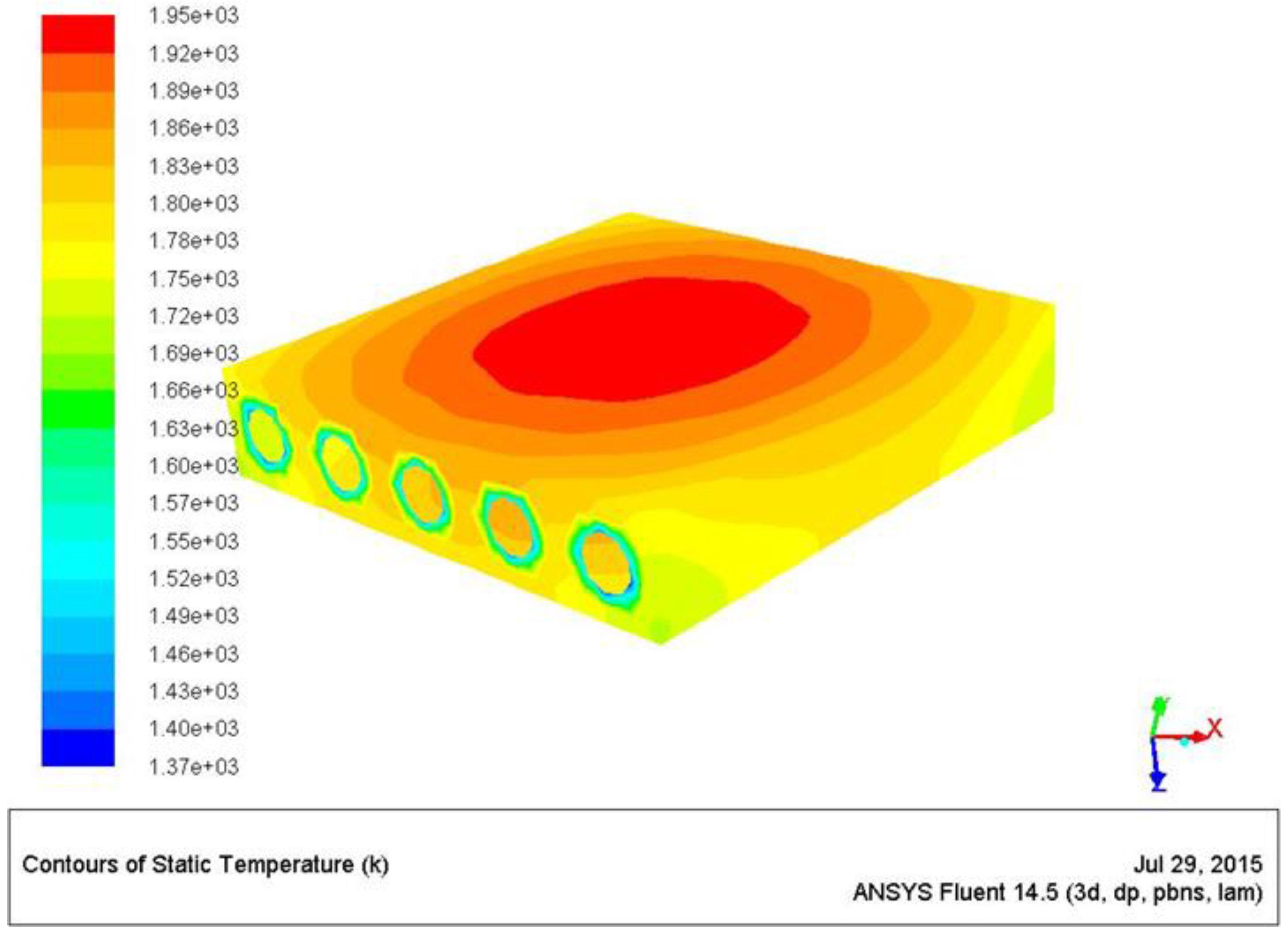
Figure 12 presents the temperature map on the walls of the combustion. The effects of the two different wall boundary conditions (the adiabatic wall, at the inlet and outlet sections, and the conductive walls in the central part of the chambers) are evident.
Figure 13 reports the temperature map on the meridian x-z plane, which cuts the converter. It shows the fluid dynamic inside the chamber and the heat transfer from the chambers to the external emitting walls, due to the conductive Si-C material.
A burning central zone, where temperature peaks, and a colder zone, close to the wall, are predicted. The centrifugal force, due to the imposed swirling motion, “pushes” fresh reactants toward the wall. This forced stratification naturally protects the wall from the high gas temperature.
Figure 14 reports the temperature map of the emitting surfaces from which it is evident how the configuration with five chambers (Z/D = 11) performs better in terms of ∆T. In fact, this configuration figures out an external maximum temperature of 1390 K, and a delta of 45 K, compared to the Z/D = 5 configuration that predicts a maximum temperature of 1346 K and a delta of 75 K (see
Table 5).
Figure 15 provides the overpressure map and shows that an inlet overpressure of about 3 atm, at steady state conditions, is required for both the configurations (the exhaust section is at ambient conditions,
P = 1 atm). This result differs from what is reported in [
1], where the simulation of two “not-connected” chambers, at the same exhaust pressure conditions, predicts a slight overpressure.
Figure 16 shows the negative
Z-velocity maps along the
XZ-plane inside the chambers. It shows the recirculation bubbles along the three and five chambers. It is evident how the bubbles are wider in the Z/D = 5 configuration than in Z/D = 11 one. They work as flame holders and are fundamental for mixing, assuring high chemical efficiencies (values are reported in
Table 4).
5. Conclusions
This work focuses on the performance of an energy converter characterized by a parallelepiped block of emitting material with internal two, three, and five connected swirling micro-meso chambers, fed by H2/air.
These configurations assume identical injected thermal power (500 W) and equivalence ratio (Phi = 1), but differ for the diameter-length ratio, Z/D.
The goal of the work is to define a converter configuration which fulfills, simultaneously, four design requirements: emitting surface area of 30 × 30 mm2; a thermal resistance efficiency, during the solar mode, greater than 20%; a peak temperature greater than 1000 K; and the delta temperature on the emitting surface less than 100 K.
These requirements impose, in primis, Fourier investigations, to mimic the solar mode operation, and then reactive Navier-Stokes simulations, to reproduce the combustion mode operation.
The Fourier investigation provides that:
- (1)
The converter must not exceed a total thickness of 9 mm; and
- (2)
The five and three connected chambers (Z/D = 11-3 mm of diameter and Z/D = 5-6 mm of diameter) are the final configurations.
After this, these two configurations are analyzed by means of combustion simulations.
The most important outcomes are:
- (1)
Both the configurations provide complete combustion;
- (2)
The H2 chemistry and the great residence time, further increased by the recirculation bubbles due to the swirling movement, are not sensitive to the different geometrical configurations;
- (3)
The Z/D = 11 performs much better than the Z/D = 5 configuration in terms of ∆T and thermal resistance efficiency;
- (4)
The counter flows, inside the five combustion chambers, balance the hot-cold points, on the parallelepiped walls, much better than the Z/D = 5 configuration; and
- (5)
The Z/D = 11 configuration is characterized by a more homogenous emitting surface temperature (standard deviation equal to 8 instead of 15) and by a lower surface ∆T (45 K instead of 75 K).
Further improvements might be focused both on numerical and technological issues.
For example, numerically, LES or DNS investigations seem feasible due to the low turbulence levels, at least inside the chambers, while, technologically, cluster configurations and/or connections to micro-turbine, might be analyzed to study the effects on the energy efficiency. In fact, the present results indicate that the temperature at the exhaust section might be compatible with the material requirements at the inlet section of a micro-turbine.


