Article

An Experimental Study of Pile-Supported OWC-Type Breakwaters: Energy Extraction and Vortex-Induced Energy Loss

1
Ocean College, Zhejiang University, Hangzhou 310058, China
2
Department of Ocean and Resources Engineering, School of Ocean and Earth Science and Technology, University of Hawaii at Manoa, Honolulu, HI 96822, USA
*
Author to whom correspondence should be addressed.
Energies 2016, 9(7), 540; https://doi.org/10.3390/en9070540
Submission received: 12 April 2016 / Revised: 20 June 2016 / Accepted: 9 July 2016 / Published: 13 July 2016

Abstract

:
Integrating wave energy converters with breakwaters is a promising concept for wave energy utilization. On the basis of fulfilling the wave protection demands, pile-supported Oscillating Water Column (OWC)-type breakwaters can also meet the local needs of electricity far from the lands. In the present study, the wave energy extraction and vortex-induced energy loss of pile-supported OWC-type breakwaters were analyzed based on a two-point measurement method. The importance of energy extraction and vortex-induced energy loss on the wave energy dissipation of pile-supported OWC-type breakwaters were experimentally investigated. It was found that the trends of energy extraction and vortex-induced energy loss were generally correlated. The effects of the pneumatic damping induced by top opening affected the vortex-induced energy loss more than the energy extraction. Results showed that a larger pneumatic damping was preferable for the purpose of increasing energy extraction, whereas for a smaller pneumatic damping the vortex-induced energy loss was more important to the energy dissipation. With increasing draft, the energy extraction decreased, but the vortex-induced energy loss complementally contributed to the total energy dissipation and made the energy dissipation at the same level as that for a shallower draft.

Graphical Abstract

1. Introduction

Recently, pile-supported breakwaters have been a rising choice for protecting marine structures and activities against wave attack in relatively deep water. This type of breakwater is environmentally friendly since it permits water exchange and sediment transport underneath. Meanwhile, this type of breakwater is also economically competitive since its construction costs are insensitive to the water depth. However, different from traditional bottom-sitting breakwaters that can intercept all incoming waves, pile-supported breakwaters can only provide a limited wave protection. Interacting with pile-supported breakwaters, the incoming wave energy is partially reflected, partially transmitted underneath the breakwater and partially dissipated. The relative breadth and relative draft are two key parameters determining the wave protection performance and construction cost of pile-supported breakwaters.
The simple configurations of pile-supported breakwaters such as a vertical plate or a rectangular box reduce the wave transmission mainly through the mechanisms of wave reflection, thus the wave force on the structure is large and the wave protection is weak. For a better performance, many novel configurations of pile-supported breakwaters have been proposed mainly based on the mechanisms of energy dissipation, such as double slotted barriers [1], T-type [2], absorbing perforated-wall breakwaters [3], multiple-layer plates [4], horizontal twin plates [5], semicircular perforated plate [6], horizontal twin porous plates [7], multiple-layer arc plates [8], etc. These novel configurations aim at dissipating more wave energy through such mechanisms such as vortex shedding, generation of turbulence, or/and wave breaking. Distinguished from other novel pile-supported breakwaters, He and Huang [9] made use of a pile-supported oscillating water column (OWC) structure as a breakwater. While other breakwaters dissipate wave energy only into unusable forms, OWC-type breakwaters also extract part of wave energy for electricity generation.
The OWC structure is one of the most studied wave energy converters. A typical OWC structure consists of a pneumatic chamber with a large opening below the water level and a turbine installed on the top cover. The incoming waves cause the water column inside the chamber to oscillate through the large bottom opening; air trapped above the water surface inside the chamber is pressured by the oscillation of water column and can exit the chamber through the turbine. In a laboratory setting, the turbine is usually modeled by an orifice in the form of either a small circular opening or a narrow slot opening. As illustrated in Figure 1, an OWC structure can dissipate wave energy through two sources: the airflow through the small top opening (energy extraction) and the vortex shedding at the edges of the large bottom opening (vortex-induced energy loss). The operating principle and structural configuration of OWC structure make it very suitable for integrating with caisson breakwaters. In the 1980s, Ojima et al. [10] advocated the OWC-type breakwater. Afterward, the bottom-sitting OWC caisson breakwaters were studied by Takahashi et al. [11], Thiruvenkatasamy and Neelamani [12], Tseng et al. [13], Boccotti et al. [14], Boccotti [15], etc. In 2011, the first commercial OWC caisson breakwater was successfully implemented at Mutriku, Spain [16]. As the marine developments and activities progress into relatively deep water, pile-supported and floating OWC-type breakwaters begun to be proposed and have been studied by some researchers (e.g., [9,17,18,19,20]). On the basis of fulfilling the wave protection demands, OWC-type breakwaters can also extract wave energy for the local needs of electricity far from the lands. In addition to the OWC-type breakwaters, prototype OWC power plants designed only for wave energy extraction, such as LIMPET OWC in Scotland [21], and PICO OWC in Portugal [22], have also been successfully built.
If the purpose of the OWC structure is to extract wave energy, vortex-induced energy loss is considered detrimental to the energy extraction and should be minimized. However, if the purpose of the OWC structure is to reduce transmitted waves, vortex-induced energy loss is beneficial to the total energy dissipation and can improve the wave protection performance. To date, most of the studies of OWC focus on the energy extraction (e.g., [23,24,25,26,27,28,29]), and there have only been a few earlier studies touching upon the vorticity characteristics of OWC (e.g., [30,31,32]). Analytical and numerical studies based on potential theory are with certain limitation in dealing with viscous effects, while numerical studies based on viscous flow theory need experimental results for validation. However, to the best of the authors’ knowledge, almost no experimental study of OWC structures in the literature reported both the energy extraction and vortex-induced energy loss.
Inside an OWC structure, the instantaneous water surface elevation across the cross section of the pneumatic chamber is spatially variant unless for the limiting case of very long waves [33]. This feature makes the accurate experimental measurement of energy extraction a challenging task. In most of previous OWC experiments, the water surface elevation was measured at only one single point inside the pneumatic chamber (e.g., [12,13,34,35]), which may lead to noticeable errors in the energy extraction measurement. To consider the spatial non-uniformity, He and Huang [36] proposed a two-point measurement method which can reconstruct the instantaneous spatial water surface profile inside the pneumatic chamber, and thus can measure the energy extraction more accurately. Based on this method, the vortex-induced energy loss can be further analyzed through an energy balance.
This study is a follow-up investigation of He and Huang [9], who made use of a pile-supported OWC structure with symmetric front and rear walls as a breakwater. Through experimental investigation, He and Huang [9] demonstrated that the performance of pile-supported OWC-type breakwaters in terms of wave transmission is not inferior to other novel pile-supported breakwaters. For pile-supported OWC-type breakwaters, both energy extraction and vortex-induced energy loss contribute to the energy dissipation, which is essential to the performance of wave protection. But due to the difficulties in measuring the instantaneous water surface elevation inside the pneumatic chamber, energy extraction and vortex-induced energy loss by the OWC structure were not examined in He and Huang [9]. In the present study, a series of wave-flume experiments under same test conditions of He and Huang [9] was carried out. The wave energy extraction and vortex-induced energy loss were analyzed based on the method proposed by He and Huang [36]. The effects of relative chamber breadth, chamber draft and top opening characteristics on the energy extraction of pile-supported OWC-type breakwater were investigated. Meanwhile, the importance of energy extraction and vortex-induced energy loss to the total wave energy dissipation at the OWC structure was also studied. The objective of this study is to understand the wave energy dissipation mechanisms of pile-supported OWC-type breakwaters and provide a set of experimental data for validation of numerical models developed for OWC structures.

2. Experiments

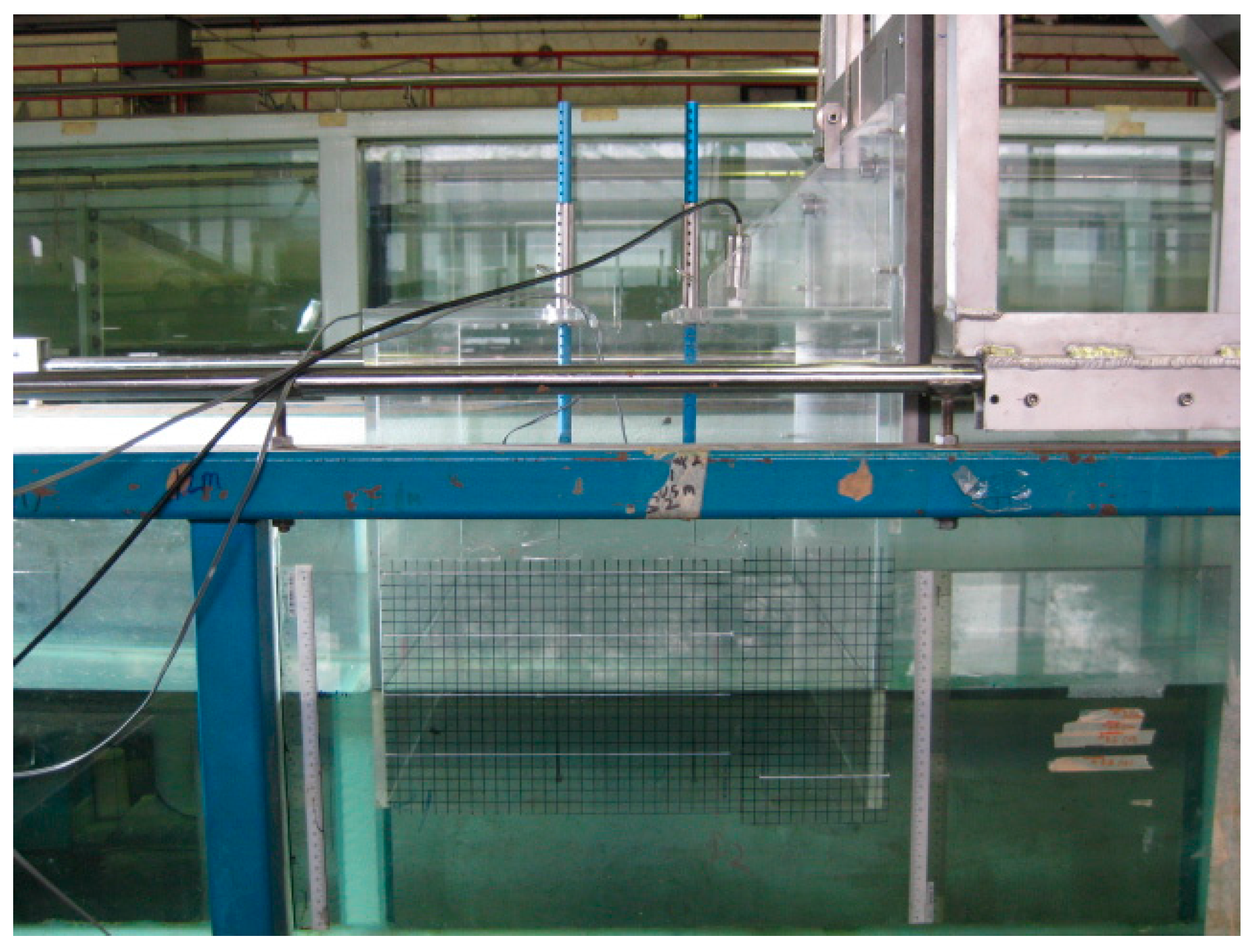
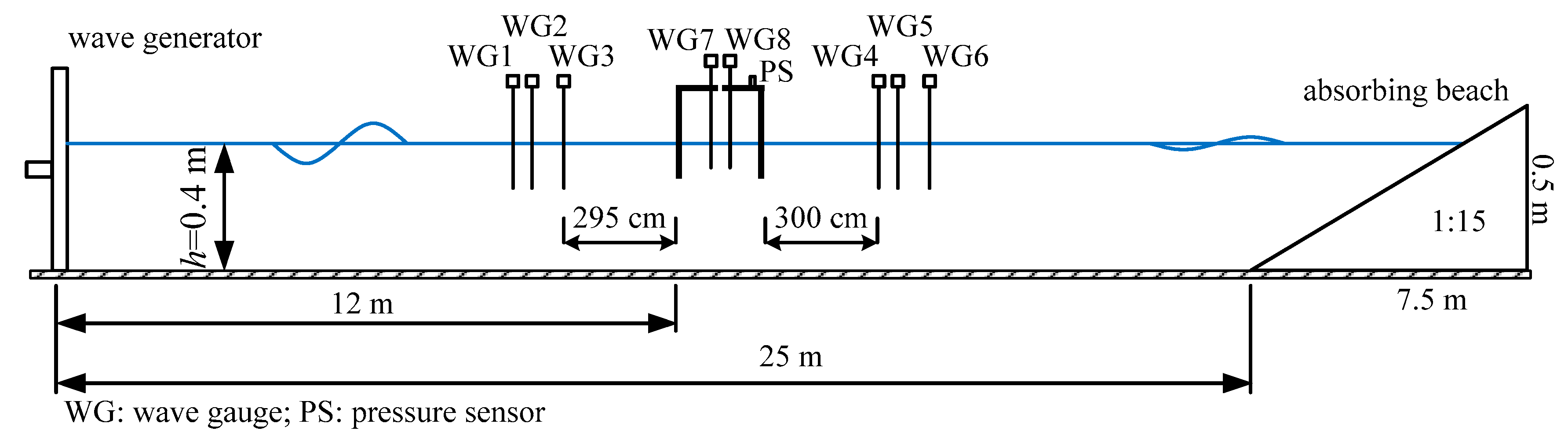
2.1. Experimental Setup and Test Procedures

The experiments were carried out in a glass-walled wave flume at the Hydraulics Modeling Laboratory, Nanyang Technological University, Singapore. The dimensions of the wave flume were 32.5 m long, 0.55 m wide and 0.6 m deep. A piston-type wave generator was installed at one end of the flume, and a wave-absorbing beach was located at the other end of the flume for reducing wave reflection. The beach slope was 1:15 and covered with porous mats. The wave reflection coefficients of the absorbing beach were kept as lower than 0.05 for all test conditions in the present study.
Figure 2 shows a photo of the OWC model tested in this study, which was made of 10-mm thick Perspex sheets. The model was a suspended rectangular hollow chamber with symmetric front and rear walls, and was designed to span across the width of wave flume. The interior dimensions of the chamber were 530 mm in length, 400 mm in breadth, and 400 mm in height. The model was attached to a fixture firmly mounted on the flume. The draft of the model can be flexibly adjusted to a particular value and then locked. Three drafts (0.1 m, 0.15 m, and 0.2 m) were examined in this study.
A small opening in the top cover of the pneumatic chamber was used to simulate the power take-off mechanism. In the present study, to examine the effects of top opening characteristics, two opening shapes (slot and circular) and three opening ratios (0.625%, 1.25%, and 1.875%) were tested. Table 1 summarizes the geometric parameters of the top opening tested in this study.
A sketch of the experimental setup is shown in Figure 3. The OWC breakwater model was placed at the middle section of wave flume, which was 12 m away from the wave generator. A total of eight resistance-type wave gauges of 0.1 mm resolution were used to measure the instantaneous water surface elevations: three (WG1–WG3) were placed on the seaward side of the model for the separation of incident waves from reflected waves, three (WG4–WG6) were placed on the leeward side of the model for the separation of transmitted waves from the waves reflected from the wave-absorbing beach, and the other two (WG7 and WG8) were placed inside the pneumatic chamber for reconstructing the water surface inside the chamber. For more details about the water surface reconstruction inside the chamber, interested reader is referred to He and Huang [36], who reconstructed the water surface elevation with the same method and validated with the synchronous snapshots of video recordings.
Same as the test conditions in He and Huang [9], a series of experiments was conducted under regular wave conditions. The water depth was fixed at 0.4 m, and the target wave height was set at 0.035 m in the experiments. The wave periods varied from 0.9 to 1.6 s at a 0.1 s interval. The wave length ranged from 1.22 to 2.84 m. Thus, the relative model breadth ranged from 0.141 to 0.328, and the wave steepness ranged from 0.0123 to 0.0287. For an OWC structure, the sloshing mode will occur at B/L = 0.5 [33,37]. At sloshing mode, a standing wave pattern inside the chamber will happen and result in a nearly zero air pressure fluctuation. Meanwhile, a large relative breadth B/L > 0.5 will make the structure costs high. Therefore, we are only interested in the range of B/L which is far lower than 0.5 in this study. Details of the test conditions are summarized in Table 2.
For a scale factor of 25 based on Froude similarity, the breadth of prototype OWC structure is 10 m, the water depth is 10 m, the incident wave height is 0.875 m and the prototype wave period ranges from 4.5 to 8.0 s.

2.2. Data Analysis

The heights of incident waves ( H i ), reflected waves ( H r ) and transmitted waves ( H t ) are obtained through the two-point wave separation method proposed by Goda and Suzuki [38]. Different distances among three wave gauges either on the seaward side or leeward side provide several sets of data available for wave separation. The reflection coefficient ( C r ) and transmission coefficient ( C t ) are defined as
C r = H r H i
and
C t = H t H i
respectively.
The square of reflection coefficient C r 2 represents the ratio of the reflected wave energy to the incident wave energy, and similarly, the square of transmission coefficient C t 2 represents the ratio of the transmitted wave energy to the incident wave energy. Through the wave energy conservation, a dissipation coefficient C d is defined as:
C d = 1 C r 2 C t 2
representing the ratio of the dissipated wave energy to the incident wave energy. We stress here again that the wave energy dissipation comes from two sources: energy extraction and vortex-induced energy loss.
The incident wave power per crest width unit is:
P i ¯ = 1 16 ρ g H i 2 ω k ( 1 + 2 k h sinh 2 k h )
where ρ is the water density, g the gravitational acceleration, ω the wave angular frequency, k the wave number, and h the water depth. For energy extraction, the period-averaged power extracted by the OWC structure per width unit is:
P ¯ o = B T t 0 t 0 + T p ( t ) u ¯ ( t ) d t
where B is the OWC chamber breadth, T the wave period, p ( t ) the instantaneous air pressure inside the chamber, and u ¯ ( t ) the instantaneous spatially-averaged water surface velocity inside the chamber. Thus, the energy extraction efficiency can be calculated as:
ε = P o ¯ P i ¯
Through an energy balance, a vortex-induced energy loss coefficient can be defined as:
C v = C d ε
representing the ratio of wave energy dissipated by the vortex shedding to the incident wave energy.
For a pile-supported OWC-type breakwater, the reflected wave height H r , transmitted wave height H t and period-averaged power extraction P ¯ o related to the air pressure and water surface elevation inside the chamber are mainly affected by the following parameters: the OWC chamber breadth B, the OWC chamber draft D r , the opening characteristics χ (including factors such as opening ratio, opening size and opening shape), the wave length L, the water depth h, the incident wave height H i , the water density ρ and the gravitational acceleration g. Therefore, the performance of OWC can be formally described by the following functional relations:
H r , H t , P ¯ o = f ( B , D r , χ , L , h , H i , ρ , g )
A dimensional analysis through π theorem gives the following dimensionless relationships:
C r , C t , ε = f ( B / L , D r / h , χ , H i / h , B / h )
The relative breadth B/L and relative draft D r / h are two key parameters determining the wave protection performance and construction cost of pile-supported breakwaters. Meanwhile, the chamber parameters B/L and D r / h , and the opening characteristics χ are considered as the most important parameters affecting the performance of OWC structures. Accordingly, the effects of B/L, D r / h and χ on the energy extraction ε and vortex-induced energy loss C v of pile-supported OWC-type breakwater were investigated in the present study. H i / h was kept as 0.0875 and B/L was kept as 1 in the experiments.

3. Results and Discussion

3.1. Energy Extraction

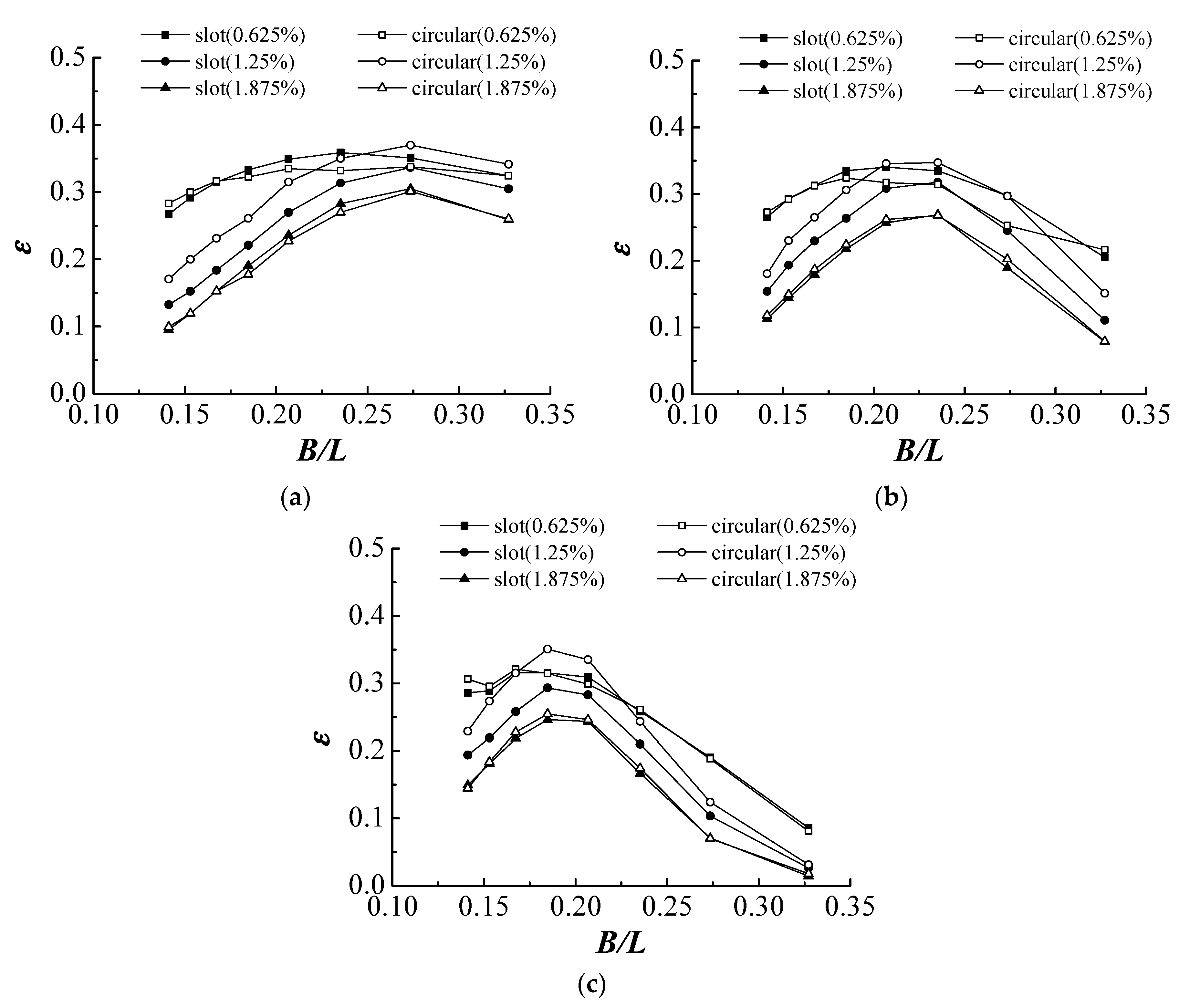
3.1.1. The Effects of Opening Characteristics

Figure 4 shows the variations of energy efficiency ε versus B/L for the six tested top openings with 10, 15, and 20 cm drafts, respectively. Sarmento [39] indicated that the theoretical maximum energy extraction efficiency was 0.5 based on potential theory. However, this theoretical maximum energy extraction efficiency is always not achievable due to the viscous effects. As an illustration, let us examine Figure 4a for the 10 cm draft condition. A local peak ε can be found for each top opening; this local peak ε was 0.36 at B/L = 0.235 for the slot-shaped opening of 0.625% ratio, 0.34 at B/L = 0.207 for the circular-shaped opening of 0.625% ratio, 0.34 at B/L = 0.274 for the slot-shaped opening of 1.25% ratio, 0.37 at B/L = 0.274 for the circular-shaped opening of 1.25% ratio, 0.31 at B/L = 0.274 for the slot-shaped opening of 1.875% ratio, and 0.30 at B/L = 0.274 for the circular-shaped opening of 1.875%. Among these results, the overall maximum ε was only 0.37, implying that a considerable loss on energy extraction was suffered due to the fluid viscosity.
Although the chamber parameters (chamber breadth and chamber draft) were the same, the characteristics of top opening affected the energy extraction notably. For the medium opening ratio (1.25%) and the larger opening ratio (1.875%), the resonance occurred at the same wave period (B/L = 0.274), but for a smaller opening ratio (0.625%), the resonance occurred at larger wave periods (B/L = 0.235 for slot shape and B/L = 0.207 for circular shape). With same opening ratio, the distinction of ε between different opening shapes was most noticeable for the medium opening ratio (1.25%). These observations can be explained by the hydraulic characteristics of small top opening as below.
The pressure fluctuation inside the chamber is due to the hydraulic resistance of the top opening to the air flow. For incompressible air, the relationship between pressure and velocity is quadratic when the top opening is sharp-edged. The pressure drop across the top opening can be modeled as:
p ( t ) = ρ a C f 2 | u ¯ ( t ) | u ¯ ( t )
where ρ a is the air density, C f is the quadratic loss coefficient, and u ¯ ( t ) is the instantaneous spatially-averaged water surface velocity inside the chamber. The quadratic loss coefficient C f which represents the pneumatic damping of top opening can be fitted through Equation (10) with the measured p ( t ) and u ¯ ( t ) . We remark that our results showed that effects of opening shape, size, and opening ratio can be represented by a single parameter, the quadratic loss coefficient C f . Figure 5 shows a comparison of the measured pressure data and the fitting curve for the slot-shaped opening of 1.25% ratio and 1.3 s wave period. Table 3 summarizes the fitted values of C f for the six top openings tested in the present study.
The natural frequency of the OWC structure depends on factors such as draft, breadth, damping induced by the opening. Referring to Falnes [40],
ω 0 = g l + l
δ = D o + D w 2 ( l + l )
ω d = ω 0 2 δ 2
where ω 0 is the undamped natural angular frequency of the oscillating water column, g is the acceleration of gravity, l is the still water length (equal to draft) of the water column, l is the added length due to added mass, δ is a damping coefficient, Do is the damping due to the top opening, Dw is the damping of water column, and ωd is the damped natural angular frequency of the oscillating water column. The resonance of oscillation occurred at the damped natural period of water column. In recent studies, Lopez et al. [24] and Ning et al. [37] indicate that opening damping is the most influential parameter affecting the performance of OWC device. Referring to Table 3, it can be found that a smaller opening ratio induced a larger pneumatic damping. A larger pneumatic damping consequently increased the damped natural period. This explained the observation that the resonance occurred at larger wave periods for a smaller opening ratio. For the same opening ratio, the values of Cf for the circular-shaped openings were generally larger than those for the slot-shaped openings of the same opening ratio. It can also be seen from Table 3 that the relative difference in Cf for different opening shapes of same opening ratio was largest for the 1.25% opening ratio. It was essentially the difference in Cf that caused the distinction of energy extraction between different opening shapes of the same opening ratio.
Figure 4 showed that at a given wave period (B/L) and for the same chamber parameters, the pneumatic damping affected the local maximum extraction efficiency ε. Referring to Figure 4a for the 10 cm draft condition as an example: for the shorter waves of B/L = 0.327, it was the circular-shaped opening of 1.25% ratio (Cf = 17,209–17,701) attaining the local maximum ε; for the intermediate waves of B/L = 0.207, it was the slot-shaped opening of 0.625% ratio (Cf = 47,644–56,748) attaining the local maximum ε; and for the longer waves of B/L = 0.141, it was the circular-shaped opening of 0.625% ratio (Cf = 67,034–68,426) attaining the local maximum ε. Generally, a larger Cf can extract wave energy in a wider range of wave period.
For the deeper draft conditions (15 cm and 20 cm), the effects of opening characteristics on the energy extraction have a similar conclusion to that for the 10 cm draft condition. The effects of chamber drafts on the energy extraction will be discussed in the sections below.

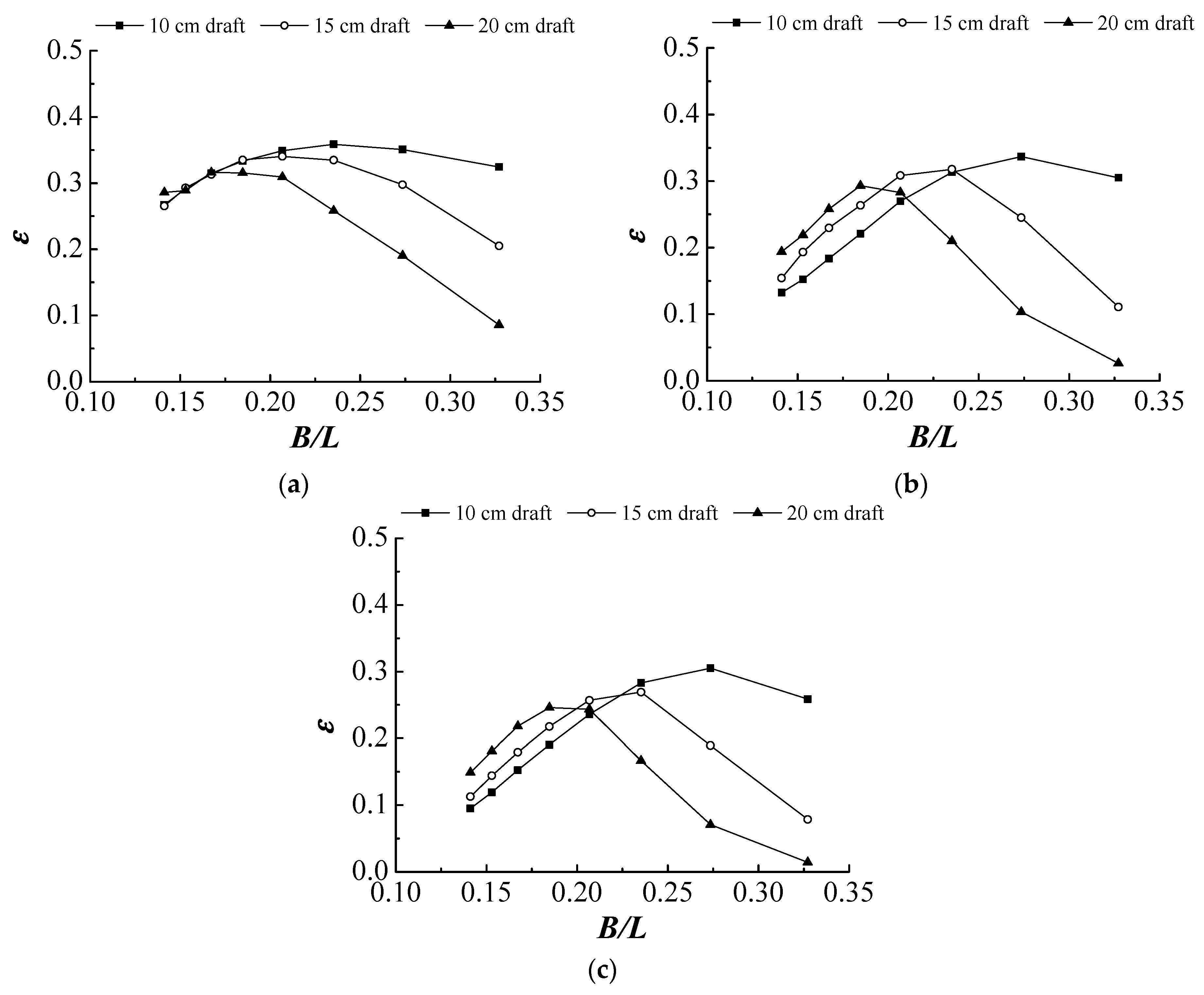
3.1.2. The Effects of Chamber Drafts

Figure 6 shows the variations of energy efficiency ε versus B/L with three tested chamber drafts for three slot-shaped opening ratios. Generally, for all three top opening ratios, increasing the draft increased the wave period at which the resonance of oscillation occurred, but meanwhile diminished the value of peak ε. As an illustration, let us examine Figure 6a for the slot-shaped opening of 0.625% ratio condition; the peak ε of 0.36 was obtained at B/L = 0.235 for the 10 cm draft, 0.34 at B/L = 0.207 for the 15 cm draft, and 0.32 at B/L = 0.167 for the 20 cm draft. This was because that increasing OWC draft can increase the mass of water column inside the chamber, inducing increases in both the inertia effect and natural period. In the tested parameter range, our results showed that a larger pneumatic damping and a shallower draft are beneficial to the overall energy extraction performance.

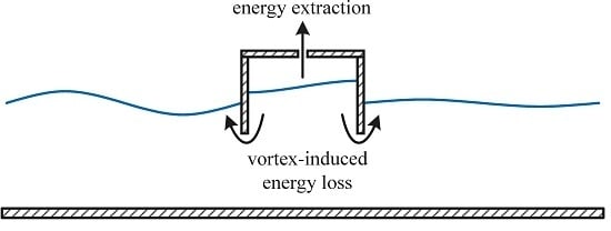
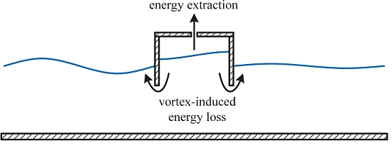
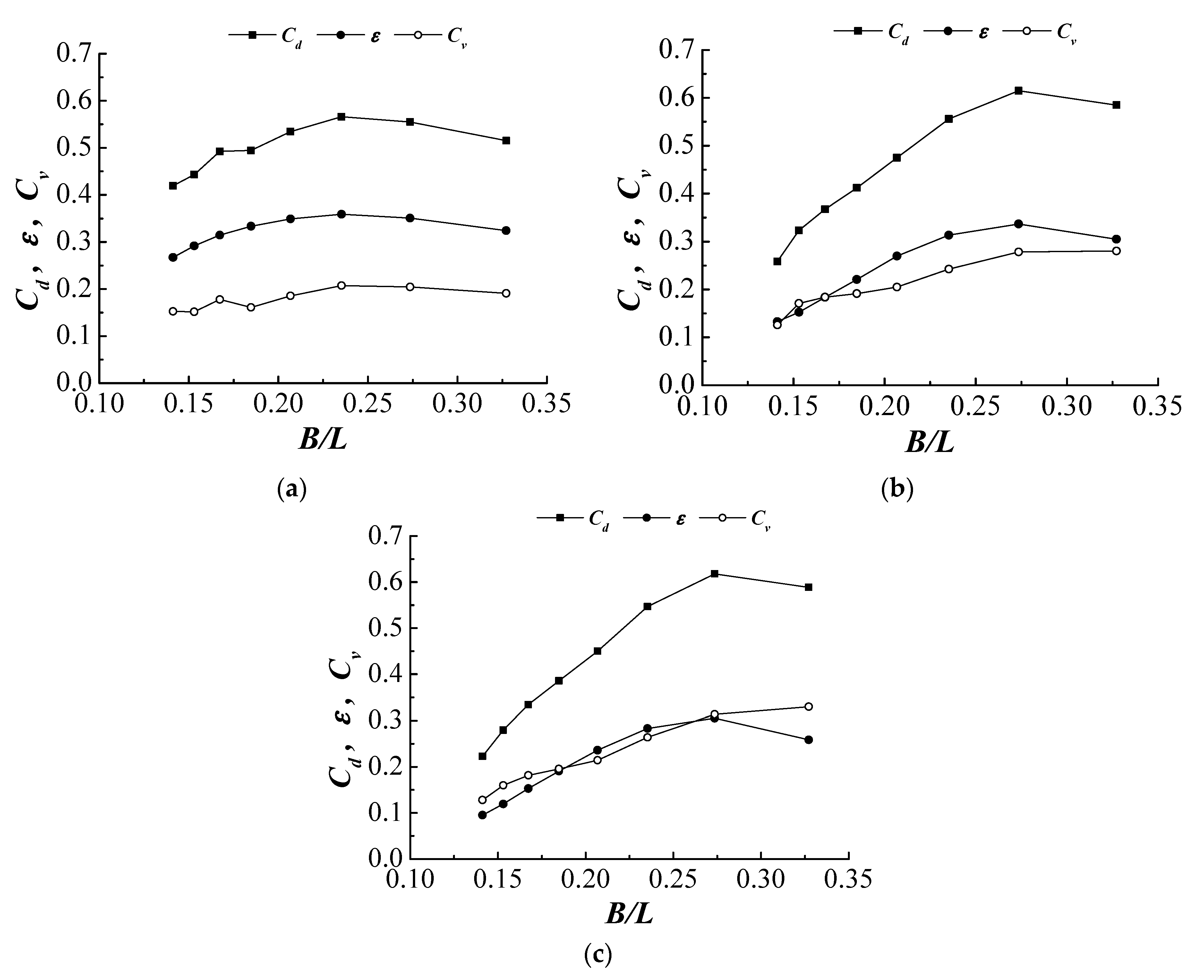
3.2. Vortex-Induced Energy Loss

3.2.1. The Effects of Opening Characteristics

Figure 7 shows the variations of energy dissipation Cd, energy efficiency ε and vortex-induced energy loss Cv versus B/L with 10 cm draft for the slot-shaped opening of 0.625% ratio, of 1.25% ratio and of 1.875% ratio, respectively. It can be concluded that the trends of energy extraction and vortex-induced energy loss were generally correlated. This was because both energy extraction and vortex-induced energy loss were crucially related to the oscillation of water column. With fixed chamber parameters and top opening characteristics, the energy extraction efficiency of an OWC structure was maximized when the resonance of water column oscillation occurred. Meanwhile, at the resonance the violent oscillation inside the chamber accelerated the velocity of fluid passing the lower edges of both front and rear walls of the OWC structure, inducing a large vortex-induced energy loss at the corresponding wave period of resonance. In addition to waves of periods in the vicinity of the damped natural period of water column, a larger vortex-induced energy loss was also prone to happen at shorter waves. Stiassnie et al. [41] studied the vortex-induced energy loss of two vertical plates, which was equivalent to the condition of present model without pneumatic damping effects, and found the vortex-induced energy loss was mainly dependent on the distance between two plates and the draft of the plates in addition to the wave conditions. The vortex-induced energy loss of two vertical plates was reported in He and Huang [9]. For the case where the distance between two plates was 0.4 m and the draft of the plates was 0.1 m, the maximum vortex-induced energy loss Cv occurred at B/L = 0.327. By the joint effects, larger vortex-induced energy loss of the OWC structure can occur in the vicinity of the damped natural period of water column and also at periods of shorter waves.
Comparing Figure 7, the pneumatic damping induced by the top opening affected the relative importance of energy extraction and vortex-induced energy loss remarkably. The values of Cv were much smaller than ε for the slot-shaped opening of 0.625% ratio (Cf = 47,644–56,748), slightly smaller than ε for the slot-shaped opening of 1.25% ratio (Cf = 10,717–12,678), and comparable to ε for the slot-shaped opening of 1.875% ratio (Cf = 5832–6810). A larger pneumatic damping could induce a larger pressure fluctuation inside the chamber but suppress the oscillation of the water column. Since the energy extraction is a collective result of pressure fluctuation and surface oscillation while the vortex-induced energy loss is mainly due to the water column oscillation, the effects of pneumatic damping may affect the vortex-induced energy loss more than the energy extraction. Decreasing pneumatic damping increases the relative importance of vortex-induced energy loss. It can be concluded that a larger pneumatic damping is preferable for the purpose of increasing energy extraction, whereas for a smaller pneumatic damping is preferable for the purpose of increasing the vortex-induced energy loss.

3.2.2. The Effects of Chamber Drafts

Figure 8 shows the variations of energy dissipation Cd, energy efficiency ε and vortex-induced energy loss Cv versus B/L for the slot-shaped opening of 1.25% ratio with 10 cm draft, 15 cm draft and 20 cm draft. It can be seen that the trends of energy extraction and vortex-induced energy loss were still generally correlated for deeper drafts (15 and 20 cm). In the vicinity of the damped natural period of water column where the peak ε occurred, it was interesting to note that the vortex-induced energy loss was affected by the extracted wave energy and was slightly lowered near the resonant period.
With increasing draft, the energy extraction decreased and the importance of vortex-induced energy loss to the energy dissipation increased. The values of Cv were slightly smaller than ε for the 10 cm draft, slightly larger than ε for the 15 cm draft, and much larger than ε for the 20 cm draft. Although the energy extraction decreased with increasing draft, the vortex-induced energy loss complementally contributed to the energy dissipation and made the total energy dissipation at the same level as that of a shallower draft. The peak Cd was 0.61 for the 10 cm draft, 0.63 for the 15 cm draft, and 0.62 for the 20 cm draft.

3.2.3. Remarks

No existing theory allows a direct comparison between the present experimental results with predictions. The established theories of OWC structures reported in the literature were developed based on potential theory, and thus entirely ignored the viscous effects. Representative theories are Evans [42], Sarmento and Falcão [43], and Evans and Porter [33] for an OWC with a rear wall throughout the water depth. The OWC geometries studied in these theories are different from the present geometry, which has symmetric front and rear walls. Although Sarmento [39] studied an OWC with symmetric front and rear walls, the draft was assumed to be zero in his study.
P ¯ o can be calculated in three ways: (i) using measured p ( t ) and u ¯ ( t ) according to Equation (5); (ii) using only measured p ( t ) by replacing u ¯ ( t ) with p ( t ) in Equation (5); and (iii) using only measured u ¯ ( t ) by replacing p ( t ) with u ¯ ( t ) in Equation (5). The last two methods need the knowledge of the quadratic coefficient Cf. However, the characteristics of quadratic loss coefficient Cf were not fully addressed in the literature of OWC. In this study, we determined the value of Cf through a data fitting using the measured p ( t ) and u ¯ ( t ) . As shown in Figure A1 in the appendix, the maximum relative difference between methods (i) and (ii) is 3.7%, and the maximum relative difference between methods (i) and (iii) is 5.2%. The differences are considered from the data fitting of Cf.

4. Conclusions

In the present study, pile-supported OWC-type breakwaters were experimentally investigated. The wave energy extraction and vortex-induced energy loss were analyzed based on the two-point measurement method proposed by He and Huang [36]. The effects of relative chamber breadth, relative chamber draft and top opening characteristics were investigated. The importance of energy extraction and vortex-induced energy loss on the wave energy dissipation of pile-supported OWC-type breakwaters was discussed. The following main conclusions can be drawn from this study.
  • The characteristics of top openings affected the energy extraction notably through the means of opening-induced pneumatic damping. A smaller opening ratio induced a larger pneumatic damping and consequently increased the damped natural period of the OWC structure. It was essentially the difference in pneumatic damping that caused the distinction of energy extraction between different opening shapes of the same opening ratio. A larger pneumatic damping can generally extract wave energy in a wider range of wave period.
  • Increasing chamber draft increased the mass of water column inside the chamber, and thus increased the inertia effect and natural period of the water column. For larger pneumatic damping, a shallower draft can obtain a better overall energy extraction performance.
  • The trends of energy extraction and vortex-induced energy loss were generally correlated because that they were both crucially related to the oscillation of water column. A larger pneumatic damping could induce a larger pressure fluctuation inside the chamber but suppress the surface oscillation of water column, thus the effects of pneumatic damping could affect the vortex-induced energy loss more than the energy extraction. A larger pneumatic damping was preferable for the purpose of increasing energy extraction, whereas, for a smaller pneumatic damping, the vortex-induced energy loss was more important to the energy dissipation.
  • With increasing draft, the energy extraction decreased, but the vortex-induced energy loss complementally contributed to the total energy dissipation; the relative importance of vortex-induced energy loss to the energy dissipation increased with increasing draft and made the energy dissipation at the same level to that of a shallower draft.

Acknowledgments

This work is supported by the Fundamental Research Funds for the Central Universities (Project No. 2016QNA4034).

Author Contributions

Fang He proposed the idea and performed the experiments; Zhenhua Huang provided experimental facilities and measuring tools; Fang He and MingJia Li analyzed the data; MingJia Li and Zhenhua Huang contributed to the discussion of this study; and Fang He and Zhenhua Huang wrote the paper.

Conflicts of Interest

The authors declare no conflict of interest.

Appendix A. Comparison of the Extraction Efficiencies Calculated Using Three Methods

Figure A1 shows an example of values of energy efficiency ε calculated using three methods: (i) measured pressure and velocity; (ii) measured pressure alone; and (iii) measured velocity alone. In this example, the test conditions are: slot-shaped opening ratio = 0.625% and draft = 10 cm. The values obtained using method (i) are regarded as more accurate than those obtained using methods (ii) and (iii).
Figure A1. Energy efficiency ε calculated from measured pressure and velocity (solid squares), measured pressure alone (circles), and measured velocity alone (solid triangles); slot-shaped opening ratio = 0.625% and draft = 10 cm.
Energies 09 00540 g009

References

  1. Isaacson, M.; Baldwin, J.; Premasiri, S.; Yang, G. Wave interactions with double slotted barriers. Appl. Ocean Res. 1999, 21, 81–91. [Google Scholar] [CrossRef]
  2. Neelamani, S.; Rajendran, R. Wave interaction with T-type breakwaters. Ocean Eng. 2002, 29, 151–175. [Google Scholar] [CrossRef]
  3. Brossard, J.; Jarno-Druaux, A.; Marin, F.; Tabet-Aoul, E.H. Fixed absorbing semi-immersed breakwater. Coast. Eng. 2003, 49, 25–41. [Google Scholar] [CrossRef]
  4. Wang, Y.; Wang, G.; Li, G. Experimental study on the performance of the multiple-layer breakwater. Ocean Eng. 2006, 33, 1829–1839. [Google Scholar] [CrossRef]
  5. Guo, C.-S.; Zhang, N.-C.; Li, Y.-Y.; Li, J.-B.; Fang, Z.; Cui, C. Experimental study on the performance of twin plate breakwater. China Ocean Eng. 2011, 25, 645–656. [Google Scholar] [CrossRef]
  6. Teh, H.; Venugopal, V.; Bruce, T. Hydrodynamic Characteristics of a Free-Surface Semicircular Breakwater Exposed to Irregular Waves. J. Waterw. Port Coast. Eng. 2012, 138, 149–163. [Google Scholar] [CrossRef]
  7. Liu, Y.; Li, H.-J. Wave scattering by dual submerged horizontal porous plates: Further results. Ocean Eng. 2014, 81, 158–163. [Google Scholar] [CrossRef]
  8. Wang, G.; Ren, B.; Wang, Y. Experimental study on hydrodynamic performance of arc plate breakwater. Ocean Eng. 2016, 111, 593–601. [Google Scholar] [CrossRef]
  9. He, F.; Huang, Z. Hydrodynamic performance of pile-supported OWC-type structures as breakwaters: An experimental study. Ocean Eng. 2014, 88, 618–626. [Google Scholar] [CrossRef]
  10. Ojima, R.; Suzumura, S.; Goda, Y. Theory and experiments on extractable wave power by an oscillating water-column type breakwater caisson. Coast. Eng. J. 1984, 27, 315–326. [Google Scholar]
  11. Takahashi, S.; Nakada, H.; Ohneda, H.; Shikamori, M. Wave Power Conversion by a Prototype Wave Power Extracting Caisson in Sakata Port. In Proceedings of the 23rd International Conference on Coastal Engineering, Venice, Italy, 4–9 October 1992; pp. 3440–3453.
  12. Thiruvenkatasamy, K.; Neelamani, S. On the efficiency of wave energy caissons in array. Appl. Ocean Res. 1997, 19, 61–72. [Google Scholar] [CrossRef]
  13. Tseng, R.-S.; Wu, R.-H.; Huang, C.-C. Model study of a shoreline wave-power system. Ocean Eng. 2000, 27, 801–821. [Google Scholar] [CrossRef]
  14. Boccotti, P.; Filianoti, P.; Fiamma, V.; Arena, F. Caisson breakwaters embodying an OWC with a small opening—Part II: A small-scale field experiment. Ocean Eng. 2007, 34, 820–841. [Google Scholar] [CrossRef]
  15. Boccotti, P. Design of breakwater for conversion of wave energy into electrical energy. Ocean Eng. 2012, 51, 106–118. [Google Scholar] [CrossRef]
  16. Torre-Enciso, Y.; Ortubia, I.; López de Aguileta, L.; Marqués, J. Mutriku Wave Power Plant: From the Thinking out to the Reality. In Proceedings of the 8th European Wave and Tidal Energy Conference, Uppsala, Sweden, 7–10 September 2009; pp. 319–329.
  17. Vijayakrishna Rapaka, E.; Natarajan, R.; Neelamani, S. Experimental investigation on the dynamic response of a moored wave energy device under regular sea waves. Ocean Eng. 2004, 31, 725–743. [Google Scholar] [CrossRef]
  18. Koo, W. Nonlinear time-domain analysis of motion-restrained pneumatic floating breakwater. Ocean Eng. 2009, 36, 723–731. [Google Scholar] [CrossRef]
  19. He, F.; Huang, Z.H.; Law, A.W.K. Hydrodynamic performance of a rectangular floating breakwater with and without pneumatic chambers: An experimental study. Ocean Eng. 2012, 51, 16–27. [Google Scholar] [CrossRef]
  20. He, F.; Huang, Z.; Law, A.W.-K. An experimental study of a floating breakwater with asymmetric pneumatic chambers for wave energy extraction. Appl. Energy 2013, 106, 222–231. [Google Scholar] [CrossRef]
  21. Heath, T.; Whittaker, T.; Boake, C. The Design, Construction and Operation of the LIMPET Wave Energy Converter (Islay, Scotland). In Proceedings of the 4th European Wave Energy Conference, Aalborg, Denmark, 4–6 December 2000; pp. 49–55.
  22. Falcão, A.D.O. The Shoreline OWC Wave Power Plant at the Azores. In Proceedings of the 4th European Wave Energy Conference, Aalborg, Denmark, 4–6 December 2000; pp. 42–48.
  23. Martinelli, L.; Pezzutto, P.; Ruol, P. Experimentally based model to size the geometry of a new OWC device, with reference to the Mediterranean Sea wave environment. Energies 2013, 6, 4696–4720. [Google Scholar] [CrossRef]
  24. López, I.; Pereiras, B.; Castro, F.; Iglesias, G. Optimisation of turbine-induced damping for an OWC wave energy converter using a RANS-VOF numerical model. Appl. Energy 2014, 127, 105–114. [Google Scholar] [CrossRef]
  25. Ning, D.-Z.; Shi, J.; Zou, Q.-P.; Teng, B. Investigation of hydrodynamic performance of an OWC (oscillating water column) wave energy device using a fully nonlinear HOBEM (higher-order boundary element method). Energy 2015, 83, 177–188. [Google Scholar] [CrossRef]
  26. López, I.; Pereiras, B.; Castro, F.; Iglesias, G. Holistic performance analysis and turbine-induced damping for an OWC wave energy converter. Renew. Energy 2016, 85, 1155–1163. [Google Scholar] [CrossRef]
  27. Xu, C.; Huang, Z.; Deng, Z. Experimental and theoretical study of a cylindrical oscillating water column device with a quadratic power take-off model. Appl. Ocean Res. 2016, 57, 19–29. [Google Scholar] [CrossRef]
  28. Liu, C. A tunable resonant oscillating water column wave energy converter. Ocean Eng. 2016, 116, 82–89. [Google Scholar] [CrossRef]
  29. Liu, Z.; Hyun, B.; Jin, J.; Hong, K.; Lee, Y. OWC air chamber performance prediction under impulse turbine damping effects. Sci. China Tech. Sci. 2016, 59, 1–10. [Google Scholar] [CrossRef]
  30. Zhang, Y.; Zou, Q.-P.; Greaves, D. Air–water two-phase flow modelling of hydrodynamic performance of an oscillating water column device. Renew. Energy 2012, 41, 159–170. [Google Scholar] [CrossRef]
  31. López, I.; Castro, A.; Iglesias, G. Hydrodynamic performance of an oscillating water column wave energy converter by means of particle imaging velocimetry. Energy 2015, 83, 89–103. [Google Scholar] [CrossRef]
  32. Robinson, R.W.; Murray, A. Geometric-Wavefield Influences on the Behavior of an Oscillation Water Column. In Proceedings of the International Symposium on Hydrodynamics in Ocean Engineering, Trondheim, Norway, 24–28 August 1981.
  33. Evans, D.V.; Porter, R. Hydrodynamic characteristics of an oscillating water column device. Appl. Ocean Res. 1995, 17, 155–164. [Google Scholar] [CrossRef]
  34. Wang, D.J.; Katory, M.; Li, Y.S. Analytical and experimental investigation on the hydrodynamic performance of onshore wave-power devices. Ocean Eng. 2002, 29, 871–885. [Google Scholar] [CrossRef]
  35. Gouaud, F.; Rey, V.; Piazzola, J.; Van Hooff, R. Experimental study of the hydrodynamic performance of an onshore wave power device in the presence of an underwater mound. Coast. Eng. 2010, 57, 996–1005. [Google Scholar] [CrossRef]
  36. He, F.; Huang, Z. Using an oscillating water column structure to reduce wave reflection from a vertical wall. J. Waterw. Port Coast. Eng. 2016, 142, 04015021. [Google Scholar] [CrossRef]
  37. Ning, D.-Z.; Wang, R.-Q.; Zou, Q.-P.; Teng, B. An experimental investigation of hydrodynamics of a fixed OWC Wave Energy Converter. Appl. Energy 2016, 168, 636–648. [Google Scholar] [CrossRef]
  38. Goda, Y.; Suzuki, Y. Estimation of Incident and Reflected Waves in Random Wave Experiments. In Proceedings of the 15th International Conference On Coastal Engineering ASCE, Honolulu, HI, USA, 11–17 July 1976; pp. 828–845.
  39. Sarmento, A.J.N.A. Wave flume experiments on two-dimensional oscillating water column wave energy devices. Exp. Fluids 1992, 12, 286–292. [Google Scholar] [CrossRef]
  40. Falnes, J. Ocean Waves and Oscillating Systems: Linear Interactions Including Wave-Energy Extraction; Cambridge University Press: Cambridge, UK, 2002. [Google Scholar]
  41. Stiassnie, M.; Boguslavsky, I.; Naheer, E. Scattering and dissipation of surface wave by a bi-plate structure. Appl. Ocean Res. 1986, 8, 33–37. [Google Scholar] [CrossRef]
  42. Evans, D. Wave-power absorption by systems of oscillating surface pressure distributions. J. Fluid Mech. 1982, 114, 481–499. [Google Scholar] [CrossRef]
  43. Sarmento, A.J.; Falcão, A.d.O. Wave generation by an oscillating surface-pressure and its application in wave-energy extraction. J. Fluid Mech. 1985, 150, 467–485. [Google Scholar] [CrossRef]
Figure 1. An illustration of two sources of wave energy dissipation by an OWC structure.
Energies 09 00540 g001
Figure 2. A photo of the OWC model tested in the present study.
Energies 09 00540 g002
Figure 3. A sketch of the experimental setup.
Energies 09 00540 g003
Figure 4. Variations of energy efficiency ε versus B/L for the six tested top openings with: (a) 10 cm draft; (b) 15 cm draft; (c) 20 cm draft.
Energies 09 00540 g004
Figure 5. A comparison of the measured pressure data and the fitting curve for the slot-shaped opening of 1.25% opening ratio and 1.3 s wave period.
Energies 09 00540 g005
Figure 6. Variations of energy efficiency ε versus B/L with three tested OWC drafts for: (a) Slot-shaped opening of 0.625% ratio; (b) Slot-shaped opening of 1.25% ratio; (c) Slot-shaped opening of 1.875% ratio.
Energies 09 00540 g006
Figure 7. Variations of energy dissipation Cd, energy efficiency ε and vortex-induced energy loss Cv versus B/L with 10 cm draft for: (a) Slot-shaped opening of 0.625% ratio; (b) Slot-shaped opening of 1.25% ratio; (c) Slot-shaped opening of 1.875% ratio.
Energies 09 00540 g007
Figure 8. Variations of energy dissipation Cd, energy efficiency ε and vortex-induced energy loss Cv versus B/L for slot-shaped opening of 1.25% ratio with: (a) 10 cm draft; (b) 15 cm draft; and (c) 20 cm draft.
Energies 09 00540 g008
Table 1. Geometric parameters of the six tested top openings.
Opening RatioSlot-Shaped OpeningCircular-Shaped Opening
0.625% opening ratiobreadth = 2.5 mmdiameter = 41.0 mm
1.25% opening ratiobreadth = 5.0 mmdiameter = 58.0 mm
1.875% opening ratiobreadth = 7.5 mmdiameter = 71.0 mm
Table 2. Test Conditions.
ParametersRange
Water depth ( h )0.4 m
Incident wave height ( H i )0.035 m
Wave periods ( T )0.9–1.6 s at 0.1 s interval
Wave length ( L )1.22–2.84 m
Model breadth ( B )0.4 m
Model draft ( D r )0.10, 0.15, 0.20 m
Relative model breadth (B/L)0.141–0.328
Wave steepness (Hi/L)0.0123–0.0287
Table 3. Fitted values of Cf for the six top openings tested in the present study.
OpeningsCf Range
slot-shaped opening (0.625% ratio)47,644–56,748
slot-shaped opening (1.25% ratio)10,717–12,678
slot-shaped opening (1.875% ratio)5832–6810
circular-shaped opening (0.625% ratio)67,034–68,426
circular-shaped opening (1.25% ratio)17,209–17,701
circular-shaped opening (1.875% ratio)7185–7739

