Article

Analysis and Performance Improvement of WPT Systems in the Environment of Single Non-Ferromagnetic Metal Plates

1
Department of Electrical Engineering, Southeast University, No. 2 Sipailou, Nanjing 210096, China
2
Jiangsu Key Laboratory of Smart Grid Technology and Equipment, Zhenjiang 212009, China
3
State Grid Jiangsu Economic Research Institute, Nanjing 210096, China
*
Author to whom correspondence should be addressed.
Energies 2016, 9(8), 576; https://doi.org/10.3390/en9080576
Submission received: 29 March 2016 / Revised: 28 June 2016 / Accepted: 28 June 2016 / Published: 25 July 2016

Abstract

:
Wireless power transfer (WPT) is greatly affected when the transmission channel is surrounded by non-ferromagnetic metallic objects and the alternating magnetic field interacts with the metal conductor, which is more of an issue in wirelessly charged electric vehicle (EV) applications. This paper analyses the performances of a WPT system in an environment with a non-ferromagnetic metal plate. The impedance model of the WPT system in the metal environment is established. Moreover the variation law of a coil’s equivalent inductance and resistance is deduced when the coil is surrounded by the non-ferromagnetic metal plate. Meanwhile, simulations, theory and experiments all confirm that the model is correct. Finally, since the system performance of a wireless charging system is influenced by non-ferromagnetic metals, this paper puts forward a method to improve the performance, that is, to place ferrite cores between the receiving coil and a metal plate. Experiments are carried out to verify the method, and the desired results are achieved.

Graphical Abstract

1. Introduction

By using resonance and the coupling of magnetic fields and electric fields to transmit power, WPT technology has many advantages over cable transmission. Currently it is widely used in consumer electronics such as mobile phones, tablets, laptops, electric toothbrushes, hutch cables, TVs, electric cars, electric buses and so on for charging devices and supplying power [1,2,3,4,5,6,7,8].
In terms of different application environments and fields, researchers at home and abroad have conducted in-depth research and analysis [9,10,11]. Research shows that, in a certain transmission space, a magnetic coupling resonant WPT system can achieve high power transfer efficiency (PTE) in the air when the transmission channel is not surrounded by metal objects. The transmission channel actually is not an ideal air transmission medium; there is more or less interference from different types of metal objects. Some of these metal objects are interferences from external obstacles, while some are required for improving system robustness. For example, in a wireless charging system for EVs (as shown in Figure 1), a transmitting coil is generally placed in a parking space on the ground and a receiving coil is installed in electric vehicle chassis that is composed of a metal plate of high strength. The existence of the metal material changes the distribution of the magnetic field in the power transfer space, and affects the wireless charging system. This effect includes two aspects: (1) the performance of the WPT system is reduced or weakened, leading to lowered transferred power or PTE; (2) the model using air as a medium is no longer accurate.
At present, few researches have been conducted on the characteristics of magnetic coupling resonance WPT systems under the influence of metal objects. To address the problem caused by the existence of metal objects, an experimental analysis method is the one most frequently used to study the influences of external metal objects [12,13]. However, this method has great limitations, that is, it doesn’t effectively play a guiding role in system design and is only used as an auxiliary means to analyze the performance.
Toshiba has proposed that measuring the reflection coefficient can decide whether a metal barrier exists between a transmitter and a receiver or not [14]. Reference [15] studies the influence of the application of an aluminum sheet in a WPT system, and analyses the influence on system performance when external metal objects exist in the system. In that paper, the reduction in PTE is observed when a small-size aluminum sheet is near the transmitting coil.
In addition, KAIST scientists have reported that the amount of electromagnetic radiation of EVs’ wireless charging systems can be reduced by a reverse magnetic field produced through using a LC resonant coil, and the reduction can reach 64%, while additional power input is not needed [16]. It is further studied and pointed out [17] that the use of double LC resonant coil shielding can improve the shielding effectiveness (SE), and the resonance frequency is changed due to environmental changes and subsequently the PTE is lowered. By comparing the PTE of two-coil structures with aluminum plates and that of two-coil structures without aluminum plates, it is concluded that aluminum’s effect on reflection coefficient is the main reason for the lowered PTE; by comparing the PTE of a four-coil structure with aluminum plate and that of a four-coil structure without aluminum plate, it is evident that aluminum’s effect on conductor loss is the main factor causing the decrease in PTE, while, aluminum exerts relatively little effects on the PTE of a four-coil system [18]. A study done by Osaka Industrial University [19] used ferrite cores and a metal plate conductor simultaneously to improve the electromagnetic field of a WPT system which is calculated by the Ampere’s Law, but this paper does not analyze the modeling of WPT systems with metal plates. By defining a SE formula, a University of L’Aquila in Italy work analyses absorption loss, reflection loss and additional effects of multiple reflections and transmissions, and finally draws the conclusion that the magnetic material helps to improve the coupling. The conclusion is verified by experiments and simulation in a 20 kHz system [12,20]. Based on the TEM wave theory, Lawson and others [21] analyzed how the PTE of a WPT system varies with the frequency when a ferrite material exists in the system.
When metal objects exist, there is always a deviation between the theoretical analysis based on current models and experimental results. The alternating magnetic field from the transmitting coil and the receiving coil, and the metal conductor produce electromagnetic induction coupling and eddy current occurs in metal objects. The eddy current in metal objects creates an induced magnetic field which affects the original magnetic field, thus changing coil impedance and the resonant circuit. Therefore, the existence of metal objects breaks down system’s original “electric resonance” state, so that WPT system may not work properly or its system performance may be deteriorated substantially. In addition, since the existence of eddy current increases eddy current losses when power is transmitted, it further aggravates the deterioration of system performance. The impacts of metal objects on systems are more complex, since these are influenced collectively by permeability, conductivity, geometry of the metal objects, geometric parameters of resonator coils, working frequency and other parameters.
In sum, previous research has failed to build a resonance power transfer model under the influences of metal objects. It has also failed to discuss the influences of metal objects on transmission parameters such as system power, efficiency and resonant frequency. Both the theoretical and experimental aspects of this problem need further study. This paper mainly deals with two problems: how to cope with the influences of metal plates on the system and how to build an accurate model of it.

2. The Influence of a Single-Side Metal Plate on Coil Parameters

2.1. Influence of a Single-Side Metal Plate on a Single-Turn Coil

In order to analyze the effect of a metal plate on coils, we firstly analyze the influence of the metal plate on a single turn coil, and on this basis, and we work out the influence of the metal plate on a multi-turn coil with the help of the superposition method. The coil radius is a. The angular frequency of the current is ω. The line crossing the central point of the coil and vertical to the coil surface is defined as the z axis. The metal plate is placed at z = 0 and the relative position of the coil is z = d, which is displayed in Figure 2. The thickness of the metal plate is h. If τ is the volume resistivity of the sheet, then the area resistivity ζ can be described by τ/h.
According to the vector symmetry, in a cylindrical coordinate system, the magnetic vector potential A generated by the coil current and A generated by eddy current are only in the direction of ϕ , so this is in z axis symmetrical. Since the electromagnetic field is independent of ϕ , in cylindrical coordinates, if B ρ is used to indicate the direction of magnetic induction intensity ρ generated by the coil carrying current, so:
A ϕ + A ϕ = n = 1 ( 2 j ζ μ ω ) n n A ϕ z n j 2 ζ μ ω B ρ
Because the magnetic vector potential of eddy current is symmetrical around a metal plate, then:
A ϕ ( ρ , z ) = A ϕ ( ρ , z ) + j 2 ζ μ ω B ρ ( ρ , z )
Equation (2) shows that the eddy currents induced by the metal plate are approximately equivalent to a mirror electromagnetic field generated by the coil at the far side. This field has two components. One component is the magnetic flux density of the image coil with equal and opposite current. The other component is B field produced by the image coil with a quadrature current of amplitude proportional to 2 ζ / ω μ .
The coil voltage Δ V induced by the electromagnetic field generated by the eddy current of the metal plate can be expressed as:
Δ V ˙ = j ω ( 2 π a ) A ϕ ( a , d )
According to the Equation (2), A ϕ and Bρ represent the magnetic vector potential and magnetic induction intensity generated by current per unit running through coil respectively. Through further simplification, it can be obtained that:
Δ Z = Δ V ˙ I ˙ = j ω Δ L + Δ R = j ω [ 2 π a A ϕ ( a , d ) ] + 4 π a ζ μ B ρ ( a , d )
Δ L represents the self-inductance variation and Δ R represents the effective series resistance variation changed by the presence of the metal plate. Also, the magnetic vector potential A ϕ (ρ,−z) is:
A ϕ ( ρ , z ) = μ 2 π a ρ G ( k )
in which:
{ G ( k ) = ( 2 k k ) K ( k ) 2 k E ( k ) k = 4 a ρ ( a + ρ ) 2 + ( z d ) 2 K = 0 π / 2 d ψ 1 k 2 sin 2 ψ E = 0 π / 2 1 k 2 sin 2 ψ d ψ
from Equations (4)–(6), we can conclude that:
{ Δ L = a μ G ( a a 2 + d 2 ) Δ R = 2 ζ d a 2 + d 2 [ K ( k ) + a 2 + 2 d 2 a 2 + d 2 E ( k ) ] k = a a 2 + d 2

2.2. Influence of a Single-Side Metal Plate on Multi-Turn Coil

In practical applications, a coil with several turns wound with Litz wire is commonly used to increase the inductance. On the basis of the analysis in Section 2.1, superposition method can be applied to calculate the variations of both ΔL and ΔR of a coil with N turns:
{ Δ L = i = 1 N Δ L i + 2 i j N Δ M i j Δ R i = 1 N Δ R i
The proximity effect and the skin effect are ignored for the calculation of ΔR as long as the constraints shown in Equation (9) [22,23] and Equation (10) [24] are satisfied:
{ D h 3 h = 2 2 π f μ 0 μ r γ
{ e = k sinh ( k D ) cosh ( d 2 + D x ) k 2 = j 2 π f μ 0 μ r γ
where D represents the diameter of every inner flexible stranded wire, h denotes the skin depth of the wire. F stands for the current frequency. μ0 is the magnetic permeability of free space and equals to 4π × 10−7 H/m. μr is the relative magnetic permeability. γ is used to represent the conductivity. E is used to denote current density factor. d is the space between any two inner flexible stranded wires. x shows the exact position of the wire.
In this paper, the relative magnetic permeability of the Litz wire is μr = 1 and the electric conductivity is γ = 5.8 × 10⁷ S/m. The diameter of each inner flexible stranded wire is D = 0.05 mm. The calculated frequency ranges from 0 to 200 kHz according to Equation (9). Furthermore, according to Equation (10) when current frequency ranges from 0 to 200 kHz, the variation of current density can be neglected when the spacing between each two inner flexible stranded wires is 0–0.05 mm. Thus the proximity effect can be ignored.

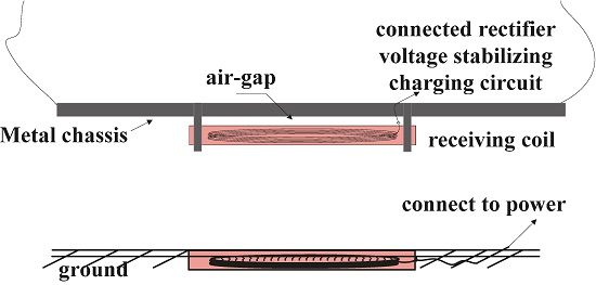
3. Modeling and Experimental Research of WPT Systems with a Single-Side Metal Plate

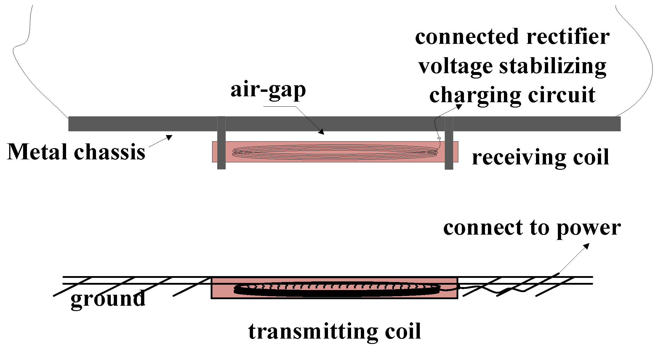
3.1. Modeling and Parameter Idetification of Systems with a Single-Side Metal Plate

A magnetic resonant WPT system includes a transmitting coil and a receiving coil, which are placed coaxially, as shown in Figure 3. The transmitting coil has N1 turns wound in a circle of radius a. The receiving coil has N2 turns wound in a circle of radius b. The metal plate is parallel to the coils and the distance from the metal plate to the transmitter and that from the plate to the receiver are c and d, respectively.
The impact of the metal plate on inductance L, mutual inductance M and resistance R can be calculated according to Equation (8). If there is no metal plate, the mutual inductance between the transmitting coil and the receiving coil can be described by:
M 0 = μ N 1 N 2 a b G ( 4 a b ( a + b ) 2 + ( c d ) 2 )
If there is a metal plate, the mutual inductance can be described as:
M = i = 1 N 1 j = 1 N 2 Δ M i j = M 0 μ a b G ( 4 a b ( a + b ) 2 + ( c d ) 2 )
In conclusion, the equivalent circuit model of systems with metal plates can be obtained, as displayed in Figure 4. Apart from the equivalent model of systems without metal plates, Figure 4 also shows the equivalent circuit model of systems using air as a medium. To simplify the analysis, the mutual inductance between the metal plate and the transmitting coil is neglected. The mutual inductance between the metal plate and the closer coil and the mutual inductance between the two coils are taken into consideration.
In Figure 4, R3 represents the loss of metal plates caused by magnetic field. L3 denotes the equivalent inductance of the metal plate. Circuit matrix equation is then expressed by:
Z I ˙ T = V ˙ T
where Z = [ R 1 + j X 1 j ω M 12 j ω M 13 j ω M 12 R 2 + R L + j X 2 j ω M 23 j ω M 13 j ω M 23 R 3 + j X 3 ] , I ˙ T = [ I ˙ 1 I ˙ 2 I ˙ 3 ] T , V ˙ T = [ V ˙ s 0 0 ] T , X1 = ωL1 − 1/(ωC1), X2 = ωL2 − 1/(ωC2), X3 = ωL3.
Since the mutual inductance between the metal plate and the transmitting coil is neglected, M13 ≈ 0. The currents in each circuit loop can be calculated by solving Equation (13) and thus, can be described by:
{ I ˙ 1 = ( Z 22 Z 33 Z 23 2 ) ξ 1 V ˙ s I ˙ 2 = Z 12 Z 33 ξ 1 V ˙ s I ˙ 3 = Z 12 Z 13 ξ 1 V ˙ s
where ξ 1 = Z 11 Z 22 Z 33 Z 11 Z 23 2 Z 12 2 Z 13 ; impedance of the transmitting coil Z 11 = R 1 + j X 1 ; impedance of the receiving coil Z 22 = R 2 + R L + j X 2 ; impedance of the metal plate Z 33 = R 3 + j X 3 ; mutual impedance between the transmitting coil and the receiving coil Z 12 = Z 21 = j ω M 12 ; mutual impedance between the transmitting coil and the metal plate Z 13 = Z 31 = j ω M 13 ; mutual impedance between the receiving coil and the metal plate Z 23 = Z 32 = j ω M 23 .
According to Equations (8) and (13), the influence of the metal plate on the receiving coil can be represented by:
{ Δ L ( ω M 23 ) 2 L 0 ( ω M 23 ) 2 + R 0 2 Δ R ( ω M 23 ) 2 R 0 ( ω M 23 ) 2 + R 0 2
Power loss caused by eddy currents is described by:
P 0 = | I ˙ 3 | 2 R 0
System transferred power and PTE can be calculated by:
{ η = | I ˙ 2 | 2 R L | I ˙ 1 | 2 R 1 + | I ˙ 2 | 2 ( R 2 + R L ) + | I ˙ 3 | 2 R 0 P = 0.5 | I ˙ 2 | 2 ( R L )

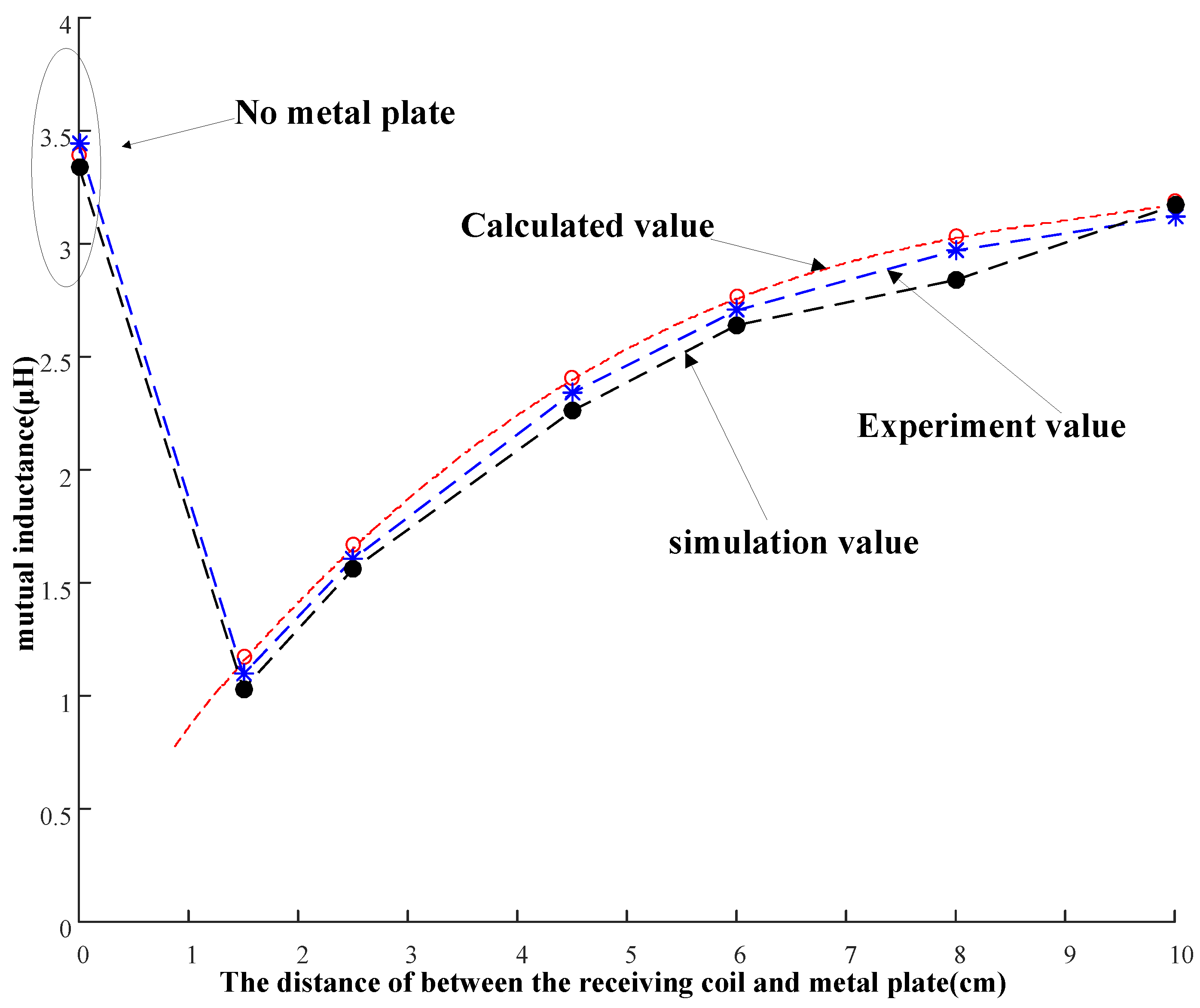
3.2. Simulation and Experimental Research of a Coil with a Single-Side Metal Plate

On the basis of theoretical analysis, simulation aided by COMSOL is carried out to analyze the parameter variations of the receiving coil working in an environment with metal plates, as shown in Figure 5a. Circular plate spiral coils are employed in this research. Coils are tightly wound so that the turn-to-turn distance is negligible. Coil parameters are specifically tabulated in Table 1.
A 3 mm thick and 30 cm long square plate made of aluminum is used in the simulation. The electric conductivity is set at 3.5 × 10⁷ S/m and the relative dielectric constant as well as the relative magnetic permeability is 1. The system is driven by a source working at 73 kHz so that a compensated capacitor of 120 nF is chosen.
To validate the theoretical and simulating results, experimental prototype using the receiving coil and the metal plate introduced above is designed and displayed in Figure 5b. The values of receiving coil inductance measured by theoretical calculations according to Equation (8), and by COMSOL, by experimental calculations are 40.67, 39.938, and 40.68 μH, respectively. The deviation between the simulation value and the theoretical value is 0.03% while the deviation between the measured value and the theoretical value is 1.8%, and both deviations demonstrate acceptable precision.
Theoretical calculation, simulation and experimental measurement are employed to quantify the influence of the metal plate on the receiving coil inductance is specifically displayed in Figure 6. The metal plate is placed at different distances from the receiving coil. Both the simulation and the experimental results validate the correctness of theoretical analysis. It also indicates that the farther the metal plate is moved away from the receiving coil, the less influence it brings about.
In this paper, the metal plate is placed near the receiving coil. Considering the distance between the metal plate and the transmitting coil is large enough (d ≥ 6 cm), the influence of the metal plate on the transmitting coil can be ignored on the basis of the above analysis. It shows that neglecting M13 is reasonable. If we replace the aluminum plate with a copper one, we can get the same results. Consequently, non-ferromagnetic materials with different electric conductivities have the same influences on coil parameters.
Based on the prototype shown in Figure 5b, the effect of frequency on the inductance of the receiving coil is analyzed and illustrated in Figure 7, which shows the changing cure of the receiving coil’s inductance vs. frequency measured by a Vector Network Analyzer (Rohde & Schwarz Technology Co, Munich, Germany). It can be seen that when the distance between the metal plate and the receiving coil is fixed, receiving coil’s inductance remains almost unchanged regardless of frequency variation. The influence is inversely proportional to the distance between the metal plate and the receiving coil, which can be clarified by the fact that a smaller d leads to a larger ΔL.

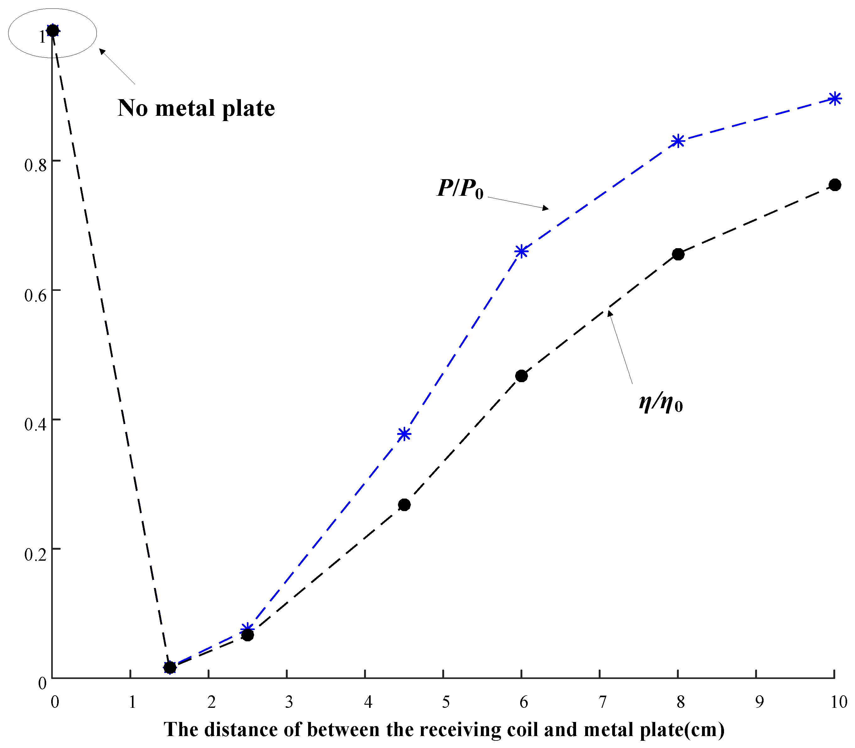
3.3. Simulation and Experimental Research of WPT System with a Single-Side Metal Plate

On the basis of the analysis above, our experimental prototype with a single-side metal plate is constructed as shown in Figure 8. In this prototype, the parameters of the transmitting coil and those of the receiving coil are as shown in Table 1. The metal plate introduced in Section 3.2 is used. According to the simulation result and the experimental measurement results shown in Figure 8 as well as Equation (12), the relationship between the mutual inductance and the metal plate distance is calculated and displayed in Figure 9.
The distance of 0 cm in Figure 9 indicates that the metal plate does not exist. The experimental measurements are also included here, presenting a consistent result. A larger distance contributes to a larger mutual inductance between the transmitting coil and the receiving coil, which indicates a smaller influence of the metal plate on the system. This is why an air gap is usually set between the receiving coil and the EVs chassis to enhance PTE for charging EVs.
The changes of transferred power and PTE in accordance to distance variations can be measured on the basis of Figure 8b. In the experiment, the distance between the transmitting coil and the receiving coil remains at 6 cm. A system with no ferrite cores or metal materials is used to power a load of 2 Ω, and the transferred power and the PTE are 10 W and 80% respectively, which are taken as the reference values to normalize the performance of a system with a metal plate, as displayed in Figure 10. Similar to Figure 9, the metal plate is not used when the distance is 0 cm. It can be concluded that there is a continuous increase in both transferred power and PTE when the distance increases. In other words, the effect of the metal plate is declining. When the metal plate is placed at a distance of 1.5 cm away from the receiving coil (quite close to the receiving coil), transferred power is extremely low due to the influences of the metal plate, while, the PTE is approximately 3.2%, which can be mainly caused by the fact that the existence of the metal plate leads to the detuning of the receiving coil. This would definitely have an adverse influence on system operations and exacerbate system performance. Therefore, in order to address this problem, WPT systems with a single-side metal plate should be improved and optimized.

4. Performance Improvement of WPT System with a Single-Side Metal Plate

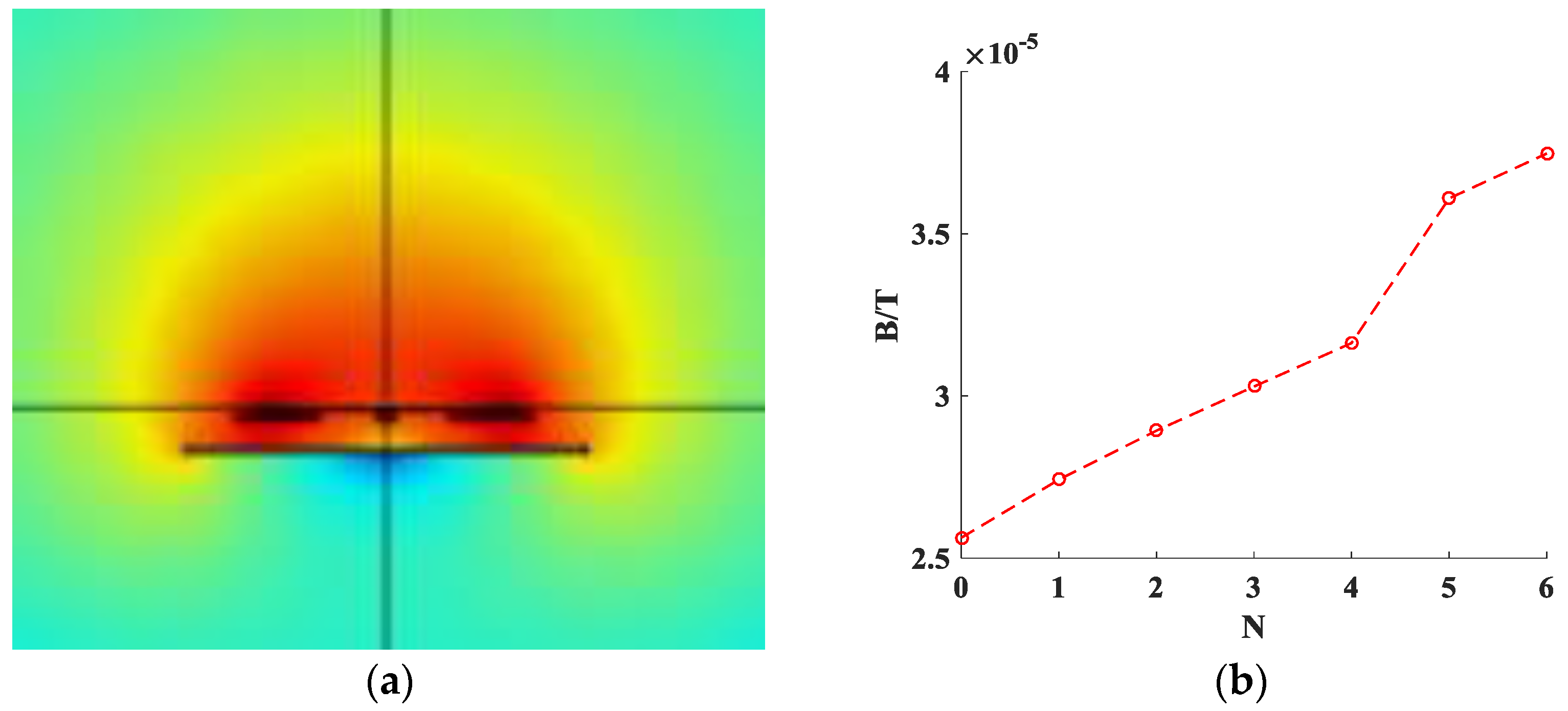
4.1. Application of Ferrite Cores and Its Effect on the Receiving Coil

The metal plate is supposed to absorb the magnetic field so the coil inductance decreases accordingly. As a result, it is necessary to reduce the effect of the metal plate on coils by limiting the electromagnetic field intensity. Several ferrite cores are placed between the receiving coil and the metal plate, through which the electromagnetic field in a close region can be enhanced. As a result, the leakage field is reduced and both self-inductance and mutual inductance are increased. Nevertheless, the use of ferrite cores produces power loss due to eddy current. The power loss is proportional to electric conductivity σ and frequency f2. Consequently, materials with small conductivity are preferred to improve PTE. The ferrite cores used in the paper are a DMR95 Mn-Zn with specific dimensions of 7 cm × 2 cm × 0.5 cm. The standard power loss is 300 mW/cm3@100 kHz, 200 mT, much smaller than that of metal materials whose conductivity is 3500–4500@(80–120 kHz). As a result, power loss caused by the eddy current is extremely low.
According to Figure 5a, the COMSOL simulation model of a system consisting of a receiving coil, a metal plate and ferrite cores placed between them is shown in Figure 11. The magnetic field intensity at the center of the coil is displayed. The distance between the metal plate and the receiving coil is 1.5 cm and the excitation current is 1 A.
When ferrite cores are not used, the magnetic field intensity is around 25 μT as shown in Figure 12. With the increase in the number of ferrite cores, the magnetic field intensity increases obviously, to about 39 μT by 56% when six ferrite cores are used. Since self-inductance of the coil is proportional to the magnetic field intensity, so the application of the ferrite cores is a feasible way to enhance the self-inductance.
According to the analytical results above, the simulation and experimental results of the relationship between the coil’s self-inductance and the number of ferrite cores when the metal plate is not used are illustrated in Figure 13, which shows that more ferrite cores contribute to a larger coil inductance. Six ferrite cores, whose sequence numbers represent different locations, are used as shown in Figure 11a, and the inductance is increased to 46 μH by 15%. It should be noted that there is only one ferrite core in each location, for example, sequence ⑤ represents that a ferrite core is placed at the position ⑤.
If the power loss is ignored, the results in Figure 6 and Figure 13 demonstrate that proper distribution of ferrite cores can increase the inductance while the metal plate has an adverse impact on it. According to the resonant frequency determined by f = 1/2π(LC)0.5, the use of ferrite cores which leads to the increase in inductance also results in a decrease of the resonant frequency. On the contrary, the metal plate which results in the decrease in inductance increases the resonant frequency. As a consequence, the proper distribution of a number of ferrite cores is able to eliminate the influence brought by the metal plate completely, which is vital to system stability. The metal plate is placed at a distance of 1.5 cm apart from the receiving coil, and the ferrite cores are added one by one in the sequence as illustrated by Figure 11, the simulation results and the measured results are tabulated in Table 2.
The results in Table 2 further validate the feasibility of offsetting the influence of a metal plate by using ferrite cores. It should be noted that the needed number of ferrite cores changes in accordance with the distance variations between the metal plate and the receiving coil.

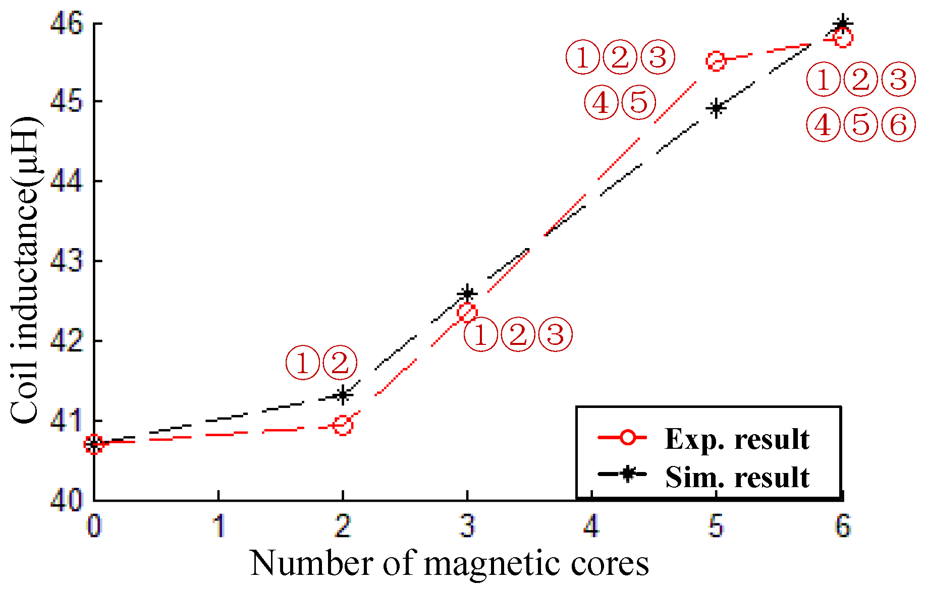
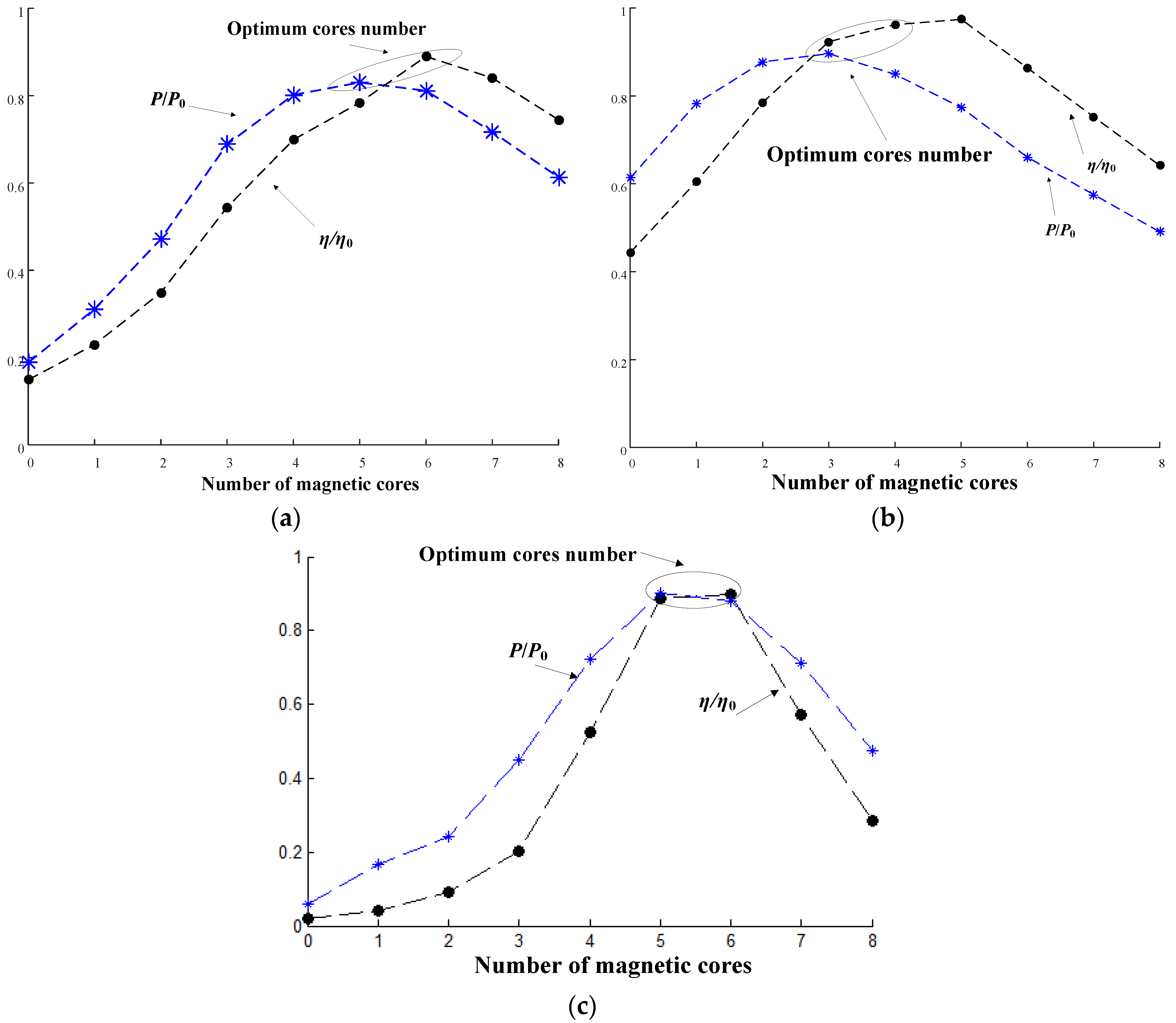
4.2. Comparative Experiments on Performance of Systems with and without Ferrite Cores

System performance enhancement by using magnetic materials (ferrites) is further investigated. If the transferred power and the PTE are set as benchmarks when the system has no metal or ferrite material between two coils and in surrounding areas, by normalizing measured results for a second time, we can get the variation curve of PTE and that of transferred power in accordance to the distance between the metal plate and the receiving coil as shown in Figure 14.
According to Figure 14, with the increase of ferrite cores, the influence of metal plate on receiving coils is weakened, and the optimum is achieved in a certain condition. When the optimal state is reached, the enhancement effect of ferrite cores on the inductance of receiving coil and the weakening effect of metal plate on receiving coils offset each other, and the system is in a resonance state again. Such as Figure 14, when the distance is 1.5 cm, the number of cores is about 5–6; for a distance of 3.5 cm, the number is about 4–5; for a distance of 6cm, the number is about 3–4. When the number of cores is optimal, the influence of metal plate on receiving coils can be basically offset. At this time, transferred power and PTE had returned to 90% in the presence of metal plate. Of course, it is difficult to recover completely, because there are losses in both the metal plate and the ferrite cores, such as eddy current loss or hysteresis loss, etc. With the increase in the number of ferrite cores, the effect of ferrite cores on a receiving coil plays a major role, which sets WPT systems in a state of disharmony, so the transferred power and PTE of WPT systems are decreased again. When the transmission distance is 6cm, the system input voltage, output voltage and current waveforms are shown in Figure 15.
In summary, the aforementioned results demonstrate that by using a strong magnetic conductive material placed between metal objects and receiving coil reasonably, we can reduce the effect of metal objects on WPT systems effectively and maximize PTE.

5. Discussion

Problems caused by metal materials have to be tackled to guarantee applications of WPT technology in many fields, such as charging for EVs, smart-phones, intelligent household appliances, other relevant industries and so on. The magnetic field caused by metals results in a decrease of system performance. In addition, the modeling and analysis in such a complicated environment are hard to implement since it includes coupling of magnetic field, electric field and heat field. Researches addressing these issues are still at the beginning. The paper intends to improve PTE of WPT systems working in the environment with metal materials and reduce the influence of these metal materials on system performance.
To be more specific, a non-ferromagnetic metal plate is used in this paper to simulate the working environment with metal materials. A basic analysis is completed and corresponding solutions to improve PTE are proposed. High-frequency magnetic conductive materials are employed and the system performance is obviously enhanced by their proper distribution, which provides a feasible way to tackle problems in a WPT system with a single side metal plate. Meanwhile, quantitative analysis is not carried out due to the complexity of the system working in the environment with metal materials, so simulation combined with experimental verification is widely used in the paper, causing difficulties in system design. Moreover, the use of magnetic materials increases the overall costs. The compromise between reducing expenses and developing technology to improve system performance is what we need to consider in future research. Anyway, the performance improvement of WPT systems working in the environment with metal materials is of great significance to promote the wide applications of WPT technology.

6. Conclusions

This paper studies the effect of non-ferromagnetic metal plates on resonant WPT systems, and establishes an impedance model containing metal plates. Through comparing the model calculation results, the simulation results and the experimental results, which are in accord with each other, we verify the correctness of the model. When a non-ferromagnetic metal material exists around coils, the intrinsic resonant frequency is lowered, and the effect caused by the metal material around the coil produces eddy current loss, which is not conducive to the effective transmission of the energy system. Therefore this paper uses the magnetic characteristics of the magnetic material, and rebuilds the circulation channel for magnetic field between the metal plate and coils, thus weakening its effect on the coils. By means of theoretical analysis and experiment, this paper proves the correctness of this approach.
The performance improvement of WPT systems with metal is not only a complicated math problem, but also a key problem which needs to be solved urgently practical application. This paper only investigates systems with non-ferromagnetic metal plates, but our research results provide certain reference values in irregular metal system modeling, and a feasible solution to improve system performance in the metal environment.

Acknowledgments

This work was supported in part by National Nature Science Youth Foundation of China (No. 51507032), Nature Science Youth Foundation of Jiangsu Province (No. BK20150617), the Fundamental Research Funds for the Central Universities, and Science and Technique Project Funds of State Grid Jiangsu Electric Power Company (No. J2016021).

Author Contributions

Linlin Tan designed the model and performed the calculations and experiments. Linlin Tan, Xueliang Huang and Jiacheng Li proposed the research topic and analyzed the data. Chen Chen, Jinpeng Guo, and Changxin Yan helped write part of the simulation programs. All authors contributed to the writing of the manuscript, and have read and approved the final manuscript.

Conflicts of Interest

The authors declare no conflict of interest.

References

  1. Shinohara, N. Power without wires. IEEE Microw. Mag. 2011, 12, S64–S73. [Google Scholar] [CrossRef]
  2. Kim, J.; Sun, C.; Suh, I. A proposal on wireless power transfer for medical implantable applications based on reviews. In Proceedings of the 2014 IEEE on Wireless Power Transfer Conference (WPTC), Jeju, Korea, 8–9 May 2014; pp. 166–169.
  3. Shin, J.; Shin, S.; Kim, Y.; Ahn, S.; Lee, S.; Jung, G.; Jeon, S.; Cho, D. Design and Implementation of Shaped Magnetic-Resonance-Based Wireless Power Transfer System for Roadway-Powered Moving Electric Vehicles. IEEE Trans. Ind. Electron. 2013, 61, 1179–1192. [Google Scholar] [CrossRef]
  4. Taylor, J.A.; Low, X.N.; Casanova, J.; Lin, J. A wireless power station for laptop computers. In Proceedings of the 2010 IEEE on Radio and Wireless Symposium (RWS), New Orleans, LA, USA, 10–14 January 2010; pp. 625–628.
  5. Kim, J.; Bien, F. Electric field coupling technique of wireless power transfer for electric vehicles. In Proceedings of the 2013 IEEE on TENCON Spring Conference, Sydney, Australia, 17–19 April 2013; pp. 267–271.
  6. Cho, I.; Kim, S.; Moon, J.; Yoon, J.; Jeon, S.; Choi, J. Wireless power transfer system for docent robot by using magnetic resonant coils. In Proceedings of the 2013 IEEE 5th International Symposium on Microwave, Antenna, Propagation and EMC Technologies for Wireless Communications (MAPE), Chengdu, China, 29–31 October 2013; pp. 251–254.
  7. Wang, Z.; Wei, X.; Dai, H. Design and Control of a 3 kW Wireless Power Transfer System for Electric Vehicles. Energies 2015, 9, 10. [Google Scholar] [CrossRef]
  8. Basar, M.R.; Ahmad, M.Y.; Cho, J.; Ibrahim, F. Application of wireless power transmission systems in wireless capsule endoscopy: An overview. Sensors 2014, 14, 10929–10951. [Google Scholar] [CrossRef] [PubMed]
  9. Kang, J.; Park, H.; Jang, J.; Lee, K. A design of wide input range, high efficiency rectifier for mobile wireless charging receiver. In Proceedings of the 2014 IEEE on Wireless Power Transfer Conference (WPTC), Jeju, Korea, 8–9 May 2014; pp. 154–157.
  10. Son, H.; Kim, J.; Park, Y.; Kim, K. Efficiency analysis and optimal design of a circular loop resonant coil for wireless power transfer. In Proceedings of the 2010 Asia-Pacific Microwave Conference, Yokohama, Japan, 7–10 December 2010; pp. 849–852.
  11. Chen, W.; Chinga, R.A.; Yoshida, S.; Lin, J.; Chen, C.; Lo, W. A 25.6 W 13.56 MHz wireless power transfer system with a 94% efficiency GaN Class-E power amplifier. In Proceedings of the 2012 IEEE MTT-S International Microwave Symposium Digest (MTT), Montreal, QC, Canada, 17–22 June 2012; pp. 1–3.
  12. Campi, T.; Cruciani, S.; Feliziani, M. Magnetic shielding of wireless power transfer systems. In Proceedings of the 2014 International Symposium on Electromagnetic Compatibility (EMC’14/Tokyo), Tokyo, Japan, 12–16 May 2014; pp. 422–425.
  13. Kim, J.; Kim, J.; Kong, S.; Kim, H.; Suh, I.; Suh, N.P.; Cho, D.; Kim, J.; Ahn, S.; Ahn, S. Coil Design and Shielding Methods for a Magnetic Resonant Wireless Power Transfer System. Proc. IEEE 2013, 101, 1332–1342. [Google Scholar] [CrossRef]
  14. Kudo, H.; Ogawa, K.; Oodachi, N.; Deguchi, N.; Shoki, H. Detection of a metal obstacle in wireless power transfer via magnetic resonance. In Proceedings of the 2011 IEEE 33rd International Telecommunications Energy Conference (INTELEC), Amsterdam, The Netherland, 9–13 October 2011; pp. 1–6.
  15. Ogawa, K.; Oodachi, N.; Obayashi, S.; Shoki, H. A study of efficiency improvement of wireless power transfer by impedance matching. In Proceedings of the 2012 IEEE MTT-S International Microwave Workshop Series on Innovative Wireless Power Transmission: Technologies, Systems, and Applications (IMWS), Kyoto, Japan, 10–11 May 2012; pp. 155–157.
  16. Kim, S.; Park, H.; Kim, J.; Kim, J.; Ahn, S. Design and Analysis of a Resonant Reactive Shield for a Wireless Power Electric Vehicle. IEEE Trans. Microw. Theory Tech. 2014, 62, 1057–1066. [Google Scholar] [CrossRef]
  17. Moon, H.; Kim, S.; Park, H.H.; Ahn, S. Design of a Resonant Reactive Shield with Double Coils and a Phase Shifter for Wireless Charging of Electric Vehicles. IEEE Trans. Magn. 2015, 51, 1–4. [Google Scholar] [CrossRef]
  18. Kaneda, J.; Miwa, K.; Kikuma, N.; Hirayama, H.; Sakakibara, K. Relation analysis between feeding structures and effect of shield for coils in wireless power transfer with magnetically coupled resonance. In Proceedings of the 2012 International Symposium on Antennas and Propagation (ISAP), Nagoys, Japan, 29 October–2 November 2012; pp. 1208–1211.
  19. Kitano, Y.; Omori, H.; Morizane, T.; Kimura, N.; Nakaoka, M. A new shielding method for magnetic fields of a wireless EV charger with regard to human exposure by eddy current and magnetic path. In Proceedings of the 2014 International Power Electronics and Application Conference and Exposition, Shanghai, China, 5–8 November 2014; pp. 778–781.
  20. Feliziani, M.; Cruciani, S. Mitigation of the magnetic field generated by a wireless power transfer (WPT) system without reducing the WPT efficiency. In Proceedings of the 2013 International Symposium on Electromagnetic Compatibility (EMC EUROPE), Brugge, Belgium, 2–6 September 2013; pp. 610–615.
  21. Lawson, J.; Yates, D.C.; Mitcheson, P.D. Efficient artificial magnetic conductor shield for wireless power. In Proceedings of the 2015 IEEE on Wireless Power Transfer Conference (WPTC), Boulder, CO, USA, 13–15 May 2015; pp. 1–4.
  22. Selection of Single-Wire Nominal Diameter. Available online: http://www.elektrisola.com/en/hf-litz-wire/terminology-basics/selection-of-litz-wire-parameters.html (accessed on 3 May 2016).
  23. Tan, L.L.; Huang, X.L.; Huang, H.; Zou, Y.W.; Li, H. Transfer efficiency optimal control of magnetic resonance coupled system of wireless power transfer based on frequency control. Sci. China Technol. Sci. 2011, 54, 1428–1434. [Google Scholar] [CrossRef]
  24. Pantic, Z.; Lukic, S. Computationally-Efficient, Generalized Expressions for the Proximity-Effect in Multi-Layer, Multi-Turn Tubular Coils for Wireless Power Transfer Systems. IEEE Trans. Magn. 2013, 49, 5404–5416. [Google Scholar] [CrossRef]
Figure 1. The interaction between EVs wireless charging system and metal plate.
Energies 09 00576 g001
Figure 2. Position distributions of single turn coil and metal plate.
Energies 09 00576 g002
Figure 3. Position relation between two coils and the metal plate.
Energies 09 00576 g003
Figure 4. System equivalent circuit with metal plate.
Energies 09 00576 g004
Figure 5. (a) Simulation model; (b) Experiment model.
Energies 09 00576 g005
Figure 6. Effect of different distances between the receiving coil and the metal plate on the coil inductance.
Energies 09 00576 g006
Figure 7. Effect of frequency on inductance parameters of the receiving coil.
Energies 09 00576 g007
Figure 8. (a) Simulation model; (b) Experiment model.
Energies 09 00576 g008
Figure 9. Effect of metal plate’s distance on the mutual inductance between coils.
Energies 09 00576 g009
Figure 10. Effect of metal plate‘s distance on transferred power and PTE of systems.
Energies 09 00576 g010
Figure 11. System model with ferrite cores: (a) 2D model; (b) 3D simulation model.
Energies 09 00576 g011
Figure 12. (a) Magnetic field distribution; (b) Magnetic changing curve vs. numbers of ferrite cores.
Energies 09 00576 g012
Figure 13. Effect of ferrite cores on inductance parameters of the receiving coil.
Energies 09 00576 g013
Figure 14. Experimental results: (a) The distance between metal plate and receiving coil is 3.5 cm; (b) The distance between metal plate and receiving coil is 6 cm; (c) The distance between metal plate and receiving coil is 1.5 cm.
Energies 09 00576 g014
Figure 15. When the metal plate is 6cm away from the receiving coil, input current-voltage and output current-voltage waveforms vary with different numbers of cores: (a) without cores; (b) with 8 cores; (c) with 6 cores; (d) with 3 cores.
Energies 09 00576 g015aEnergies 09 00576 g015b
Table 1. Coil parameters.
ParameterValue
External radius20 cm
Inner radius16 cm
Coil turns N10
Wire diameter2 mm
Frequency f73 kHz
Inner resistance R0.05 Ω
Table 2. Receiving coil’s parameter variation.
Ferrite CoresCoil Inductance (μH)Resonant Frequency (kHz)
Simulation ValuesMeasured ValuesSimulation ValuesMeasured Values
None23.40123.4294.9894.75
28.4828.5686.0985.97
①②30.5730.5983.0883.01
①②③④34.2534.1778.5178.39
①②③④⑤35.7635.2076.8376.82
①②③④⑤⑥39.6540.0472.9672.95

