Article

A Coordinated Control for Photovoltaic Generators and Energy Storages in Low-Voltage AC/DC Hybrid Microgrids under Islanded Mode

1
Zhuhai Power Supply Bureau of Guangdong Power Grid Corporation, Zhuhai 519000, China
2
School of Information Science and Engineering, Central South University, Changsha 410083, China
3
Department of Energy Technology, Aalborg University, Aalborg East DK-9220, Denmark
*
Author to whom correspondence should be addressed.
Energies 2016, 9(8), 651; https://doi.org/10.3390/en9080651
Submission received: 30 May 2016 / Revised: 9 August 2016 / Accepted: 10 August 2016 / Published: 17 August 2016
(This article belongs to the Special Issue Decentralized Management of Energy Streams in Smart Grids)

Abstract

:
The increasing penetration of renewable generators can be a significant challenge due to the fluctuation of their power generation. Energy storage (ES) units are one solution to improve power supply quality and guarantee system stability. In this paper, a hybrid microgrid is built based on photovoltaic (PV) generator and ES; and coordinated control is proposed and developed to achieve power management in a decentralized manner. This control scheme contains three different droop strategies according to characteristics of PV and ES. First, the modified droop control is proposed for PV, which can take full utilization of renewable energy and avoid regulating output active power frequently. Second, to maintain the direct current (DC) bus voltage stability, a novel droop control incorporating a constant power band is presented for DC-side ES. Third, a cascade droop control is designed for alternating current (AC)-side ES. Thus, the ES lifetime is prolonged. Moreover, interlinking converters (ICs) provide a bridge between AC/DC buses in a hybrid microgrid. The power control of IC is enabled when the AC- or DC-side suffer from active power demand shortage. In particular, if the AC microgrid does not satisfy the reactive power demand, IC then acts as a static synchronous compensator (STATCOM). The effectiveness of the proposed strategies is verified by simulations.

Graphical Abstract

1. Introduction

Recently, distributed generation (DG) has attracted more attention due to the perceived advantages of easy integration of resources, high energy utilization efficiency, flexible installation location, and low power transmission losses [1,2]. Therefore, DG penetration in the main grid has gradually increased, and may potentially be a future trend in electric power system development [3].
As an effective carrier of distributed energy, a microgrid consists of various DG units, energy storage (ES) devices, energy conversion devices, protections, and load monitoring devices. These DG units always possess a higher degree of controllability and operability compared to conventional generators [4,5,6]. Resulting from these features, a microgrid could play a critical role in maintaining the stability of the electrical networks [7,8,9]. Among various DGs, photovoltaic (PV) generator has emerged as major DG source in power grids [10].
The power supply quality of an alternating current (AC) microgrid is significantly influenced by intermittence and fluctuation of the distributed power. Moreover, a number of AC-distributed resources are connected to the microgrid through a multi-stage conversion controller, which lowers the system efficiency to some extent [11,12,13,14,15]. As an alternative to an AC microgrid, a direct current (DC) distribution microgrid has several attractive features and is developed in [16,17]. First, the DC microgrid allows easier integration of DGs, requiring lower conversion stages. Second, the power quality is enhanced as the harmonic distortion and synchronization issues are inherently eliminated. Especially, the complexity of its control system is greatly reduced when compared with the AC system. The DC microgrid has a low installation and operation cost. However, DC microgrid has a potential disadvantage in that it is not suitable for the rural low voltage networks due to their large line resistance.
For a DC microgrid powered by PV generator and battery, the AC adaptors of common portable electronic devices could work properly through reasonable selection of control parameters. However, for a single AC or DC microgrid, a multistage conversion is needed due to the different AC/DC types of DGs and loads. The complexity is increased and the efficiency is reduced. To facilitate the integration of AC- and DC-type loads, hybrid AC/DC microgrid architecture has been extensively investigated [18,19,20,21,22,23]. On one hand, the DC and AC type loads are directly fed by the DC- and AC-side microgrid, respectively. On the other hand, the interlinking converter (IC) provides bidirectional energy transfer between the DC and AC subgrids, depending on their individual supply demand conditions. Meanwhile, the plug-and-play function is realized by controlling the power electronic converters.
This paper focuses on power control strategies of a hybrid microgrid in islanded mode. In a previous study, the master-slave control method is adopted in [24], which requires the communication between the master and slave controller. The master node is still a single point-of-failure. There have been some other power flow management methods based on communication [25,26]. In [25], a centralized controller is proposed to generate a compensation signal of primary layer. Thus, an accurate and optimized power exchange between two subgrids is provided. In [26], a three-level hierarchical control for parallel ICs between AC bus and DC bus in a hybrid microgrid is presented. The bus voltage deviation caused by the droop control in the primary control level is restored, and proportional current sharing is accomplished. However, the external communication would increase the investment cost and reduce reliability and expandability of the system.
To overcome this drawback, decentralized control strategies without communication are preferable. Autonomous operation of a hybrid microgrid is investigated in [15] and extended in [20,27]. Firstly, reference [15] proposes a droop control strategy for controlling the ICs by a normalized bidirectional droop scheme. Proportional active power sharing can be enforced based on ratings. However, the principle proposed in [15] causes the continuous action of IC during any slip DG or load power variations, leading to more power loss. In [27], an ES system is linked to the DC terminal of the IC, and proper charging and discharging of ES is demonstrated. In [20], an efficient power flow control scheme is presented for hybrid microgrid with progressive energy flow tuning. It allows energy flow across the IC only when one subgrid is over-loaded and the other subgrid is light-loaded. Moreover, reference [28] proposes a fully decentralized control to achieve local power sharing (LPS) in an individual AC or DC network, global power sharing (GPS) throughout AC/DC networks and storage power sharing (SPS). The intended outcome is to activate as few power converters as possible, in order to avoid their operating losses. Although the various conditions are well designed, the associated mode switching among LPS, GPS, and SPS is slightly complex and easy to lose stability. Moreover, it should not be ignored that both the AC- and DC-distributed generators are treated as ideal power source, which does not consider the characteristics of DGs in [15,20,27,28].
There are also some models and control methods that involve integrating the actual distributed resources. Typically, a model of a hybrid microgrid is studied in [29] based on the Wind-PV-ES units. The equivalent circuit of the whole system is developed in both isolated and grid tied modes. However, the operating principle of an IC is not practical to coordinate both of the subgrids. References [30,31,32] propose a control strategy of Vg/VDC droop and P/VDC anti-droop control strategy for PV panels. It avoids frequent energy fluctuation and improves the quality of output voltage, but does not take into account the coordination control of multiple DG units. For the optimal operation of hybrid microgrid [33,34], a simple algorithm is developed to determine the required sizing of generating units and the associated storage capacity in [33]. However, it requires the state of charge information of the battery in real-time.
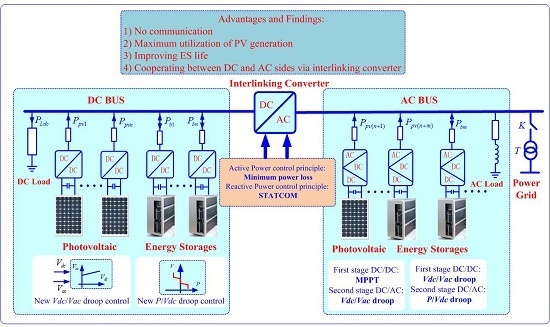
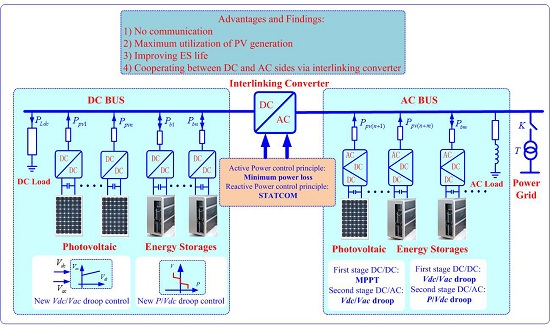
In this paper, a coordinated power control paradigm is proposed in a hybrid microgrid by considering the characteristics of DG units and designing the effective principle of an IC. The potential advantages are summarized below:
(1)
Power flow control is realized in a fully decentralized manner.
(2)
To harness the maximum power of PV units, a modified droop control is proposed.
(3)
To prolong the lifetime of ES, a novel droop control incorporating a constant power band is presented.
(4)
To improve the system efficiency, an effective principle of an IC is developed to coordinate both AC and DC subgrid microgrids.
This paper is organized as follows: in Section 2, this work starts with a hybrid microgrid architecture based on PV and ES. In Section 3, the VDC/VAC droop control strategy and its combination with P/VDC droop control are presented, as well as their characteristics. Then, the strategy of the IC is introduced in Section 4. Simulation results with these control principles are shown and discussed in Section 5. Finally, Section 6 presents the conclusions.

2. System Structure

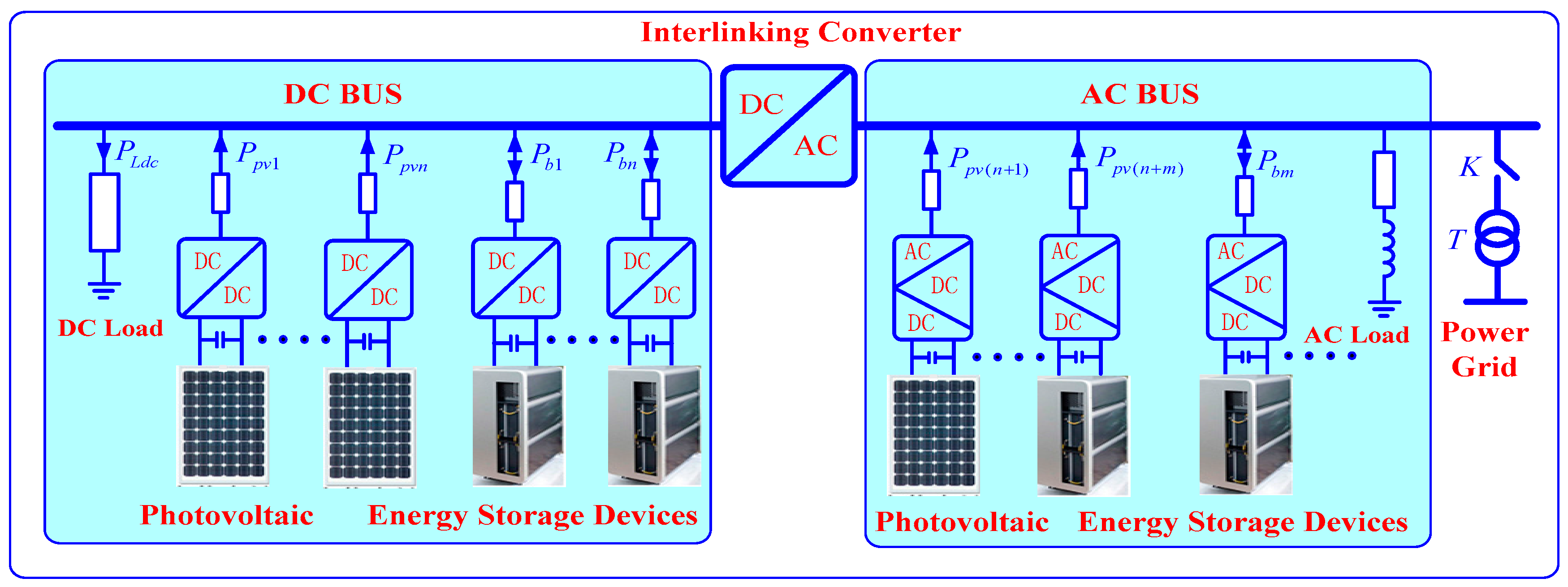
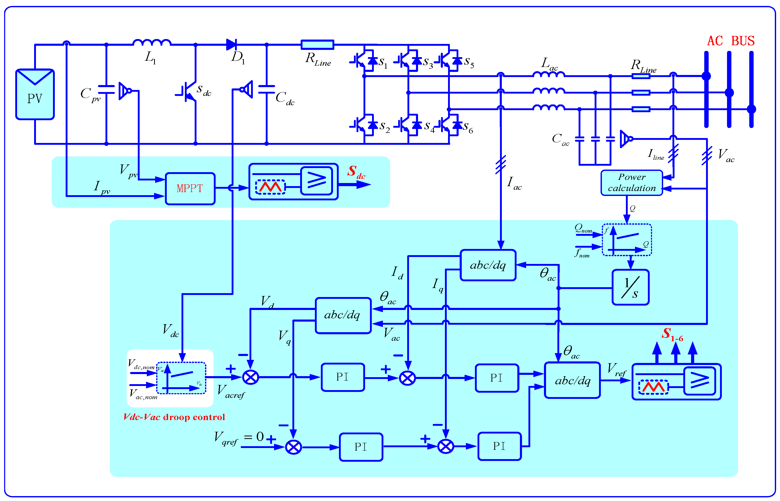
Figure 1 shows a hybrid microgrid formed by an AC microgrid and a DC microgrid. Each microgrid has its own PV sources, storages, and the same of type loads grouped together in order to minimize the amount of power conversion. PV sources of DC system are connected to a DC bus through a DC/DC boost converter, while the storage device is linked by a DC/DC buck-boost converter [11]. On the other hand, the PV and storage generation of AC system are connected to AC bus through a cascaded DC/DC/AC converter [34,35,36].
Regardless of the number of ICs, their role is to provide bidirectional energy transfer between two sides, depending on their prevailing internal supply-demand conditions [15]. Furthermore, a hybrid microgrid can be tied to the AC main grid through an intelligent transfer switch. This switch would stay on under a normal grid-connected mode. If the main grid is strong with sizable capacity, the supply-demand power balance of hybrid microgrid can be guaranteed by the main grid. When a fault is sensed in the main grid, the transfer switch would turn off, forming an autonomous hybrid microgrid [27].
For the islanded mode of hybrid AC/DC microgrid, control strategies and power management schemes are the critically important tasks. The power management strategies determine the output active and reactive powers of DG and ES units, and control the voltage and frequency at the same time. Details of the strategies for the different types of DGs and ES units are explained in next section.

3. Proposed Power Control Strategy of Hybrid AC/DC Microgrid

In this Section, a control strategy based on the VDC/VAC droop and its combination with P/VDC droop control method is proposed for power management. Then, the control structures of PVs and ES units are discussed in details.

3.1. VDC/VAC Droop Control (Droop-1)

The VDC/VAC droop control principle is based on the specific characteristic of islanded microgrids, which differs significantly from the conventional power system. In a microgrid, the DG unit is generally linked to the AC bus through the power electronic converter with a DC-side capacitor, as shown in Figure 2.
If the generated power and absorbed power becomes unbalanced, the DC-side capacitor voltage VDC of the power sources would change. According to Figure 2, the VDC can be mathematically derived as follows:
C d V DC d t = i prim i DC
where iprim and iDC present the current of prime sources and input terminal in inverter, respectively. From Equation (1), VDC is used as the trigger for power changes.
Furthermore, the line parameter of the low voltage microgrid is mainly resistive. Assuming that the line inductance is neglected, the active and reactive powers from one unit can be expressed as follows [37]:
P = V AC V R cos ϕ V 2 R
Q = V AC V R sin ϕ
where VAC is the amplitude of the inverter output voltage, V is the common bus voltage, φ is the power angle, and R is the line resistance. P and Q are the output active and reactive powers of a DG, respectively.
According to Equation (2), the active power P depends on the voltage amplitude VAC, unlike in transmission grids where the reactive power is linked with the voltage amplitude [37].
Therefore, the relationship between VDC and VAC can be constructed to change the active power, which forms the basis of the new VDC/VAC droop control:
V AC = V AC,nom + m ( V DC V DC,nom )
where VAC,nom and VDC,nom are the nominal voltages of the AC- and DC-sides of the power converter, respectively. Note that a slight change of VAC results in a change of the transmitted energy from DG to the common bus. m is the slope of the VDC/VAC droop. VAC and VDC are the AC- and DC-side voltages of the power converter, respectively.
The plot illustrating the new VDC/VAC droop control is depicted in Figure 3. With this controller, the microgrid voltage is changed by detecting changes of VDC, and the supply-demand balance is achieved without changing output active power P. Generally, frequent power changes are avoided, and no communication for the primary control is required. The tolerated voltage deviation from its nominal value is effectively used. Moreover, both controllers take the specific characteristics of an islanded AC microgrid into account, such as the lack of inertia, resistive lines, and high share of distributed generators.
In this AC voltage range (±5%), the DG units are actively dispatched as they operate at maximum power point tracking (MPPT). This is particularly advantageous for DGs since their energy can be used more efficiently. According to this rule, a PV generation of the DC-side in a hybrid microgrid, which consists of the PV array, DC/DC converter, and local control, should operate in the MPPT mode based on the perturb and observe (P & O) method [38,39]. On the other hand, the PV generation system of AC-side consists of the PV array, cascaded DC/DC/AC converter, output filters, and local control system. The front-stage converter adopts the MPPT method, while the second-stage utilizes the newly proposed VDC/VAC droop control. The overall control scheme of PV generation of the AC-side is shown in Figure 4.
For reactive power control of PVs in the AC-side, the Q-f boost method is adopted by considering Equation (3) in a low-voltage hybrid microgrid [37]:
f = f * + m ( Q Q * )
where f* represents the frequency reference value at a normal load, m is droop gain, and Q and Q* are the output reactive power and its normal reference of a DG unit, respectively.

3.2. P/VDC Droop Control (Droop-2)

When the VDC/VAC droop control is adopted, the AC microgrid voltage is allowed to change within a certain range. If the load changes dramatically, the DC capacitor voltage will exceed the specified range, thus deteriorating the public bus voltage of AC microgrid. Hence, a new P/VDC droop control with a constant power band should be proposed. The active power P (or DC current IDC) is changed according to a droop with the microgrid DC voltage VDC:
V DC = V DC,nom k p ( P P nom )
where kp is the positive droop coefficient and Pnom is the nominal value of the active power P.
The schematic diagram of the P/VDC droop control strategy with constant power band is depicted in Figure 5. In this figure, the constant power band is adopted within the allowable voltage deviation (±5%). If the loads severely change, exceeding the acceptable voltage range, the P/VDC droop control strategy is enabled to share the load and maintain the microgrid voltage. When the output power of the ES unit reaches its capacity limit, the maximum value of the power is controlled to ensure the stability and security.
The proposed P/VDC droop control strategy with a constant power band (Droop-2) is suitable for a DC-side ES unit as shown in Figure 6. When the load change is small, the battery is controlled in the constant power mode. It can avoid a battery charge and discharge frequently, so as to improve the battery life. If the DC voltage exceeds the specified interval, the P/VDC droop control is switched. Then the active power sharing performance is obtained.

3.3. Combination of VDC/VAC and P/VDC Droop Control (Droop-3)

The combination of two control principles VDC/VAC droop control and P/VDC droop control is introduced in order to utilize the advantages of both. With the VDC/VAC droop control, the microgrid voltage can be changed by detecting changes of VDC, and supply-demand balance is achieved without changing the active power P. It is possible because a relatively big difference between the obtained and nominal microgrid voltages is allowed. By using the P/VDC droop control, the active power P can be changed when the constant power band is surpassed, increasing the power flexibility of the microgrid and avoiding a voltage-limit violation. The obvious advantage is that by using these two droop controllers, the output active power of PV or storage elements changes less frequently than that in the case with only the P/VDC droop control.
The width of the constant power band could be set according to the specific characteristics of the power sources. For example, the width can be narrow for a battery, which can change its intake fuel rapidly. In this way, the control capability of these sources are fully exploited. For less controllable sources, such as PV array power generators, the width should be larger. In this paper, the PV generation is always operating in the MPPT mode. In other words, the width is infinite in order to make full utilization of the output power. This combined droop control is suitable for battery control on the AC-side. The overall control scheme of the ES unit on the AC-side is depicted in Figure 7.

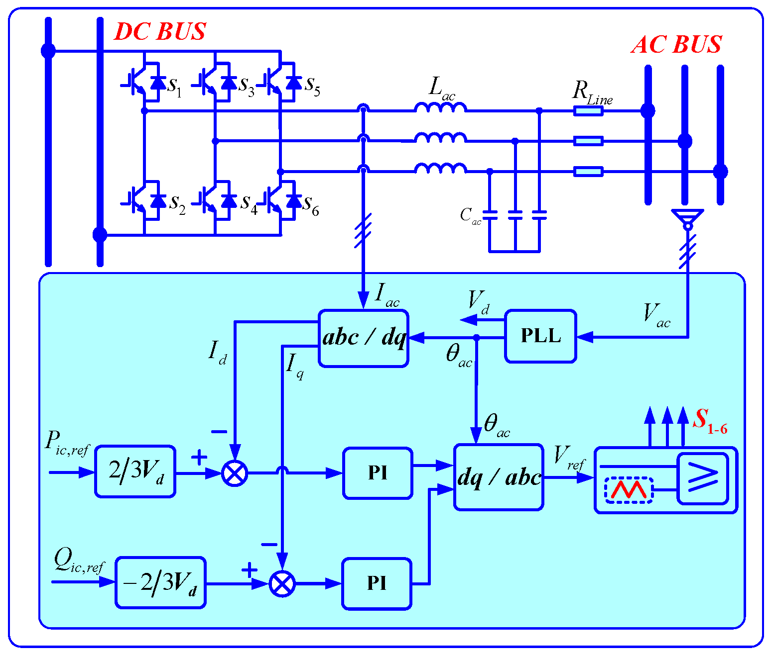
4. Proposed Power Control Strategy for the Interlinking Converter

As a common bridge of connecting AC/DC buses in a hybrid microgrid, ICs play an important role when the hybrid microgrid operates under varying generation and load conditions. Therefore, designing the control mechanism and timing of energy transmission is the key to controlling the IC. In this paper, the principle of minimizing power transfer between the sub-grids is designed to guarantee the overall system efficiency.
If one of the AC/DC sub-grids is capable of providing the load by itself while the other cannot provide the demanded load fully, the active power control of the IC is activated. On the other hand, another scenario is permissible whereby both sides are capable of individually charging the storages without a triggering energy transfer. Therefore, operating losses of the IC are avoided, resulting in a higher overall system efficiency. Regarding the reactive power, if the AC microgrid does not satisfy the reactive power demand, the reactive power control for IC can operate as a static synchronous compensator (STATCOM) to satisfy the demand. Thus, the Q-f droop control strategy can be applied in reactive power sharing [37].
To realize the above scenarios physically in mathematical formulations, the appropriate amount of charging power is first determined. When the active power flow of the AC/DC bus exceeds 80% of the overall power capacity, the energy transmission indicator G(AC) or G(DC) is set as follows:
G ( AC ) = { 1 if  P AC,max P AC 0.8 P AC,max 0 otherwise
G ( DC ) = { 1 if  P DC,max P DC 0.8 P DC,max 0 otherwise
where PAC and PDC are the provided active powers by the AC-side and DC-side, respectively; and PAC,max and PDC,max are the maximum active power demand of the two sides, respectively. Equations (7) and (8) show that because one side has surplus energy, the energy transmission channel between the two sides can be opened by the controller setting. So, the energy transmission indicator is set as 1. Otherwise, when one side is not enough, the energy transmission channel is closed. The energy transmission indicator is set as 0.
When one side has surplus energy, the other side cannot provide the load demand fully, the control mechanism is just activated. Thus, the active power reference of the IC is described as:
P ic,ref = { λ DC ( P DC 0.8 P DC max )  if  G ( DC ) × G ( AC ) ¯ = 1 λ AC ( P AC 0.8 P AC,max )  if  G ( DC ) ¯ × G ( AC ) = 1 0 otherwise
where “×”means the logical operator “AND”, λAC and λDC are the AC/DC transmission coefficients, and (PDC − 0.8PDC,max) and (PAC − 0.8PAC,max) indicate the actual power demand shortfall of the DC- and AC-side microgrids, respectively. That is, Equation (9) shows that the IC needs to compare the energy transmission of both sides, and then the active power Pic,ref can be fixed. In order to ensure that the active power demand is not more than the maximum output active power on the other side, the AC/DC transmission coefficients λAC and λDC should be chosen as follows:
{ λ DC = 0.8 P AC,max P AC ( P DC 0.8 P DC,max ) + ( 0.8 P AC,max P AC ) λ AC = 0.8 P DC,max P DC ( P AC 0.8 P AC,max ) + ( 0.8 P DC,max P DC )
According to Equation (10), if the AC-side is capable of providing the active power demand fully and has a great surplus, then the DC-side transmission coefficient λDC is given by:
( P DC 0.8 P DC,max ) < < ( 0.8 P AC,max P AC )  and  λ DC = 1
Likewise, the AC-side transmission coefficient λAC is given by:
( P DC 0.8 P DC,max ) > > ( 0.8 P AC,max P AC )  and  λ AC = 1
where “<<” is the mathematical operator “far less than”. The AC/DC transmission coefficients λAC and λDC represent the transfer capability. A specific example is used here for further illustration. When the DC-side microgrid has 0.9 pu power flow of its maximum active power, the energy transmission indicator G(DC) would be chosen as 1. Meanwhile, the AC-side microgrid has 0.2 pu power flow of the maximum active power (G(AC) = 0). Then, active power control of the IC is activated, and the DC-side transmission coefficient λDC = 0.6PAC,max/(0.1PDC,max + 0.6PAC,max) < 1. Thus, it guarantees that the IC power reference Pic,ref = λDC × 0.1PDC,max does not exceed the maximum available power 0.6PAC,max from the AC-side microgrid.
When the AC microgrid does not satisfy the reactive power demand, the IC can act as a STATCOM. Thus, the reactive power reference can be set by modified Equation (5) as follows:
Q ic,ref = Q * + 1 n ( f f * )
where Qic,ref is the reactive power demand of the AC-side in hybrid microgrid, and Q* is the rated reactive power capacity of IC. f is the operation frequency of AC-side microgrid, which is collected by a phase locked loop (PLL). The final control diagram of the IC is shown in Figure 8.

5. Simulation Results

In order to verify the effectiveness of the proposed coordinated control strategy, the simulation model of the hybrid AC/DC system has been built in Matlab/Simulink, and the layout is shown in Figure 1. The hybrid system includes two ES units, one PV generation, and some AC type variable loads in the AC-side microgrid, and has two PV generations, two ES units, and some DC type loads in the DC-side microgrid. The parameters of the hybrid microgrid in this study are given in Table 1. The simulation conditions of the four cases are configured by mimicking the actual operation circumstances of the power system. Especially in the initial conditions, the microgrid operates at no-load to set up a fundamental voltage. After the system is up and running, the PV and ES are turned on. Various test conditions and associated results are presented and discussed below.

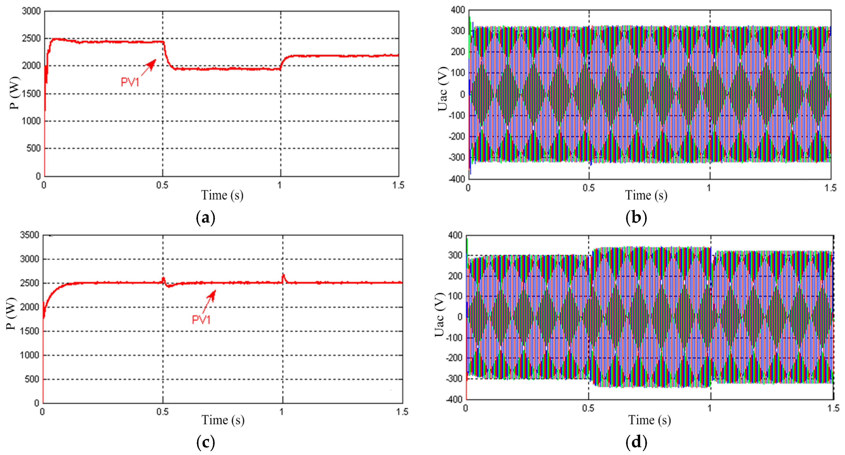
5.1. Case 1: Test of the Proposed Droop-1 Control Strategy for Photovoltaic

To verify the performance of the proposed Droop-1 control, the simulation model and control scheme are established as shown in Figure 2 and Figure 4. The AC load decreases by about 0.5 kW at t = 0.5 s, and increases by about 0.2 kW at t = 1.0 s. Figure 9 shows the output active power and AC voltage waveforms of PV without Droop-1 control and with Droop-1 control, respectively. 
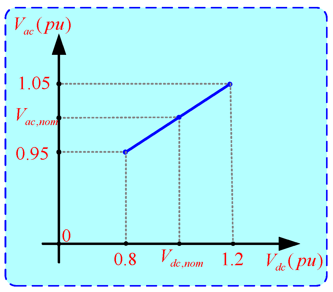
Figure 9a,b shows that the output power of PV varies with the load change, and that the voltage is almost same. When Droop-1 control is adopted, the acceptable voltage deviation (±5%) from its nominal value is highly utilized. From Figure 9c,d, PV always works at the maximum power tracking point subject to the slip load change. Thus, frequent power regulation is avoided, and the characteristic of PV is fully considered.

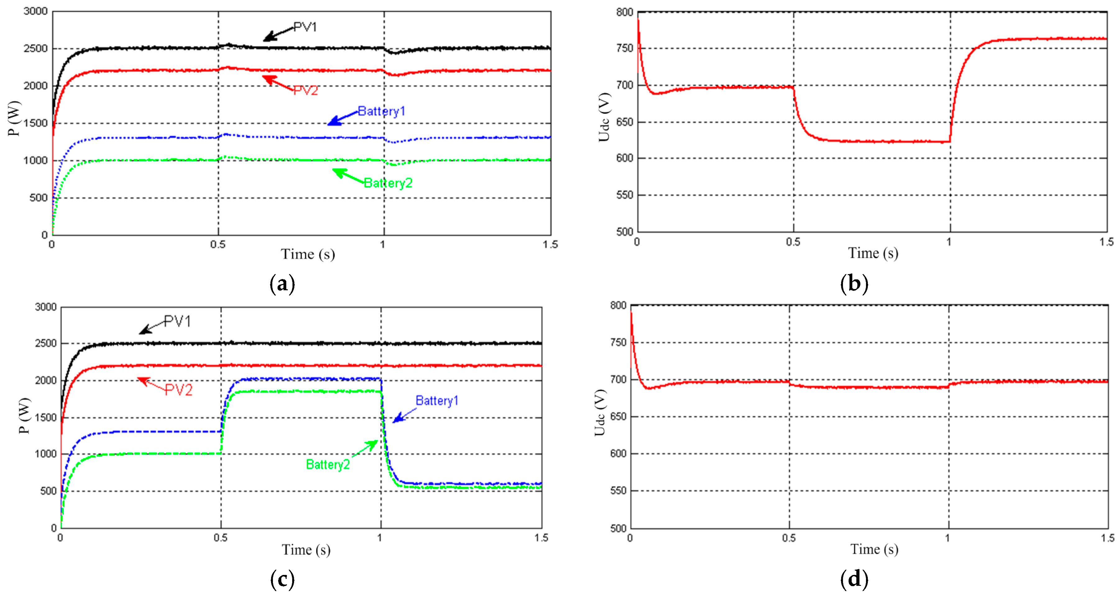
5.2. Case 2: Test of the Proposed Droop-2 Control Strategy for DC-Side Microgrid

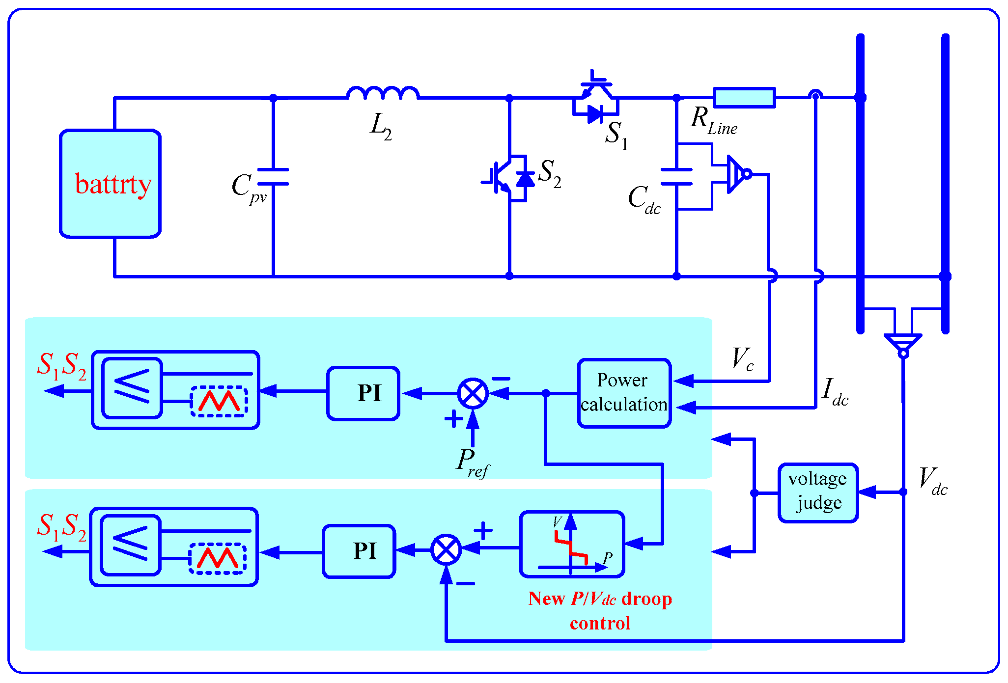
In this case, in order to test the performance of the proposed Droop-2 control method, the DC load increases by about 1.5 kW at t = 0.5 s, and decreases by about 2.7 kW at t = 1.0 s. Two PV generations (PV1 and PV2) on the DC-side operate in parallel with the MPPT control, and the proposed Droop-2 control method is performed on two battery units.
Figure 10a,b shows the output active power and DC bus voltage waveforms with the conventional constant power control method. There is quite a large DC bus voltage deviation (±10.7%) when the DC loads change. The obtained voltages exceed the voltage limits since no power flexibility is incorporated in the control. Therefore, the proposed Droop-2 control controller is included in the next simulation.
From Figure 10c,d, the Droop-2 controller forces the voltage closer to the nominal value of 0.7 kV. When the DC load increases at the time interval t [0.5, 1.0], the proposed Droop-2 control strategy detects the bus voltage, and the battery switches to droop control strategy in order to share the load. The detailed results are shown with VDC = 0.68 kV, PPV1 = 2.5 kW, PPV2 = 2.2 kW, Pb1 = 2.0 kW, and Pb2 = 1.8 kW. When the load decreases at the time interval t [1.0, 1.5], the results are obtained with VDC = 0.69 kV, PPV1 = 2.5 kW, PPV2 = 2.2 kW, Pb1 = 0.6 kW, and Pb2 = 0.5 kW, and the voltage limit violation is avoided. Therefore, the effectiveness of the proposed Droop-2 control method is verified.

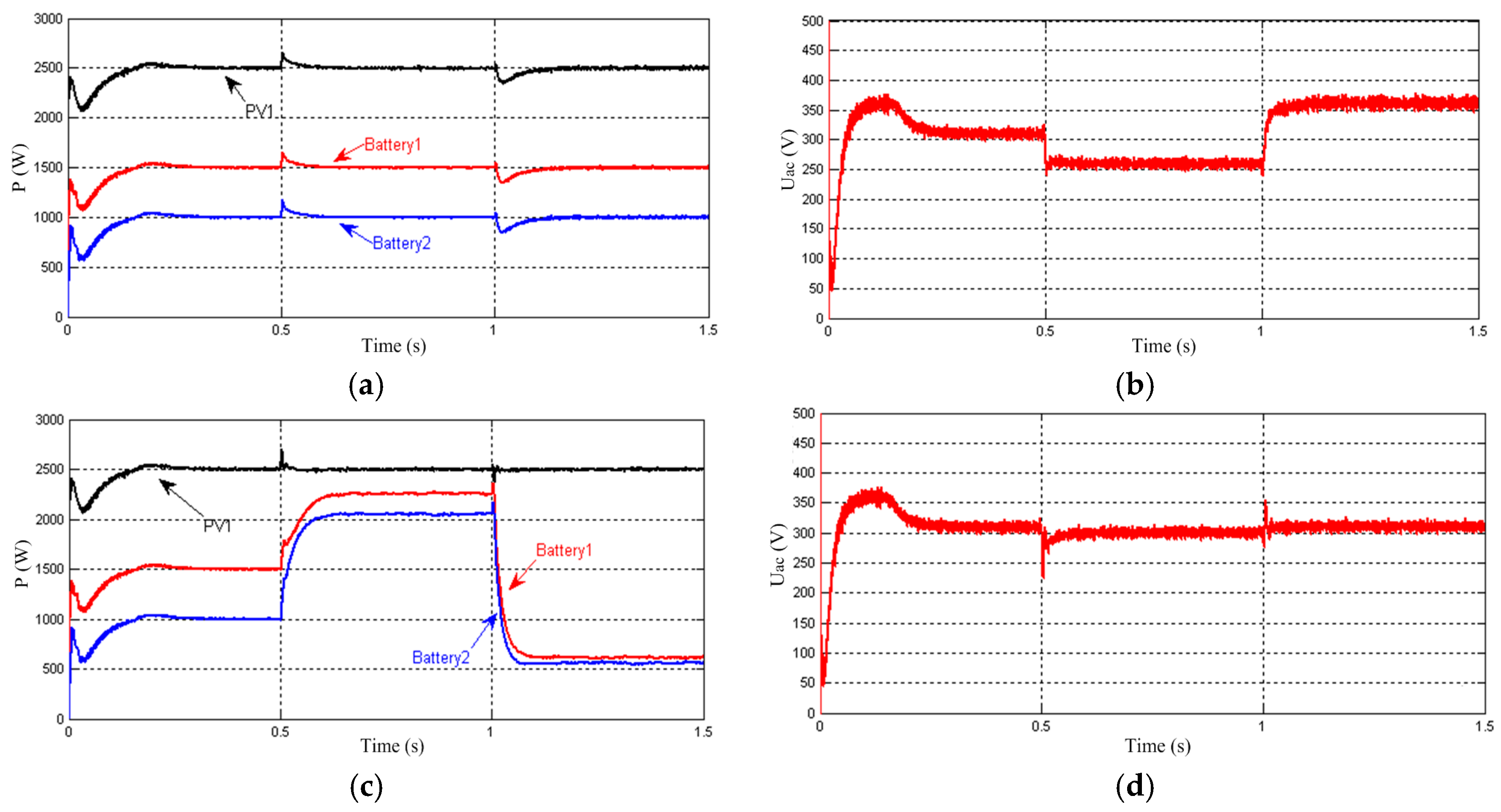
5.3. Case 3: Test of the Proposed Droop-1 Control Strategy and Droop-3 Control for AC-Side Microgrid

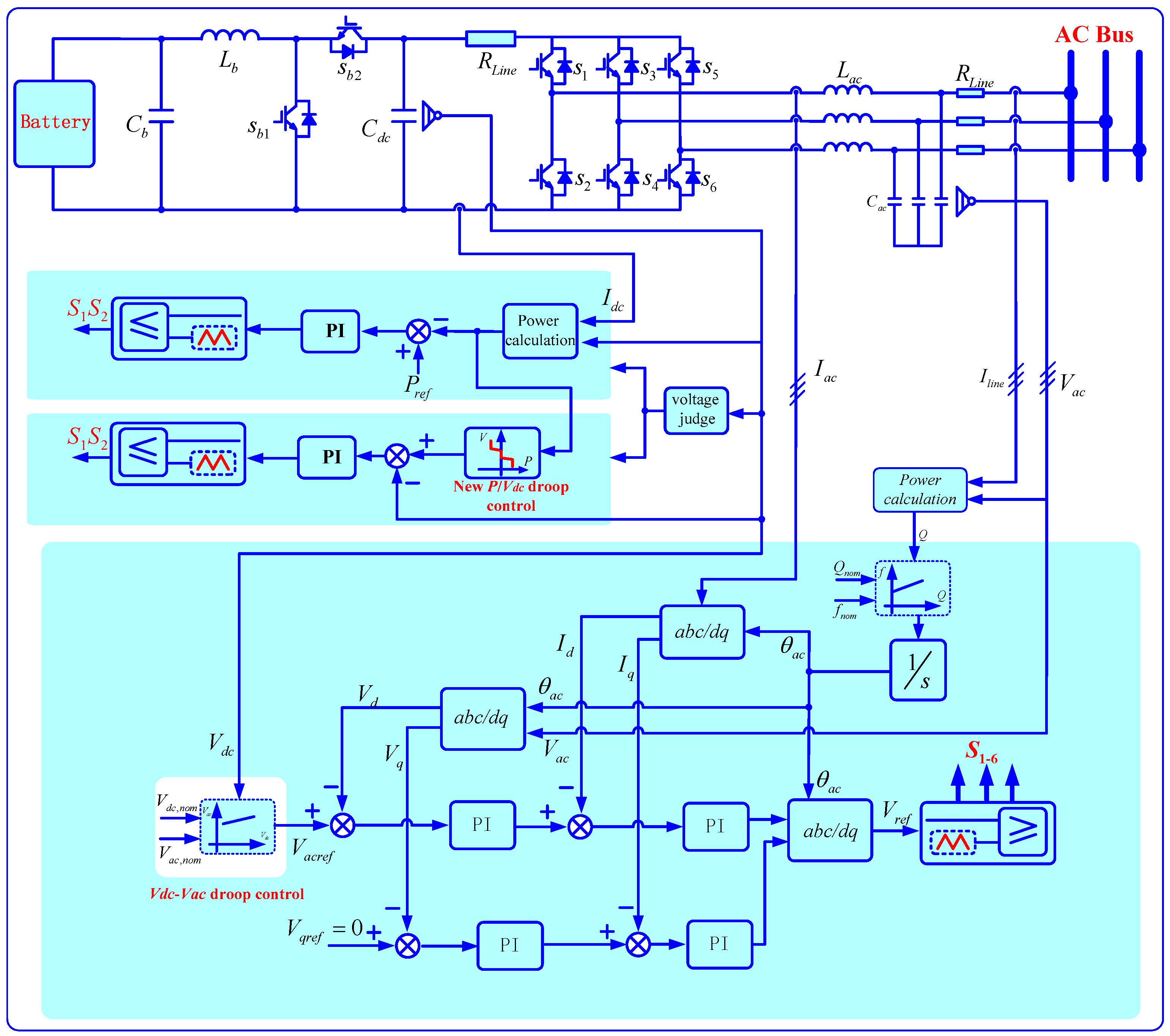
To test the performance of the proposed Droop-1 and Droop-3 control, the AC load increases by about 1.8 kW at t = 0.5 s, and decreases by about 2.2 kW at t = 1.0 s. The PV1 generation in AC-side adopts Droop-1 control, and the proposed Droop-3 control method is applied to two battery units in this case.
Figure 11a,c shows the output active power waveforms with the conventional constant power control method and the proposed Droop-1 and Droop-3 control strategies, respectively. Compared with Figure 11a,c reveals that PV1 generation keeps the constant power mode, while Batteries 3 and 4 operate in parallel to match changing the AC load. As can be seen in Figure 11d, the AC bus voltage nearly maintains its nominal value, while a great voltage deviation (±16%) occurs as shown in Figure 11b. Therefore, it is concluded that in the case of over-voltage or under-voltage, regulating P by the P/VDC droop control indeed benefits the microgrid control. It should be noted that when choosing a smaller constant-power band, the microgrid voltage would be closer to the nominal value.
From this case, it is concluded that the Droop-1 controller obtains a stable operation of the hybrid microgrid, avoids frequent power changes, and fully exploits the control capability of the power sources by setting the constant-power band. At the same time, Droop-3 control guarantees power sharing according to the ratings of the ES units and limits the voltage under no inter-unit communication.

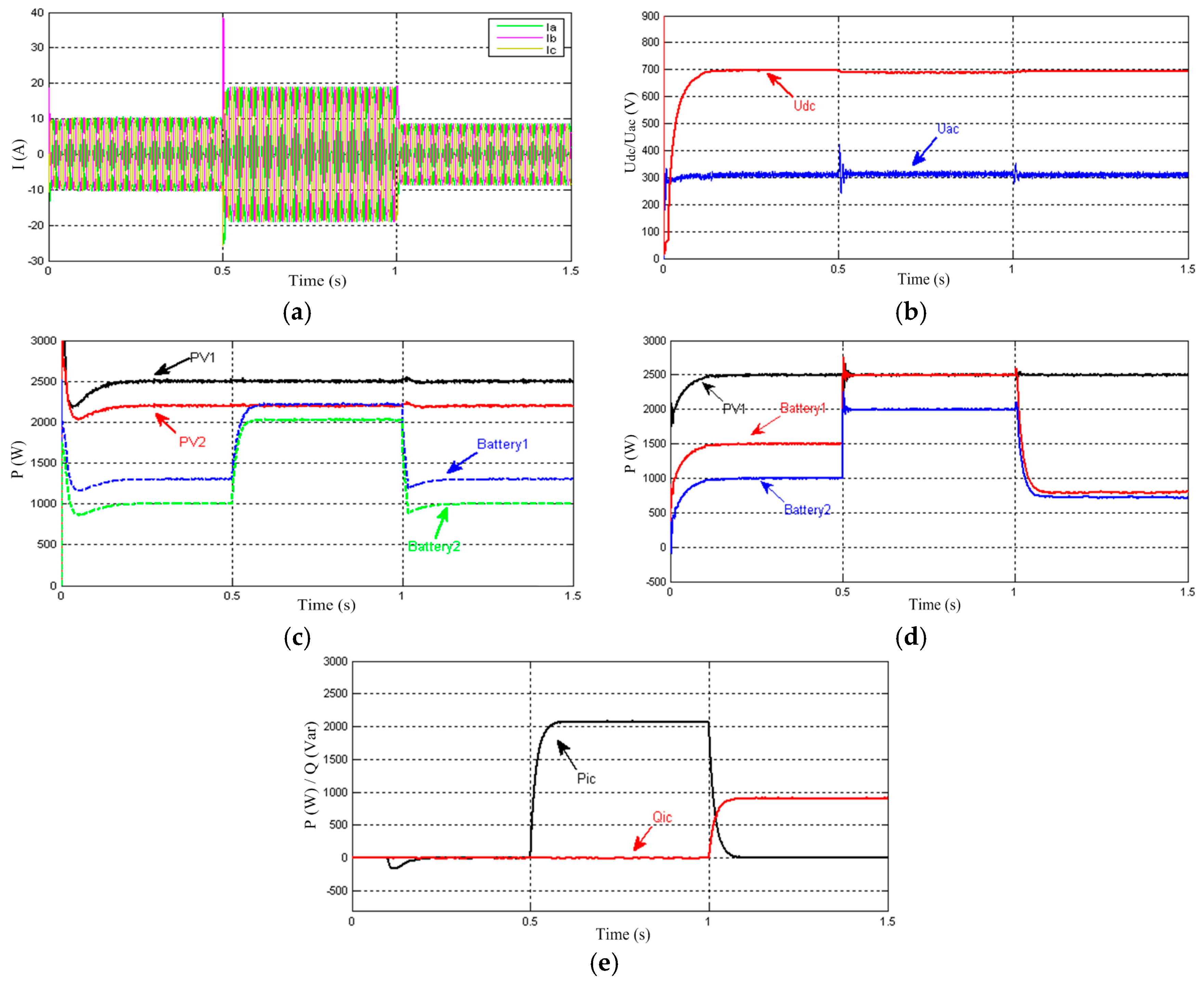
5.4. Case 4: Test of the Proposed Control Strategy for Interlinking Converter and Overall Hybrid Microgrid

To verify the overall system responses, the proposed control strategy of the IC is applied. The AC load increases by about 3.5 kW at t = 0.5 s, leading to an excess of the AC-side capacity. Furthermore, the active power on AC-side decreases about 4.5 kW, and reactive power increases by about 1.0 kVar at time t = 1.0 s. Notice that the DC load has remained constant.
Figure 12a,b shows the load current and the AC/DC bus voltage waveforms with the proposed control method. It can be seen that the bus voltages are close to the rated value. Then, the strong voltage regulation ability is obtained. The active power and reactive power of all units in hybrid system are shown in Figure 12c,d. At the first stage t [0, 0.5], all units operated with PPV1 = 2.5 kW, PPV2 = 2.2 kW, Pb1 = 1.3 kW, and Pb2 = 1.0 kW on the DC-side. The active power control mechanism of the IC is disabled, and thus operating losses are avoided. When the AC load changes at t = 0.5 s, exceeding the AC bus capacity, and the DC-side has power remaining, the IC is activated with the power transmission Pic = 2.0 kW, Qic = 0 kVar, PPV1 = 2.5 kW, PPV2 = 2.2 kW, Pb1 = 2.3 kW, and Pb2 = 2.0 kW on the DC-side. However, the AC-side PV1 controlled with the MPPT mode keeps constant output power, and the Batteries 3 and 4 with Droop-3 controller have reached the capacity limit. The detailed results are shown with PPV1 = 2.5 kW, Pb3 = 2.5 kW, Pb4 = 2.0 kW on the AC-side, as seen in Figure 12c,d. After t = 1.0 s, the active power is reduced to the capacity range of the AC-side so that the AC/DC sides can meet the load demand and the active power control of the IC is not enabled. As can be seen in Figure 12e, the transmitted power Pic is 0. However, as the AC microgrid cannot satisfy the reactive power demand, the reactive power control for the ICs is operated as STATCOM. So the transmitted reactive power Qic from DC-side is 1.0 kVar.
It is concluded that the IC is a key element of the AC/DC hybrid for energy transmission, which not only can realize the transfer of active power and maintain the power balance of a hybrid microgrid system, but also provide reactive power compensation and other functions.

6. Conclusions

This paper proposes an autonomous power flow control to coordinate distributed components of a hybrid microgrid, consisting of ES units, PV generators, and interlink converters. The modified Droop-1 control is presented for PV generators, which considers the specific characteristics of generation units and avoids output power changes. No communication for the primary control is required, and the allowable voltage deviation from its nominal value is effectively used.
Furthermore, to avoid voltage limit violation, a novel Droop-2 control strategy is implemented to DC-side storage. Results show that proper power sharing and supply-demand balancing in islanded microgrids are achieved without communication. Moreover, the combination (Droop-3) of two control principles is introduced in order to obtain the advantages of both.
As a key element of a hybrid microgrid, an efficient control scheme of the IC is proposed with progressive energy flow tuning. Results show that the developed control can operate autonomously without fast communication links. It allows energy flow across the hybrid microgrid only when one of two sides is over-loaded, avoiding the operating losses. Furthermore, the IC can operate as a STATCOM to satisfy the reactive power demand. Finally, simulations results are provided to verify the effectiveness and performance of the proposed control strategy.

Acknowledgments

This work was supported by the National Natural Science Foundation of China under Grant No. 61573384 and the National High-tech R & D Program of China (863 Program) under Grant No. 2015AA050604.

Author Contributions

The paper was a collaborative effort between the authors. The authors contributed collectively to the theoretical analysis, modeling, simulation, and manuscript preparation.

Conflicts of Interest

The authors declare no conflict of interest.

References

  1. Yan, B.; Wang, B.; Zhu, L. A novel, stable, and economic power sharing scheme for an autonomous microgrid in the energy internet. Energies 2015, 8, 12741–12764. [Google Scholar] [CrossRef]
  2. Lim, Y.; Kim, H.M.; Kinoshita, T. Distributed load-shedding system for agent-based autonomous microgrid operations. Energies 2014, 7, 385–401. [Google Scholar] [CrossRef]
  3. Molderink, A.; Bakker, V.; Bosman, M.; Hurink, L.; Smit, G.J.M. Management and control of domestic smart grid technology. IEEE Trans. Smart Grid 2010, 1, 109–119. [Google Scholar] [CrossRef]
  4. Moslehi, K.; Kumar, R. A reliability perspective of the smart grid. IEEE Trans. Smart Grid 2010, 1, 57–64. [Google Scholar] [CrossRef]
  5. Gu, W.; Liu, W.; Wu, Z.; Zhao, B.; Chen, W. Cooperative control to enhance the frequency stability of islanded microgrids with DFIG-SMES. Energies 2013, 6, 3951–3971. [Google Scholar] [CrossRef]
  6. Xu, Z.; Yang, P.; Zeng, Z.; Peng, J.; Zhao, Z. Black start strategy for PV-ESS multi-microgrids with three-phase/single-phase architecture. Energies 2016, 9, 372. [Google Scholar] [CrossRef]
  7. Patterson, M.; Macia, N.F.; Kannan, A.M. Hybrid microgrid model based on solar photovoltaic battery fuel cell system for intermittent load applications. IEEE Trans. Energy Convers. 2015, 30, 359–366. [Google Scholar] [CrossRef]
  8. Alobeidli, K.A.; Syed, M.H.; El-Moursi, M.S. Novel coordinated voltage control for hybrid micro-grid with islanding capability. IEEE Trans. Smart Grid 2015, 6, 1116–1127. [Google Scholar] [CrossRef]
  9. Rocabert, J.; Luna, A.; Blaabjerg, F.; Rodriguez, P. Control of power converters in AC microgrids. IEEE Trans. Power Electron. 2012, 27, 4734–4749. [Google Scholar] [CrossRef]
  10. Hajizadeh, A.; Golkar, M.A. Intelligent power management strategy of hybrid distributed generation system. Int. J. Electr. Power Energy Syst. 2007, 29, 783–795. [Google Scholar] [CrossRef]
  11. Xiao, H.; Luo, A.; Shuai, Z. An improved control method for multiple bidirectional power converters in hybrid AC/DC microgrid. IEEE Trans. Smart Grid 2016, 7, 340–347. [Google Scholar] [CrossRef]
  12. Baran, M.E.; Mahajan, N.R. DC distribution for industrial systems: Opportunities and challenges. IEEE Trans. Ind. Appl. 2003, 39, 1596–1601. [Google Scholar] [CrossRef]
  13. Salomonsson, D.; Sannino, A. Low-voltage DC distribution system for commercial power systems with sensitive electronic loads. IEEE Trans. Power Deliv. 2007, 22, 1620–1627. [Google Scholar] [CrossRef]
  14. Dursun, E.; Kilic, O. Comparative evaluation of different power management strategies of a stand-alone PV/Wind/PEMFC hybrid power system. Int. J. Electr. Power Energy Syst. 2012, 34, 81–89. [Google Scholar] [CrossRef]
  15. Loh, P.C.; Ding, L.; Yi, K.C.; Blaabjerg, F. Autonomous operation of hybrid microgrid with AC and DC subgrids. IEEE Trans. Power Electron. 2013, 28, 2214–2223. [Google Scholar] [CrossRef]
  16. Xu, L.; Chen, D. Control and operation of a DC microgrid with variable generation and energy storage. IEEE Trans. Power Deliv. 2011, 26, 2513–2522. [Google Scholar] [CrossRef]
  17. Lai, C.M.; Yang, M.J. A high-gain three-port power converter with fuel cell, battery sources and stacked output for hybrid electric vehicles and DC microgrids. Energies 2016, 9, 180. [Google Scholar] [CrossRef]
  18. Farzam, N.; Li, Y.W. Overview of power management strategies of hybrid AC/DC microgrid. IEEE Trans. Power Electron. 2015, 30, 7072–7089. [Google Scholar]
  19. Mohammadia, M.; Nafar, M. Fuzzy sliding-mode based control (FSMC) approach of hybrid micro-grid in power distribution systems. Int. J. Electr. Power Energy Syst. 2013, 51, 232–242. [Google Scholar] [CrossRef]
  20. Poh, C.L.; Ding, L.; Yi, K.C.; Frede, B. Hybrid AC-DC microgrids with energy storages and progressive energy flow tuning. IEEE Trans. Power Electron. 2013, 28, 1533–1543. [Google Scholar]
  21. Tan, X.; Li, Q.; Wang, H. Advances and trends of energy storage technology in Microgrid. Int. J. Electr. Power Energy Syst. 2013, 44, 179–191. [Google Scholar] [CrossRef]
  22. Hajizadeh, A.; Golkar, M.A. Control of hybrid fuel cell/energy storage distributed generation system against voltage sag. Int. J. Electr. Power Energy Syst. 2010, 32, 488–497. [Google Scholar] [CrossRef]
  23. Noroozian, R.; Abedi, M.; Gharehpetianb, G.B.; Hosseini, S.H. Distributed resources and DC distribution system combination for high power quality. Int. J. Electr. Power Energy Syst. 2010, 32, 769–781. [Google Scholar] [CrossRef]
  24. Holtz, J.; Lotzkat, W.; Werner, K.H. A high power multitransistor inverter uninterruptible power supply system. IEEE Trans Power Electron. 1998, 3, 278–285. [Google Scholar] [CrossRef]
  25. Radwan, A.A.A.; Mohamed, Y.A.R.I. Networked control and power management of AC/DC hybrid microgrids. IEEE Syst. J. 2014, PP, 1–12. [Google Scholar] [CrossRef]
  26. Lu, X.; Guerrero, J.M.; Sun, K.; Juan, C.V.; Remus, T.; Huang, L. Hierarchical control of parallel AC-DC converter interfaces for hybrid microgrids. IEEE Trans. Smart Grid 2014, 5, 683–692. [Google Scholar] [CrossRef]
  27. Poh, C.L.; Li, D.; Chai, Y.K.; Blaabjerg, F. Autonomous control of interlinking converter with energy storage in hybrid AC-DC microgrid. IEEE Trans. Ind. Appl. 2013, 49, 1374–1382. [Google Scholar]
  28. Wang, P.; Jin, C.; Zhu, D.; Tang, Y.; Loh, P.C.; Choo, F.H. Distributed control for autonomous operation of a three-port AC/DC/DS hybrid microgrid. IEEE Trans. Ind. Electron. 2015, 62, 1279–1290. [Google Scholar] [CrossRef]
  29. Liu, X.; Wang, P.; Loh, P.C. A hybrid AC/DC microgrid and its coordination control. IEEE Trans. Smart Grid 2011, 2, 278–286. [Google Scholar]
  30. Vandoorn, T.L.; Meersman, B.; Degroote, L.; Renders, B.; Vandevelde, L. A control strategy for islanded microgrids with DC-link voltage control. IEEE Trans. Power Deliv. 2011, 26, 703–713. [Google Scholar] [CrossRef]
  31. Vandoorn, T.L.; Meersman, B.; Jeroen, D.M.; Vandevelde, L. Analogy between conventional grid control and islanded microgrid control based on a global DC-link voltage droop. IEEE Trans. Power Deliv. 2012, 27, 1405–1414. [Google Scholar] [CrossRef] [Green Version]
  32. Vandoorn, T.L.; Jeroen, D.M.; Meersman, B.; Josep, M.G.; Vandevelde, L. Voltage-based control of a smart transformer in a microgrid. IEEE Trans. Ind. Electron. 2013, 60, 1291–1305. [Google Scholar] [CrossRef] [Green Version]
  33. Li, J.; Wei, W.; Xiang, J. A simple sizing algorithm for stand-alone PV/wind/battery hybrid microgrids. Energies 2012, 5, 5307–5323. [Google Scholar] [CrossRef]
  34. Song, N.O.; Lee, J.H.; Kim, H.M.; Im, Y.H.; Lee, J.Y. Optimal energy management of multi-microgrids with sequentially coordinated operations. Energies 2015, 8, 8371–8390. [Google Scholar] [CrossRef]
  35. Moradi, M.H.; Eskandari, M.; Hosseinian, S.M. Cooperative control strategy of energy storage systems and micro sources for stabilizing microgrids in different operation modes. Int. J. Electr. Power Energy Syst. 2016, 78, 390–400. [Google Scholar] [CrossRef]
  36. Mohammadi, F.D.; Feliachi, A. Adaptive price management in hybrid microgrid in presence of PV and battery energy storage system. In Proceedings of the 2014 IEEE PES T&D Conference and Exposition, Chicago, IL, USA, 14–17 April 2014.
  37. Guerrero, J.M.; Matas, J.; De Vicuña, L.G. Decentralized control for parallel operation of distributed generation inverters using resistive output impedance. IEEE Trans. Ind. Electron. 2007, 54, 994–1004. [Google Scholar] [CrossRef]
  38. Mastromauro, R.A.; Liserre, M.; Dell’Aquila, A. Control issues in single-stage photovoltaic systems: MPPT, current and voltage control. IEEE Trans. Ind. Inform. 2012, 8, 241–254. [Google Scholar] [CrossRef]
  39. Esram, T.; Chapman, P.L. Comparison of photovoltaic array maximum power point tracking techniques. IEEE Trans. Energy Convers. 2007, 22, 439–449. [Google Scholar] [CrossRef]
Figure 1. Hybrid microgrid configuration with energy storage (ES) and photovoltaic (PV) units.
Energies 09 00651 g001
Figure 2. Microgrid architecture for one distributed generation (DG).
Energies 09 00651 g002
Figure 3. Schematic diagram of the new VDC/VAC droop.
Energies 09 00651 g003
Figure 4. The overall scheme of the alternating current (AC)-side PV generator in hybrid microgrid.
Energies 09 00651 g004
Figure 5. Schematic diagram of the proposed P/VDC droop control.
Energies 09 00651 g005
Figure 6. The overall scheme of the ES unit on the direct current (DC)-side.
Energies 09 00651 g006
Figure 7. The overall scheme of the AC-side ES unit in hybrid microgrid.
Energies 09 00651 g007
Figure 8. The final control diagram of the interlinking converter (IC).
Energies 09 00651 g008
Figure 9. Simulated results of case 1: (a) output power without Droop-1 control; (b) AC bus voltage without Droop-1 control; (c) output power with Droop-1 control; and (d) AC bus voltage with Droop-1 control.
Energies 09 00651 g009
Figure 10. Simulated results of case 2: (a) output power without Droop-2 control; (b) DC bus voltage without Droop-2 control; (c) output power with Droop-2 control; and (d) DC bus voltage with Droop-2 control.
Energies 09 00651 g010
Figure 11. Simulated results of case 3: (a) output active power without Droop-1 and Droop-3 control; (b) AC bus phase voltage without Droop-1 and Droop-3 control; (c) output active power with proposed Droop-1 and Droop-3 control; and (d) AC bus phase voltage with proposed Droop-1 and Droop-3 control.
Energies 09 00651 g011
Figure 12. Simulated results of case 4: (a) the AC load varying current waveform; (b) DC and AC bus voltage; (c) output active power of units on the DC-side; and (d) output active power of units on the AC-side; (e) output active power and reactive power of IC.
Energies 09 00651 g012
Table 1. Parameters of the hybrid system.
ParametersValues
Hybrid system capacity20 kW
Rated DC bus voltage700 V
PV1/PV2 Rated Power (DC-side)6 kW/6 kW
Battery b1 rated voltage/capacity (DC-side)120 V/2.5 kW/120 Ah
Battery b2 rated voltage/capacity (DC-side)120 V/2.0 kW/100 Ah
DC loads7 kW
Rated AC bus voltage380 V/50 Hz
PV1 Rated Power (AC-side)3 kW
Battery b3 rated voltage/capacity (AC-side)120 V/2.5 kW/120 Ah
Battery b4 rated voltage/capacity (AC-side)120 V/2.0 kW/100 Ah
AC loads5 kW/1 kVar

