Article

Ceramic-Based 4D Components: Additive Manufacturing (AM) of Ceramic-Based Functionally Graded Materials (FGM) by Thermoplastic 3D Printing (T3DP)

1
Processes and Components, Fraunhofer Institute for Ceramic Technologies and Systems (IKTS), 01277 Dresden, Germany
2
Fraunhofer Singapore, Singapore 639798, Singapore
*
Author to whom correspondence should be addressed.
Materials 2017, 10(12), 1368; https://doi.org/10.3390/ma10121368
Submission received: 10 October 2017 / Revised: 9 November 2017 / Accepted: 25 November 2017 / Published: 28 November 2017
(This article belongs to the Special Issue NextGen Materials for 3D Printing)

Abstract

:
In our study, we investigated the additive manufacturing (AM) of ceramic-based functionally graded materials (FGM) by the direct AM technology thermoplastic 3D printing (T3DP). Zirconia components with varying microstructures were additively manufactured by using thermoplastic suspensions with different contents of pore-forming agents (PFA), which were co-sintered defect-free. Different materials were investigated concerning their suitability as PFA for the T3DP process. Diverse zirconia-based suspensions were prepared and used for the AM of single- and multi-material test components. All of the samples were sintered defect-free, and in the end, we could realize a brick wall-like component consisting of dense (<1% porosity) and porous (approx. 5% porosity) zirconia areas to combine different properties in one component. T3DP opens the door to the AM of further ceramic-based 4D components, such as multi-color, multi-material, or especially, multi-functional components.

1. Introduction

The term “4D printing” was initially used by Tibbits and Sheil [1] and describes a technology that was developed through a collaboration between The Self-Assembly Lab, Stratasys, and Autodesk to manufacture customizable smart materials. By using an additive manufacturing (AM) device, polymer multi-material components with the added capability of shape transformation from one state to another can be realized. This offers the possibility to include functionalities such as actuation, sensing, and material logic directly into the components [2]. Additively manufactured multi-material components can transform from any 1D strand or 2D surface into a 3D shape, or morph from one 3D shape into another. Using only water, heat, light, or another simple energy input, this technique offers adaptability and dynamic response for structures and systems of all sizes [2]. Khoo et al. conducted an overview of actual works on “4D printing” based on polymer and metallic materials [3]. Khare et al. presented different concepts and technologies to combine different materials on the atomic scale to realize components that can change their shape or operate as an actuator [4].
For ceramic components in particular, it is very challenging to realize such properties. The reason for this challenge is that a thermal treatment is necessary after the AM process to generate the ceramic properties. In order to obtain a multi-material composite, it is fundamental to successfully co-process and co-sinter the paired powders in the composite material. Since the sintering of the components is performed at the same temperature and atmosphere, it is a prerequisite for all of the materials to have a comparable sintering temperature and behavior (starting temperature of sintering, shrinkage behavior). To avoid critical mechanical stress during cooling, it is also important that the coefficient of thermal expansion of all the materials is approximately equal [5,6].
Nevertheless, it is possible to realize ceramic components with a variety of properties by realizing a graded microstructure or material gradients. These composites are called functionally graded materials (FGM) [7]. To achieve unprecedented properties of ceramic components, we combine the benefits of AM with the benefits of FGM to create “ceramic-based 4D materials”, which are manufactured additively and combine different properties and/or materials in one component after a co-sintering step.
In a FGM, the properties change gradually with position [7], which generates new fields of application. The combination of two or more materials in graded microstructures such as ceramic–metal composites results in innovative, multi-functional property combinations, such as hard and ductile, electrically or thermally conductive and insulating, magnetic and nonmagnetic [8]. Such materials could be used to create conceivable applications in a variety of industrial and medical fields, such as for example, cutting tools, wear-resistant components, energy and fuel cell components, and bipolar surgical tools [9,10,11,12,13,14]. Figure 1 shows the metal–ceramic components for different applications manufactured at our group “Shaping” of the Fraunhofer IKTS (Institute for Ceramic Technologies and Systems) by two-component ceramic injection molding (2C-CIM) [14]. Furthermore, the manufacturing of two-color components is possible with 2C-CIM, which was demonstrated by Fraunhofer IKTS (FhG-IKTS) as well. (Figure 2).
Components with different porosities combine different properties in the gradient structure regarding thermal conductivity, heat capacity, density, mechanical strength, and elastic modulus, which results in improved thermal shock properties [15]. In the case of open porosity, it is possible to generate selective filters that are able to filtrate by tailored pore sizes in a complex or small single component. Figure 3 shows the SEM image of a cross-section of a sintered MgO–ZrO2 component with graded porosity, and Figure 4 shows the crack surface after a crack deflection during a bending test, which occurred due to the graded microstructure and varied Young’s modulus or rather stress distribution [8]. Both samples were manufactured at Fraunhofer IKTS.
AM technologies make it possible to produce components with extremely complex geometry that cannot be attained by any other shaping technique without the use of tools, because it is “the general term for those technologies that based on a geometrical representation creates physical objects by successive addition of material” [16]. For processing ceramic materials, the technical application of AM technologies has been limited so far. However, ceramics have been studied in AM processes ab initio, with the development of different AM technologies over the last 25 years [17,18]. All of the established AM technologies have also been tested for ceramic materials [19,20,21,22,23,24,25,26,27,28,29,30,31,32,33,34,35,36,37,38,39,40,41,42,43,44,45]. AM technologies can be classified according to the state of the material that is used—powder materials, liquid materials and solid materials [46,47]—or according to the kind of material deposition and solidification [48]. Lithography-based ceramic manufacturing (LCM) enables the AM of dense alumina (Figure 5 and Figure 6) and zirconia components with extraordinary complex geometries [24,25,26,49,50].
Several technologies are known for the production of FGM. There are very good overviews by Kieback et al. [7], Naebe et al. [51], and Moritz et al. [5]. Conventional shaping technologies can be used to produce FGM, such as powder pressing [52], slip casting [53,54], powder injection molding [55,56], tape casting [8,57,58,59]. A combination of conventional shaping technologies can also be used to produce FGM. One example is inmold labeling, which is a combination of tape casting and injection molding [60,61].
The first studies on the AM of ceramic-based FGM components were published about 20 years ago [62,63,64,65]. The multiphase jet solidification (MJS) technology, which is based on thermoplastic binder systems filled with high contents of ceramic particles, is nearly similar to the fused filament fabrication (FFF)/fused deposition modeling (FDM®) technology. A hot powder–binder mixture (feedstock) with suitable flow properties was deposited with an extrusion jet that moved in two dimensions. During cooling, the mixture solidified, and a free-standing body was formed. By using a two-piston construction combined with a small static mixing chamber, the powder composition was varied from layer to layer, and 3D graded SiC–TiC components could be formed [62,63].
Zhang et al. used laminated object manufacturing (LOM) to manufacture TiC–Ni FGMs. Green tapes with different compositions were produced, cut by a laser, stacked, and laminated [64].
Cesarano, J. III et al. already demonstrated in 1998 that a multi-material application is feasible with robocasting. For example, in addition to alumina components with different geometries (dense or porous), alumina/TiCuSil composite could also be realized [65].
Polsakiewicz and Kollenberg presented the AM of alumina-based multi-material components by binder jetting [45,66]. Ceramic or metal powders were dispersed in inks and selectively deposited in a ceramic powder bed.
Another approach is the functionalization of additively manufactured and sintered ceramic components subsequent to their generation. Figure 7 shows an alumina component manufactured by lithography-based ceramic manufacturing (LCM) that was sintered at 1600 °C and subsequently functionalized with electrically conductive heater structures by aerosol printing [5].
Direct AM technologies are more suitable for the AM of multi-material components than indirect AM technologies because of the selective deposition of the used material. The latter are based on the selective solidification of material deposited all over the entire layer. Therefore, the areas that have not been solidified are occupied by non-solidified material, which have to be removed before a second material can be deposited in these areas. Using direct AM technologies, a second material and further ones can be deposited directly beside the already deposited and solidified first material.
In our study, we investigated the AM of ceramic-based FGM by thermoplastic 3D printing (T3DP), which is a direct AM technology. Zirconia components with varying microstructures were additively manufactured by using thermoplastic suspensions with different contents of pore-forming agents (PFA), and were co-sintered defect-free.

2. Experimental

2.1. Thermoplastic 3D-Printing

T3DP is based on the selective deposition of particle-filled thermoplastic suspensions not over the entire surface, but instead only at the required spots [67]. Different suspensions can be deposited beside each other in each single layer, and bulk material as well as property gradients can be realized within the additively manufactured green components [67,68,69]. The solidification takes place almost independently of the physical properties of the used powders, so even hard metal components can be manufactured [70].
A special device was developed in Vermes, Germany that combines several supply containers and mechanical and electronic micro dispensing units (Figure 8). Hence, it could be used for the spatially resolved deposition of different materials, including supporting structures, in the same component. The micro dispensing units work with a nozzle orifice diameter of 160 μm. A piezo-driven hard metal piston moves up and down in the nozzle chamber to jet single droplets instead of filaments, which are deposited with extruder-like systems [71,72]. In our study, we used a maximum frequency of 100 Hz, but a frequency up to 3000 Hz is possible with the used system.

2.2. Used Materials

For the ceramic material, yttria-stabilized zirconia powders TZ-3Y-E by Tosoh Corporation of Japan (Tokyo, Japan) were used.
Three different materials were investigated concerning their behavior as PFAs. The main focus here was on the need for the PFA particles’ diameter to be much smaller than the nozzle orifice diameter of the micro dispensing system (160 μm); in particular, a particle diameter of 25 μm has proven applicable in previous experiments. In addition, the melting temperature of the PFA material should be higher than the melting temperature of the binder systems’ components to avoid undesired pore formation by the heating during processing, as well as inhomogeneities during the printing. ARBOCEL UFC100 of the company J. Rettenmaier Söhne GmbH + Co KG (Rosenberg, Germany) is a cellulose powder based on cellulose fibers with an average particle size of 6–12 μm. The decomposition temperature of this material is about 200 °C, and corresponds to the decomposition temperature of a second polysaccharide (PS) powder (starch) with a rounder shape and a maximum diameter below 25 μm. CERETAN MA 7008 (Münzing Chemie GmbH, Abstatt, Germany) is an amide of a carboxylic acid with a decomposition temperature of about 150 °C and a d99 of 8 μm. It was selected to investigate its suitability as a PFA in spite of the significantly lower decomposition temperature.

2.3. Feedstock Preparation

The different zirconia suspensions were prepared by dispersing the powder together with the PFA in a thermoplastic binder system based on a mixture of molten paraffin and beeswax. The dispersion and homogenization took place in a heatable dissolver (Dissolver DISPERMAT CA 20-C, VMA-Getzmann GmbH, Reichshof, Germany) by stirring for 4 h. Suspensions with 36 vol.-% and 40 vol.-% were prepared.
The content of the PFA was varied for each material. Table 1 summarizes the composition of the different thermoplastic suspensions.

2.4. Preparation of Single- and Multi-Material Test Components

The test samples were additively manufactured by using micro dispensing systems from Vermes, Germany. Four of them were mounted on our xyz-laboratory rig, which can operate alternately. In case of multi-material printing two dispensing units were used simultaneously.
The dispensing parameters had to be adjusted for each suspension due to their different rheological behaviors. Based on experience from previous experiments, the dispensing parameters were chosen to obtain a reproducible favorable droplet shape (small diameter, roundness) and avoid different adverse events such as occurring satellite droplets, adherent material on the nozzle orifice, trapped air, and incomplete fusion between adjacent droplets [72]. The deposition of the droplets had a frequency of up to 100 Hz, and the axes moved with a maximal velocity of 50 mm/s.
The green samples were debinded in a powder bed at a very low heating rate, in a first step under air atmosphere of up to 270 °C (heating rate 4 K/h), and then after removing the powder in a second step under air atmosphere of up to 900 °C (12 K/h). Afterwards, the components were sintered under air atmosphere at 1350 °C (3 K/min) for 2 h.

2.5. Characterization Methods

The particle size distribution of the utilized powders and PFA were measured by a laser diffraction method (Mastersizer 2000, Malvern Instruments Ltd., Malvern, UK). Electron scanning microscopy images have been used to characterize the shape of the particles.
To characterize the rheological behavior of the zirconia suspensions, a rheometer (Modular Compact Rheometer MCR 302; Anton Paar, Graz, Austria) that was adjustable between −25 to 200 °C with a plate/plate measuring system was used. The flow behavior was analyzed with an increasing shear rate (0–10,000 s−1) and at varying temperatures between 85–100 °C. The torque was measured and the viscosity calculated.
Field Emission Scanning Electron Microscopy (FESEM) images of the sintered samples have been utilized to evaluate the samples’ density and porosity. The FESEM images were converted into binary images by means of an open source software called ImageJ (1.47v, open source software, National Institutes of Health, USA), i.e., all of the pores were converted into black pixels, and the ceramic particles were converted into white pixels. In order to calculate the samples’ porosity, the software compared the number of the black and white pixels in a converted image of a samples’ cross-sections.
Additionally, the density was measured by Archimedes’ principle.

3. Results and Discussion

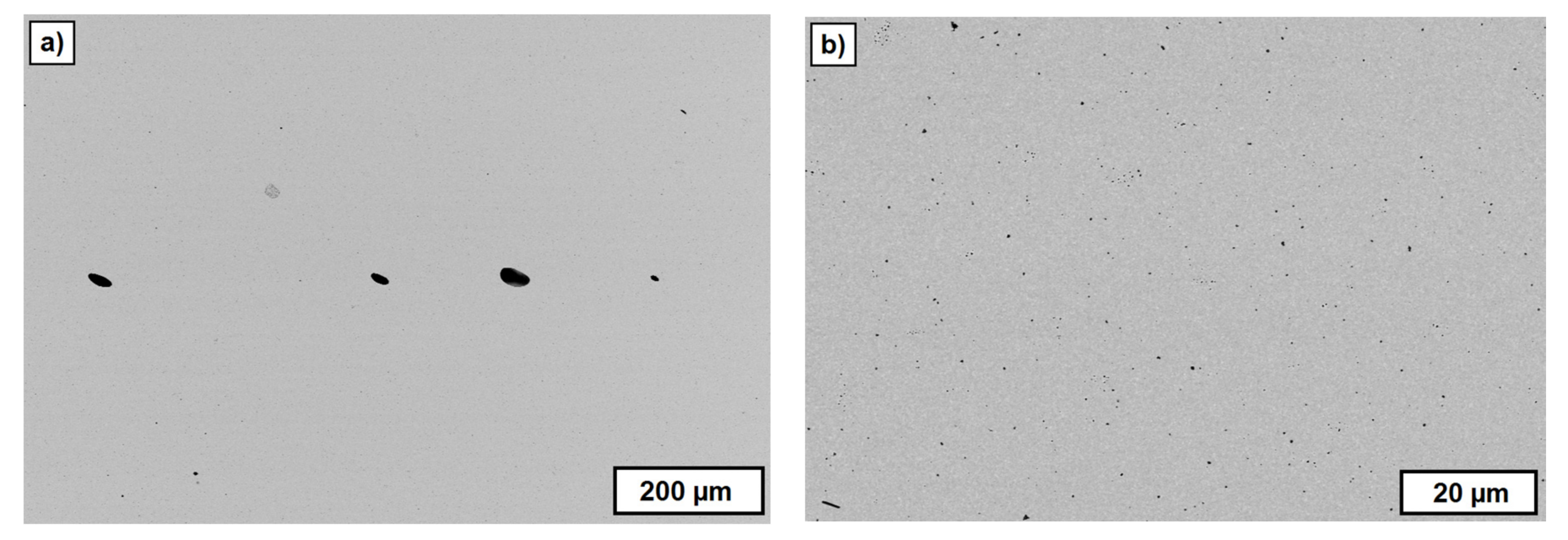
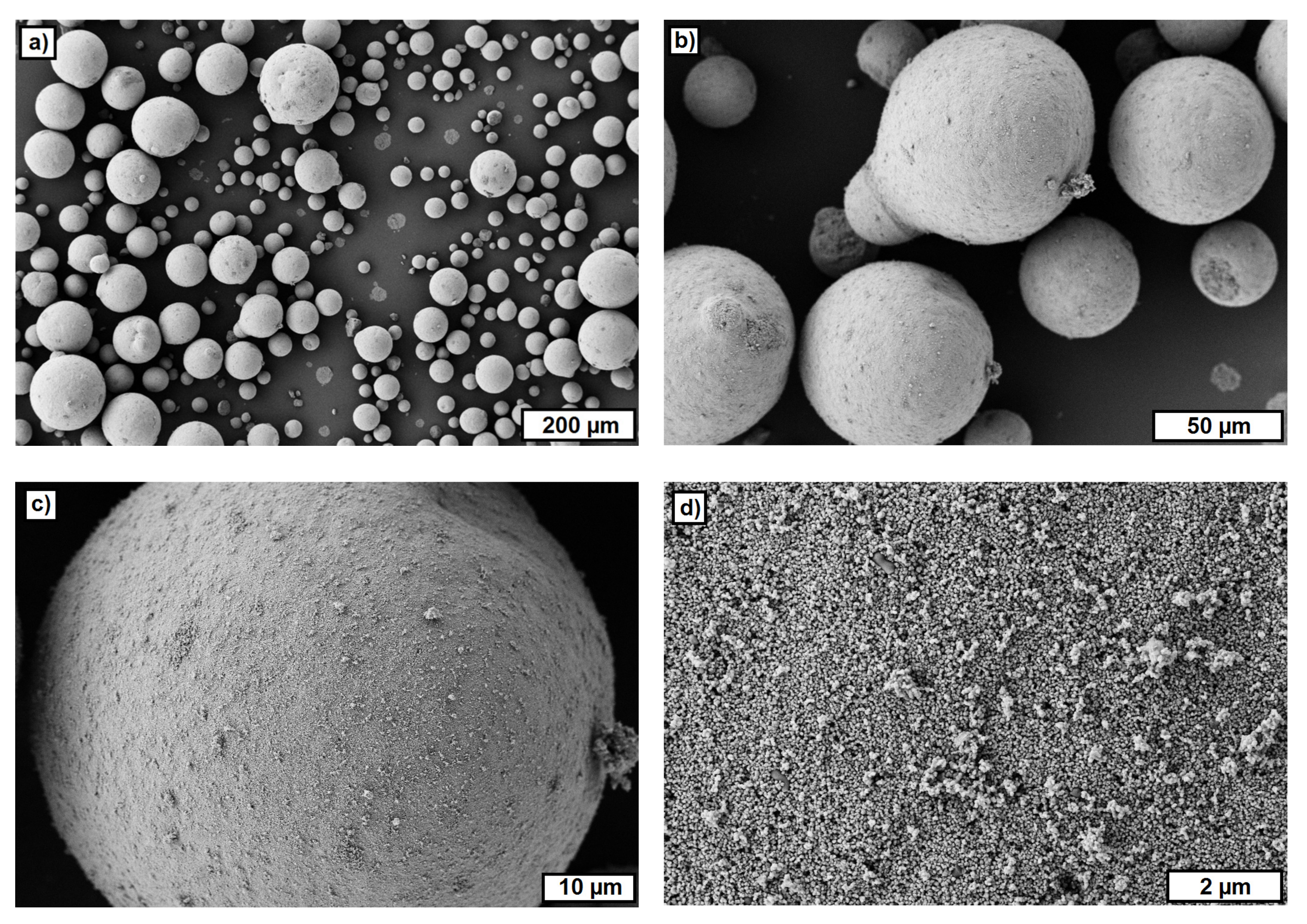
3.1. FESEM Studies of Used Materials

The measured average particle size (d50) of the zirconia powder was 0.37 μm by about one order of magnitude larger than the average particle size, as stated by Tosoh (d50 = 0.04 μm). FESEM images showed that the untreated powder consisted of very large granulates (diameter up to 100 μm) that were crushed during the ultrasonic treatment before the laser diffraction (Figure 9). Still, the applied treatment was insufficient regarding the deagglomeration of all the particles. However, during the feedstock preparation, very high shear forces were realized, which should deagglomerate all particles.
Figure 10 and Figure 11 show FESEM images of two materials used as a PFA. ARBOCEL UFC100 bases on cellulose fibers and the particles have a fiber fragments-like shape (Figure 10). The particles of the PS powder have a polyhedral-like shape (Figure 11). The particle size investigated on FESEM images varied between 5–20 μm.
The FESEM images of the used PFA materials provide an explanation for the content of the PFA, which could be realized in the different suspensions. A significantly higher content of PFA (up to 10 vol.-%) could be realized with the starch powder (polysaccharide). For the other two materials, the viscosity significantly increased for contents of more than 2 vol.-%. This probably results from the higher and rough surface of CERETAN MA 7008 and UFC 100 compared with the smooth surface of the starch powder.

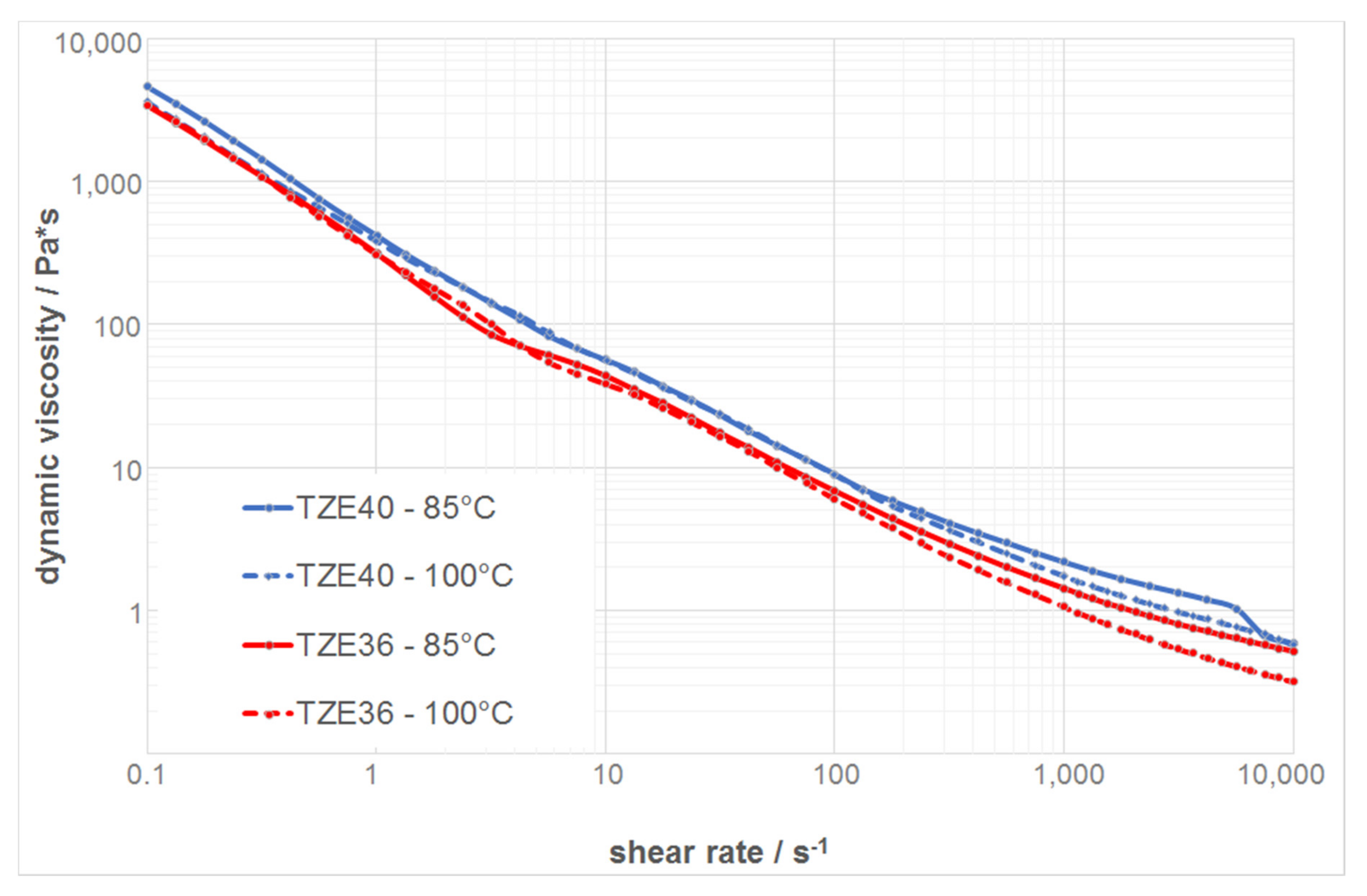
3.2. Rheological Behavior of the Thermoplastic Suspensions

The results of the rheological measurements of the two zirconia suspensions without any PFA are summarized in Figure 12. The dynamic viscosity is presented as a function of the shear rate in a double logarithmic plot, with a shear rate range between 0.1 and 10,000 s−1, where this range corresponds to the shear rate values at the nozzle for the dispensing parameters used. All of the suspensions show a shear thinning behavior at both temperatures. The dynamic viscosity increases with increasing solid content and decreasing temperature.
Figure 13 shows the dynamic viscosities as a function of the shear rate at a temperature of 100 °C for the different suspensions with and without PFA. The suspension without any PFA has the lowest viscosity, and by adding PFA, the viscosity increases due to the lower solid content compared with those loaded with PFA. However, all of the suspensions show a shear thinning behavior with a dynamic viscosity of 1 Pa·s or lower at a shear rate of 5000 s−1. Moreover, the course of the curves resembles those of previous experiments with printable feedstocks, which therefore can be utilized for T3DP [68]. Table 2 summarizes the measured viscosities of the suspensions at different shear rates and temperatures.

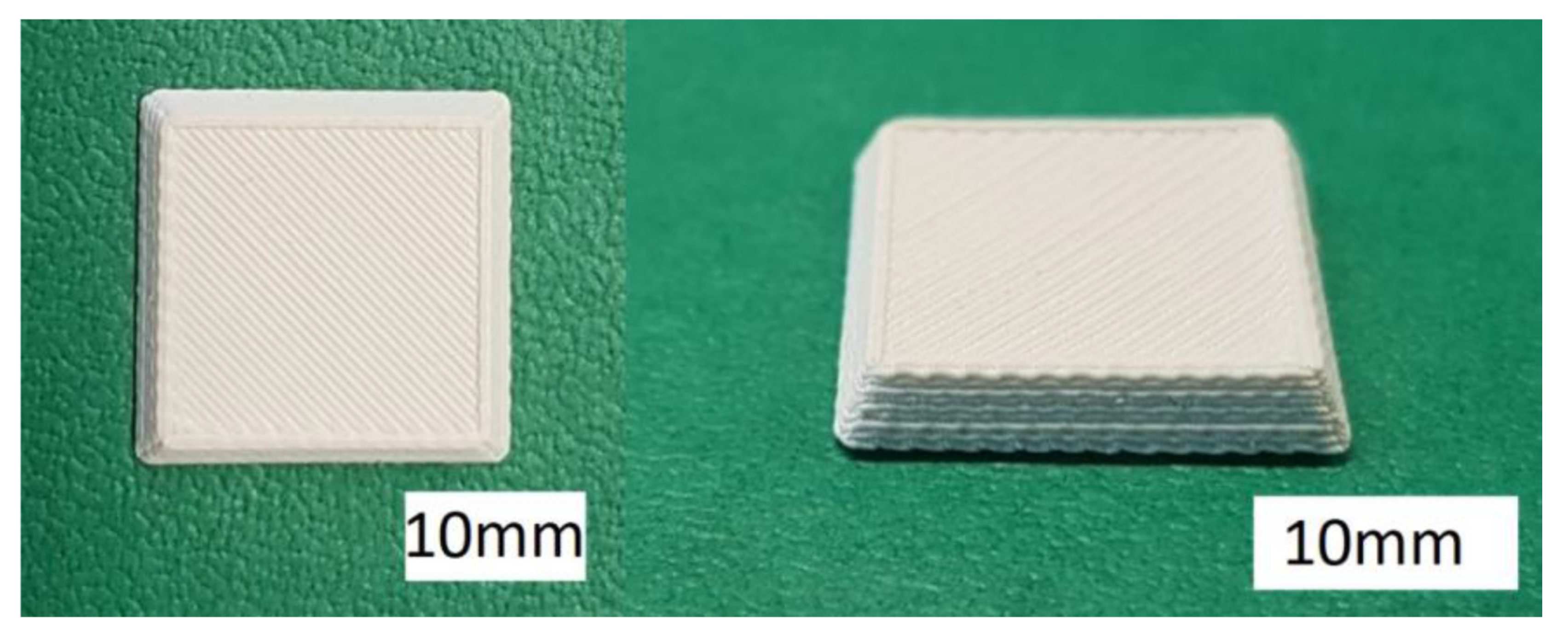
3.3. Single-Material Components

After a screening of the deposition parameters, it was possible to manufacture test components for each suspension. Figure 14 shows three views of a complex structure additively manufactured by T3DP with the zirconia suspension without a PFA. The shown test components were realized without a prerequisite utilization of any support structure; respectively, support material. After sintering, the wall thickness of this structure was less than 0.8 mm. The manufacturing time for the green component was approximately 30 min.
The FESEM images of the cross-section of sintered zirconia test components additively manufactured by T3DP with 36 vol.-% zirconia particles and without any PFA shown in Figure 15. The microstructure shows a homogeneous structure with a low content of porosity. By utilizing ImageJ and five different FESEM images, an average porosity of 0.11 ± 0.04% was calculated. With Archimedes’ principle, an average outer density of 5.90 ± 0.04 g/cm3 and an average inner density of 5.93 ± 0.05 g/cm3 was investigated for 14 test samples.
In addition, test samples of the suspensions with PFA were manufactured. Figure 16 shows the top and an angled view of a green sample including 5 vol.-% PS as PFA, for instance.
Figure 17 summarizes the FESEM images from regions of the inner core of the sintered single-material test components additively manufactured by T3DP with the suspensions that included 5 vol.-% PS (left) and 10 vol.-% PS (right) as PFA, taken at different magnifications. The images show a homogeneous distribution of the single pores, with a nearly round shape resulting from the polyhedron-like shape of the PS powder as PFA. The average porosities calculated with ImageJ on five images (200 × magnification, 2nd line in Figure 17) each are 5.02 ± 0.43% and 10.72 ± 0.87%, respectively. These correspond almost exactly to the content of added PFA in the suspensions (5 vol.-% and 10 vol.-%).
However, not every one of the used materials operated as a PFA. Figure 18 shows the FESEM images of sintered zirconia components additively manufactured by T3DP, and a suspension with 2 vol.-% of CERETAN MA 7008 as PFA. After sintering, only a few pores can be detected, which are located in the image in an almost horizontal row. These are most likely resulting from trapped air bubbles between two layers during the manufacturing process.
The decomposition temperature of CERETAN MA 7008 (about 150 °C) seems to be too low to be utilized as a PFA for T3DP. The material is removed during the first debinding step and probably due to a still lasting thermoplastic behavior of the suspension at this temperature, the rearrangement processes can occur driven by capillary forces. Subsequently, the remaining pores are eliminated during the final sintering step. This topic has to be investigated in further studies.

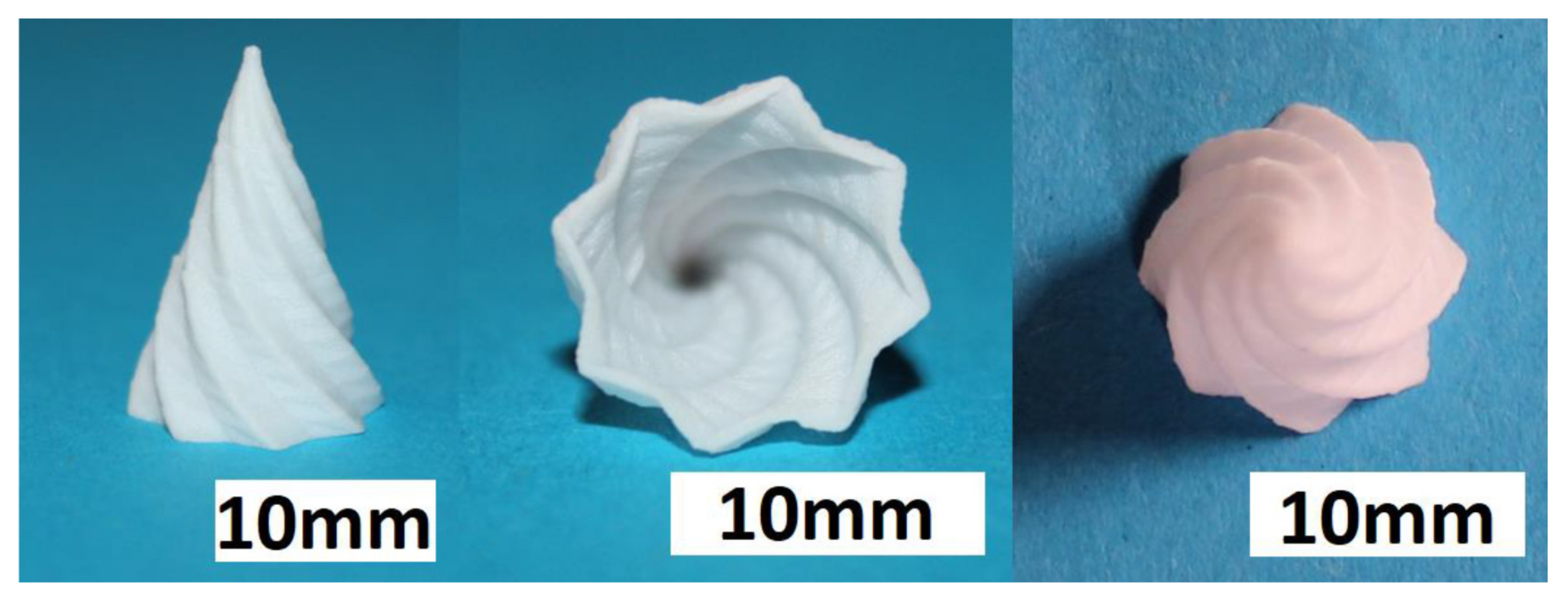
3.4. Ceramic-Based 4D Components

To demonstrate the additive manufacturing of zirconia-based 4D-components, we manufactured components with a brick wall design. Figure 19 shows a Computer Aided Design (CAD) drawing of the design. The brighter areas were manufactured with 5 vol.-% PS as the PFA, and the dark areas were manufactured with the pure zirconia suspension (36 vol.-% solid load, no PFA). As previously discussed, CERETAN MA 7008 was not suitable as PFA, and for ARBOCEL UFC100, only 2 vol.-% could be added to the suspension without significantly increasing the viscosity. The suspension with 5 vol.-% PS as PFA already formed a clearly detectable number of pores; therefore, it was considered sufficient for the mere demonstration of producing a 4D component. The resulting defect-free sintered components are shown in Figure 20.
FESEM images of cross-sections of these 4D components show clearly distinguishable areas at the interface between the two former suspensions (Figure 21). Thus, regardless of the drop-bound deposition of the material, the arrangement of the different microstructure can be realized very precisely.
To illustrate the difference in porosity, we placed the zirconia-based 4D components in front of a light spot (Figure 22). While the porous areas shine darker because of the light deflection and reflection, the denser areas show the opposite behavior by appearing more translucent. Figure 23 shows a light microscope image of the interface between the dense (lower left) and porous area (top and right) within the component.

4. Conclusions

In our study, we showed that it is possible to combine AM and FGM to create zirconia-based 4D components. We used the T3DP technology as a directly working AM technology to selectively deposit two different materials beside each other. This offers the possibility of combining suspensions with different contents of a PFA to realize components with dense and porous areas inside.
Different materials were investigated concerning their suitability as PFA for the T3DP process. Different zirconia-based suspensions were prepared and used for the AM of single- and multi-material test components. All of the samples were sintered defect-free, and in the end, we could realize a brick wall-like component consisting of dense (<1% porosity) and porous (approx. 5% porosity) zirconia areas to combine different properties in one component.
T3DP opens the door to the AM of further ceramic-based 4D components such as multi-color or multi-material components, which will be presented in further papers.

Acknowledgments

This project has received funding from the European Union’s Horizon 2020 Research and Innovation Programme under Grant Agreement No. 678503.

Author Contributions

Uwe Scheithauer, Steven Weingarten and Robert Johne conceived and designed the experiments; Steven Weingarten performed the experiments; Uwe Scheithauer, Steven Weingarten and Robert Johne analyzed the data; Eric Schwarzer, Johannes Abel, Hans-Jürgen Richter and Tassilo Moritz contributed reagents/materials/analysis tools; Tassilo Moritz and Alexander Michaelis supervised the thesis of Steven Weingarten and Robert Johne; Uwe Scheithauer, Steven Weingarten, Robert Johne and Eric Schwarzer wrote the paper.

Conflicts of Interest

The authors declare no conflict of interest.

References

  1. Tibbits, S.; Sheil, B. 4D printing: Multi-material shape change. Archit. Des. 2014, 84, 116–121. [Google Scholar] [CrossRef]
  2. Self-Assembly Lab, Stratasys Ltd. & Autodesk Inc. 4D Printing: Multi-Material Shape Change. Available online: http://www.selfassemblylab.net/ (accessed on 27 November 2017).
  3. Khoo, Z.X.; Teoh, J.E.M.; Liu, Y.; Chua, C.K.; Yang, S.; An, J.; Leong, K.F.; Yeong, W.Y. 3D printing of smart materials: A review on recent progress in 4D printing. Virtual Phys. Prototyp. 2015, 10, 103–122. [Google Scholar] [CrossRef]
  4. Khare, V.; Sonkaria, S.; Lee, G.Y.; Ahn, S.H.; Chu, W.S. From 3D to 4D printing—Design, material and fabrication for multi-functional multi-materials. Int. J. Precis. Eng. Manuf. 2017, 4, 291–299. [Google Scholar] [CrossRef]
  5. Moritz, T.; Scheithauer, U.; Mannschatz, M.; Ahlhelm, A.; Abel, J.; Schwarzer, E.; Pohl, M.; Müller-Köhn, A. Material- and process hybridization for multifunctional ceramic and glass components. Ceram. Appl. 2017, 5, 66–71. [Google Scholar]
  6. Scheithauer, U.; Slawik, T.; Schwarzer, E.; Richter, H.-J.; Moritz, T.; Michaelis, A. Additive manufacturing of metal-ceramic-composites by thermoplastic 3D-printing. J. Ceram. Sci. Technol. 2015, 6, 125–132. [Google Scholar] [CrossRef]
  7. Kieback, B.; Neubrand, A.; Riedel, H. Processing techniques for functionally graded materials. Mater. Sci. Eng. A 2003, 362, 81–106. [Google Scholar] [CrossRef]
  8. Scheithauer, U.; Schwarzer, E.; Slawik, T.; Richter, H.-J.; Moritz, T.; Michaelis, A. Functionally graded materials made by water-based multilayer technology. Refract. Worldforum 2016, 8, 95–101. [Google Scholar]
  9. Lee, H.C.; Potapova, Y.; Lee, D. A core-shell structured, metal-ceramic composite supported Ru catalyst for methane steam reforming. J. Power Sources 2012, 216, 256–260. [Google Scholar] [CrossRef]
  10. Molin, S.; Tolczyk, M.; Gazda, M.; Jasinski, P. Stainless steel/yttria stabilized zirconia composite supported solid oxide fuel cell. J. Fuel Cell Sci. Technol. 2011, 8, 051019. [Google Scholar] [CrossRef]
  11. Roberts, H.W.; Berzins, D.W.; Moore, B.K.; Charlton, D.G. Metal-ceramic alloys in dentistry: A review. J. Prosthodont. 2009, 18, 188–194. [Google Scholar] [CrossRef] [PubMed]
  12. Largiller, G.; Bouvard, D.; Carry, C.P.; Gabriel, A.; Müller, J.; Staab, C. Deformation and cracking during sintering of bimaterial components processed from ceramic and metal powder mixes. Part I: Experimental investigation. Mech. Mater. 2012, 53, 123–131. [Google Scholar] [CrossRef]
  13. Meulenberg, W.A.; Mertens, J.; Bram, M.; Buchkremer, H.-P.; Stöver, D. Graded porous TiO2 membranes for micro-filtration. J. Eur. Ceram. Soc. 2006, 26, 449–454. [Google Scholar] [CrossRef]
  14. Baumann, A.; Moritz, T.; Lenk, R. Multi component powder injection moulding of metal-ceramic-composites. In Proceedings of the Euro International Powder Metallurgy Congress and Exhibition 2009, Copenhagen, Denmark, 12–14 October 2009. [Google Scholar]
  15. Hein, J.; Scheithauer, U.; Haderk, K.; Kuna, M.; Michaelis, A. Prospect of a new generation of refractories made by ceramic multilayer technology. Refract. Man. 2012, 2, 91–95. [Google Scholar]
  16. ISO/ASTM 52900:2015(EN): Additive Manufacturing—General principles—Terminology; International Organization for Standardization: Berlin, Germany, 2015.
  17. Lakshminarayan, U.; Ogrydiziak, S.; Marcus, H.L. Selective laser sintering of ceramic materials. In Proceedings of the Solid Free-Form Symposium 1990, Austin, TX, USA, 6–8 August 1990; pp. 16–26. [Google Scholar]
  18. Lauder, A.; Cima, M.J.; Sachs, E.; Fan, T. Three dimensional printing: Surface finish and microstructure of rapid prototyped components. In Materials Research Society Symposium Proceedings; Materials Research Society: Warrendale, PA, USA, 1992; Volume 249, pp. 331–336. [Google Scholar]
  19. Pham-Gia, K.; Rossner, W.; Wessler, B.; Schäfer, M.; Schwarz, M. Rapid prototyping of high-density alumina ceramics using stereolithography. cfi/Ber. DKG 2006, 83, 36–40. [Google Scholar]
  20. Chartier, T.; Duterte, C.; Delhote, N.; Baillargeat, D.; Verdeyme, S.; Delage, C.; Chaput, C.J. Fabrication of millimeter wave components via ceramic stereo- and microstereolithography processes. J. Am. Ceram. Soc. 2008, 91, 2469–2474. [Google Scholar] [CrossRef]
  21. Griffith, M.L.; Halloran, J.W. Freeform fabrication of ceramics via stereolithography. J. Am. Ceram. Soc. 1996, 79, 2601–2608. [Google Scholar] [CrossRef]
  22. Licciulli, A.; Corcione, C.E.; Greco, A.; Amicarelli, V.; Maffezzoli, A. Laser stereolithography of ZrO2 toughened Al2O3. J. Eur. Ceram. Soc. 2005, 25, 1581–1589. [Google Scholar] [CrossRef]
  23. De Hazan, Y.; Thänert, M.; Trunec, M.; Misak, J. Robotic deposition of 3d nanocomposite and ceramic fiber architectures via UV curable colloidal inks. J. Eur. Ceram. Soc. 2012, 32, 1187–1198. [Google Scholar] [CrossRef]
  24. Felzmann, R.; Gruber, S.; Mitteramskogler, G.; Tesavibul, P.; Boccaccini, A.R.; Liska, R.; Stampfl, J. Lithography-based additive manufacturing of cellular ceramic structures. Adv. Eng. Mater. 2012, 14, 1052–1058. [Google Scholar] [CrossRef]
  25. Fischer, U.K.; Moszner, N.; Rheinberger, V.; Wachter, W.; Homa, J.; Längle, W. Lichthärtende Keramikschlicker für die Stereolithographische Herstellung von Hochfesten Keramiken (Light Curing Ceramic Suspensions for Stereolithography of High-Strength Ceramics). European Patent EP 240,459,0A1, 11 January 2012. [Google Scholar]
  26. Homa, J. Rapid prototyping of high-performance ceramics opens new opportunities for the CIM industry. Powder Inject. Mould. Int. 2012, 6, 65–68. [Google Scholar]
  27. Lenk, R.; Nagy, A.; Richter, H.-J.; Techel, A. Material development for laser sintering of silicon carbide. cfi/Ber. DKG 2006, 83, 41–43. [Google Scholar]
  28. Regenfuss, P.; Ebert, R.; Exner, H. Laser micro sintering—a versatile instrument for the generation of microparts. Laser Tech. J. 2007, 4, 26–31. [Google Scholar] [CrossRef]
  29. Hagedorn, Y.-C.; Wilkes, J.; Meiners, W.; Wissenbach, K.; Poprawe, R. Net shaped high performance oxide ceramic parts by selective laser melting. Phys. Procedia 2010, 5, 587–594. [Google Scholar] [CrossRef]
  30. Wu, Y.; Du, J.; Choy, K.-L.; Hench, L.L. Laser densification of alumina powder beds generated using aerosol spray deposition. J. Eur. Ceram. Soc. 2007, 27, 4727–4735. [Google Scholar] [CrossRef]
  31. Goodridge, R.D.; Lorrison, J.C.; Dalgarno, K.W.; Wood, D.J. Comparison of direct and indirect selective laser sintering of porous apatite mullite glass ceramics. Glass Technol. 2004, 45, 94–96. [Google Scholar]
  32. Gbureck, U.; Hoelzel, T.; Biermann, I.; Barralet, J.; Grover, L.M. Preparation of tricalcium phosphate/calcium pyrophosphate structures via rapid prototyping. J. Mater. Sci. 2008, 19, 1559–1563. [Google Scholar] [CrossRef] [PubMed]
  33. Seitz, H.; Rieder, W.; Irsen, S.; Leukers, B.; Tille, C. Three-dimensional printing of porous ceramic scaffolds for bone tissue engineering. Biomed. Mater. Res. Part B 2005, 74B, 782–788. [Google Scholar] [CrossRef] [PubMed]
  34. Khalyfa, A.; Meyer, W.; Schnabelrauch, M.; Vogt, S.; Richter, H.-J. Manufacturing of biocompatible ceramic bone substitutes by 3D-printing. cfi/Ber. DKG 2006, 83, 23–26. [Google Scholar]
  35. Deisinger, U.; Irlinger, F.; Pelzer, R.; Ziegler, G. 3D-printing of HA-scaffolds for the application as bone substitute material. cfi/Ber. DKG 2006, 83, 75–78. [Google Scholar]
  36. Dombrowski, F.; Caso, P.W.G.; Laschke, M.W.; Klein, M.; Guenster, J.; Berger, G. 3-D printed bioactive bone replacement scaffolds of alkaline substituted ortho-phosphates containing meta- and di-phosphates. Key Eng. Mater. 2013, 529–530, 138–142. [Google Scholar] [CrossRef]
  37. Zocca, A.; Gomes, C.M.; Bernardo, E.; Müller, R.; Günster, J.; Colombo, P. LAS glass–ceramic scaffolds by three-dimensional printing. J. Eur. Ceram. Soc. 2013, 33, 1525–1533. [Google Scholar] [CrossRef]
  38. Sadeghian, Z.; Heinrich, J.G.; Moztarzadeh, F. Direct laser sintering of hydroxyapatite implants by layerwise slurry deposition (LSD). cfi/Ber. DKG 2004, 81, E39–E43. [Google Scholar]
  39. Cappi, B.; Oezkol, E.; Ebert, J.; Telle, R. Direct inkjet printing of Si3N4: Characterization of ink, green bodies, and microstructure. J. Eur. Ceram. Soc. 2008, 28, 2625–2628. [Google Scholar] [CrossRef]
  40. Ebert, J.; Özkol, E.; Zeichner, A.; Uibel, K.; Weiss, Ö.; Koops, U.; Telle, R.; Fischer, H. Direct Iinkjet printing of dental prostheses made of zirconia. J. Dent. Res. 2009, 88, 673–676. [Google Scholar] [CrossRef] [PubMed]
  41. Allahverdi, M.; Danforth, S.C.; Jafari, M.; Safari, A. Processing of advanced electroceramic components by fused deposition technique. J. Eur. Ceram. Soc. 2001, 21, 1485–1490. [Google Scholar] [CrossRef]
  42. Bose, S.; Darsell, J.; Hosick, H.; Yang, L.; Sarkar, D.K.; Bandyopadhyay, A. Processing and characterization of porous alumina scaffolds. J. Mater. Sci. 2002, 13, 23–28. [Google Scholar] [CrossRef]
  43. Schlordt, T.; Schwanke, S.; Keppner, F.; Fey, T.; Travitzky, N.; Greil, P. Robocasting of alumina hollow filament lattice structures. J. Eur. Ceram. Soc. 2013, 33, 3243–3248. [Google Scholar] [CrossRef]
  44. Cai, K.; Roman-Manso, B.; Smay, J.E.; Zhou, J.; Osendi, M.I.; Belmonte, M.; Miranzo, P. Geometrically complex silicon carbide structures fabricated by robocasting. J. Am. Ceram. Soc. 2012, 95, 2660–2666. [Google Scholar] [CrossRef]
  45. Polsakiewicz, D.; Kollenberg, W. Process and materials development for functionalized printing in three dimensions (FP-3D). Refract. Worldforum 2012, 4, 1–8. [Google Scholar]
  46. Chartier, T.; Badev, A. Rapid Prototyping of Ceramics. In Handbook of Advanced Ceramics Elsevier, 2nd ed.; Somiya, S., Ed.; Elsevier Inc.: Oxford, UK, 2013. [Google Scholar]
  47. Travitzky, N.; Bonet, A.; Dermeik, B.; Fey, T.; Filbert-Demut, I.; Schlier, L.; Schlordt, T.; Greil, P. Additive Manufacturing of ceramic-based material. Adv. Eng. Mater. 2014, 16, 729–754. [Google Scholar] [CrossRef]
  48. Zocca, A.; Colombo, P.; Gomes, C.M.; Günster, J. Additive manufacturing of ceramics: Issues, potentialities, and opportunities. J. Am. Ceram. Soc. 2015, 98, 1983–2001. [Google Scholar] [CrossRef]
  49. Scheithauer, U.; Schwarzer, E.; Ganzer, G.; Körnig, A.; Beckert, W.; Reichelt, E.; Jahn, M.; Härtel, A.; Richter, H.-J.; Moritz, T.; et al. Micro-reactors made by Lithography-based Ceramic Manufacturing (LCM). In Proceedings of the 11th International Conference on Ceramic Materials and Components for Energy and Environmental Applications, Vancouver, BC, Canada, 14–19 June 2015; Ceramic Transactions. Wiley: Hoboken, NJ, USA, 2016; Volume 258. [Google Scholar] [CrossRef]
  50. Scheithauer, U.; Schwarzer, E.; Moritz, T.; Michaelis, A. Additive manufacturing of ceramic heat exchanger—Opportunities and limits of the Lithography-based Ceramic Manufacturing (LCM). J. Mater. Eng. Perform. 2017, 1–7. [Google Scholar] [CrossRef]
  51. Naebe, M.; Shirvanimoghaddam, K. Functionally graded materials: A review of fabrication and properties. Appl. Mater. Today 2016, 5, 223–245. [Google Scholar] [CrossRef]
  52. Mortensen, A.; Suresh, S. Functionally graded metals and metal-ceramic composites: Part 1 Processing. Int. Mater. Rev. 1995, 40, 239–265. [Google Scholar] [CrossRef]
  53. Moya, J.S.; Sánchez-Herencia, A.J.; Requena, J.; Moreno, R. Functionally gradient ceramics by sequential slip casting. Mater. Lett. 1992, 14, 333–335. [Google Scholar] [CrossRef]
  54. Moya, J.S.; Sánchez-Herencia, J.A.; Bartolomé, J.F.; Tanimoto, T. Elastic modulus in rigid Al2O3/ZrO2 ceramic laminates. Scr. Mater. 1997, 37, 1095–1103. [Google Scholar] [CrossRef]
  55. Baumann, A.; Mayer, D.; Moritz, T.; Lenk, R. Stahl-Keramik-Verbunde durch Pulverspritzgießen. In Verbundwerkstoffe: 17. Symposium Verbundwerkstoffe und Werkstoffverbunde 2009; Krenkel, W., Ed.; Wiley-VCH: Weinheim, Germany, 2009; pp. 502–512. [Google Scholar]
  56. Zschippang, E.; Mannschatz, A.; Klemm, H.; Moritz, T.; Martin, H.-P. Charakterisierung und verarbeitung von Si3N4-SiC-MoSi2-kompositen für heizleiteranwendungen. Keramische Zeitschrift 2013, 65, 294–297. [Google Scholar]
  57. Scheithauer, U.; Haderk, K.; Richter, H.-J.; Petasch, U.; Michaelis, A. Influence of the kind and amount of pore forming agents on the thermal shock behaviour of carbon-free refractory components produced by multilayer technology. Refract. Worldforum 2011, 4, 130–136. [Google Scholar]
  58. Scheithauer, U.; Slawik, T.; Haderk, K.; Moritz, T.; Michaelis, A. Development of Planar and Cylindrical Refractories with Graded Microstructure. In Proceedings of the UNITECR 2013, 13th Biennial Worldwide Congress on Refractories, Victoria, BC, Canada, 10–13 September 2013; pp. 339–343. [Google Scholar]
  59. Scheithauer, U.; Schwarzer, E.; Otto, C.; Slawik, T.; Moritz, T.; Michaelis, A. Ceramic and metal-ceramic components with graded microstructure. In Proceedings of the 11th International Conference on Ceramic Materials and Components for Energy and Environmental Applications, Vancouver, BC, Canada, 14–19 June 2015; Ceramic Transactions. Wiley: Hoboken, NJ, USA, 2016; Volume 256. [Google Scholar]
  60. Mannschatz, A.; Moritz, T.; Jegust, S.; von Witzleben, M. Enabling Co-Sintering of ATZ/ZTA Ceramic Compounds by Two-Component Injection Moulding with Green Tapes as Interlayers. In Proceedings of the Euro PM2011—Powder Injection Moulding, Barcelona, Spain, 9–12 October 2011. [Google Scholar]
  61. Mannschatz, A.; Härtel, A.; Müller-Köhn, A.; Moritz, T.; Michaelis, A.; Wilde, M. Manufacturing of two-colored co-sintered zirconia components by inmold-labelling and 2C-injection molding. cfi/Ber. DKG 2014, 91, E53–E58. [Google Scholar]
  62. Sand, C.; Adler, J.; Lenk, R. A new concept for manufacturing sintered materials with a three dimensional composition gradient using a silicon carbide—titanium carbide composite. In Functionally Graded Materials 1998, Proceedings of the 5th International Symposium on FGM, Dresden, Germany, 26–29 October 1998; Kaysser, W.A., Ed.; Trans Tech Publications: Zurich, Switzerland, 1999; pp. 65–70. [Google Scholar]
  63. Hermel, W.; Adler, J.; Sand, C. Project Sintered Materials with a Three Dimensional Graded Composition and/or a Three Dimensional Graded Porosity; Final Report; DFG-Programme 322733; DFG: Bonn, Germany, 2002. [Google Scholar]
  64. Zhang, Y.; Han, J.; Zhang, X.; He, X.; Li, Z.; Du, S. Rapid prototyping and combustion synthesis of TiC/Ni functionally gradient materials. Mater. Sci. Eng. A 2001, 299, 218–224. [Google Scholar] [CrossRef]
  65. Cesarano, J., III; King, B.-H.; Denham, H.-B. Recent Developments in Robocasting of Ceramics and Multimaterial Deposition; Austin Sandia National Labs.: Albuquerque, NM, USA, 1998; pp. 10–12. [Google Scholar]
  66. Kollenberg, W. Keramik und multi-material 3D-druck. Keram. Z. 2014, 66, 233–236. [Google Scholar]
  67. Scheithauer, U.; Schwarzer, E.; Richter, H.J.; Moritz, T. Thermoplastic 3D printing—An additive manufacturing method for producing dense ceramics. Int. J. Appl. Ceram. Technol. 2014, 12, 26–31. [Google Scholar] [CrossRef]
  68. Scheithauer, U.; Bergner, A.; Schwarzer, E.; Richter, H.-J.; Moritz, T. Studies on thermoplastic 3D printing of steel–zirconia composites. J. Mater. Res. 2014, 29, 1931–1940. [Google Scholar] [CrossRef]
  69. Scheithauer, U.; Schwarzer, E.; Haertel, A.; Richter, H.J.; Moritz, T.; Michaelis, A. Processing of thermoplastic suspensions for additive manufacturing of ceramic- and metal-ceramic-composites by thermoplastic 3D-printing (T3DP). In Proceedings of the 11th International Conference on Ceramic Materials and Components for Energy and Environmental Applications, Vancouver, BC, Canada, 14–19 June 2015; Ceramic Transactions. Wiley: Hoboken, NJ, USA, 2016; Volume 256. [Google Scholar]
  70. Scheithauer, U.; Pötschke, J.; Weingarten, S.; Schwarzer, E.; Vornberger, A.; Moritz, T.; Michaelis, A. Droplet-based additive manufacturing of hard metal components by thermoplastic 3D printing (T3DP). J. Ceram. Sci. Technol. 2017, 8, 155–160. [Google Scholar] [CrossRef]
  71. Li, W.; Ghazanfari, A.; Leu, M.C.; Landers, R.G. Extrusion-on-demand methods for high solids loading ceramic paste in freeform extrusion fabrication. Virtual Phys. Prototyp. 2017, 12, 193–205. [Google Scholar] [CrossRef]
  72. Scheithauer, U.; Johne, R.; Weingarten, S.; Schwarzer, E.; Richter, H.-J.; Moritz, T.; Michaelis, A. investigation of droplet deposition for suspensions usable for thermoplastic 3D printing (T3DP). J. Mater. Eng. Perform. 2017. [Google Scholar] [CrossRef]
Figure 1. Metal–ceramic composites manufactured by two-component ceramic injection molding (2C-CIM) (manufactured by group “Shaping” at FhG-IKTS).
Materials 10 01368 g001
Figure 2. Two-colored zirconia components manufactured by 2C-CIM (manufactured by group “Shaping”, FhG-IKTS).
Materials 10 01368 g002
Figure 3. Cross-section of sintered MgO–ZrO2 component with graded microstructure (manufactured by group “Shaping”, FhG-IKTS).
Materials 10 01368 g003
Figure 4. Crack surface of CaAl–Al2O3 component after a bending test (manufactured by group “Shaping”, FhG-IKTS).
Materials 10 01368 g004
Figure 5. Alumina heat exchangers additively manufactured by lithography-based ceramic manufacturing (LCM) at Fraunhofer IKTS.
Materials 10 01368 g005
Figure 6. Alumina static mixer additively manufactured by lithography-based ceramic manufacturing (LCM) at Fraunhofer IKTS.
Materials 10 01368 g006
Figure 7. Post-functionalized additively manufactured alumina component (Fraunhofer IKTS).
Materials 10 01368 g007
Figure 8. Thermoplastic 3D printing (T3DP) device with four different micro dispensing units.
Materials 10 01368 g008
Figure 9. FESEM images of untreated zirconia powder. (a) ZrO2-granulates, overview; (b) ZrO2-granulates, detail; (c) single ZrO2-granulate; (d) surface of ZrO2-granulate.
Materials 10 01368 g009
Figure 10. FESEM images of ARBOCEL UFC100. (a) Overview; (b) detail.
Materials 10 01368 g010
Figure 11. FESEM images of polysaccharide powder. (a) Overview; (b) detail.
Materials 10 01368 g011
Figure 12. Rheological behavior of zirconia suspensions without any PFA.
Materials 10 01368 g012
Figure 13. Rheological behavior of zirconia suspensions with and without PFA at 100 °C.
Materials 10 01368 g013
Figure 14. Sintered zirconia test component additively manufactured by thermoplastic 3D printing (T3DP) with 36 vol.-% zirconia particles in the suspension and without PFA; three different views.
Materials 10 01368 g014
Figure 15. FESEM images of sintered zirconia test components additively manufactured by T3DP with 36 vol.-% zirconia particles and without PFA in the suspension. (a) Overview; (b) detail.
Materials 10 01368 g015
Figure 16. Green zirconia test components with 5 vol.-% polysaccharide (PS) as a PFA; (left) top view, (right) angled view.
Materials 10 01368 g016
Figure 17. FESEM images of cross-sections of sintered single-material zirconia test samples with 5 vol.-% PS (left; (a,c,e)) and 10 vol.-% PS (right; (b,d,f)) as PFA in the suspension, with increasing magnifications from top to bottom.
Materials 10 01368 g017
Figure 18. FESEM images of cross-sections of a test component with CERETAN MA 7008 as the PFA. (a) Overview; (b) detail.
Materials 10 01368 g018
Figure 19. CAD drawing of a 4D component: brick wall-like test component.
Materials 10 01368 g019
Figure 20. Sintered zirconia 4D components.
Materials 10 01368 g020
Figure 21. FESEM images of cross-sections of sintered zirconia 4D components; the interface between dense and porous areas; (a) overview; (b) detail.
Materials 10 01368 g021
Figure 22. Sintered zirconia 4D component in front of a light spot with two different microstructures (darker areas: porous; brighter areas: dense); (a) side view (section); (b) top view.
Materials 10 01368 g022
Figure 23. Light microscope image of the interface between the dense (lower left) and porous (top and right) areas within the component.
Materials 10 01368 g023
Table 1. Composition of used thermoplastic suspensions. PFA: pore-forming agent.
Zirconia Content/vol.-%364036363838
used PFA--polysaccharidepolysaccharideCERETAN MA 7008UFC100
d50 of PFA/μm--77<88
content of PFA/vol.-%--51022
binder content/vol.-%646059546060
Table 2. Dynamic viscosity of the suspensions at different shear rates.
Zirconia Content/vol.-%PFA: Kind and Content/vol.-%Temperature/°CShear Rate/s−1
0.1110102103104
36-85340031243.806.861.430.52
100342030938.306.031.070.32
40-85460041456.608.982.160.59
100363038656.008.961.750.57
36polysaccharide85377035556.608.261.80.59
5100251024042.408.481.450.45
36polysaccharide85180037479.3010.302.470.65
10100542051379.6011.802.120.53
38MA700885222026538.506.561.830.62
2100113014032.505.111.180.43
38UFC10085177021431.605.341.630.6
2100121014331.404.831.150.48

