1. Introduction
The manufacturing process of galvanized high carbon steel wires starts from the hot-rolled steel rods, which are austenitized in a furnace and then maintained in a lead bath at a temperature in the range of 520–560 °C. The soaking time in the bath is long enough to promote the isothermal transformation of austenite into a fine pearlitic microstructure, the so-called “patented microstructure”, which is ideal for the following cold drawing operations [
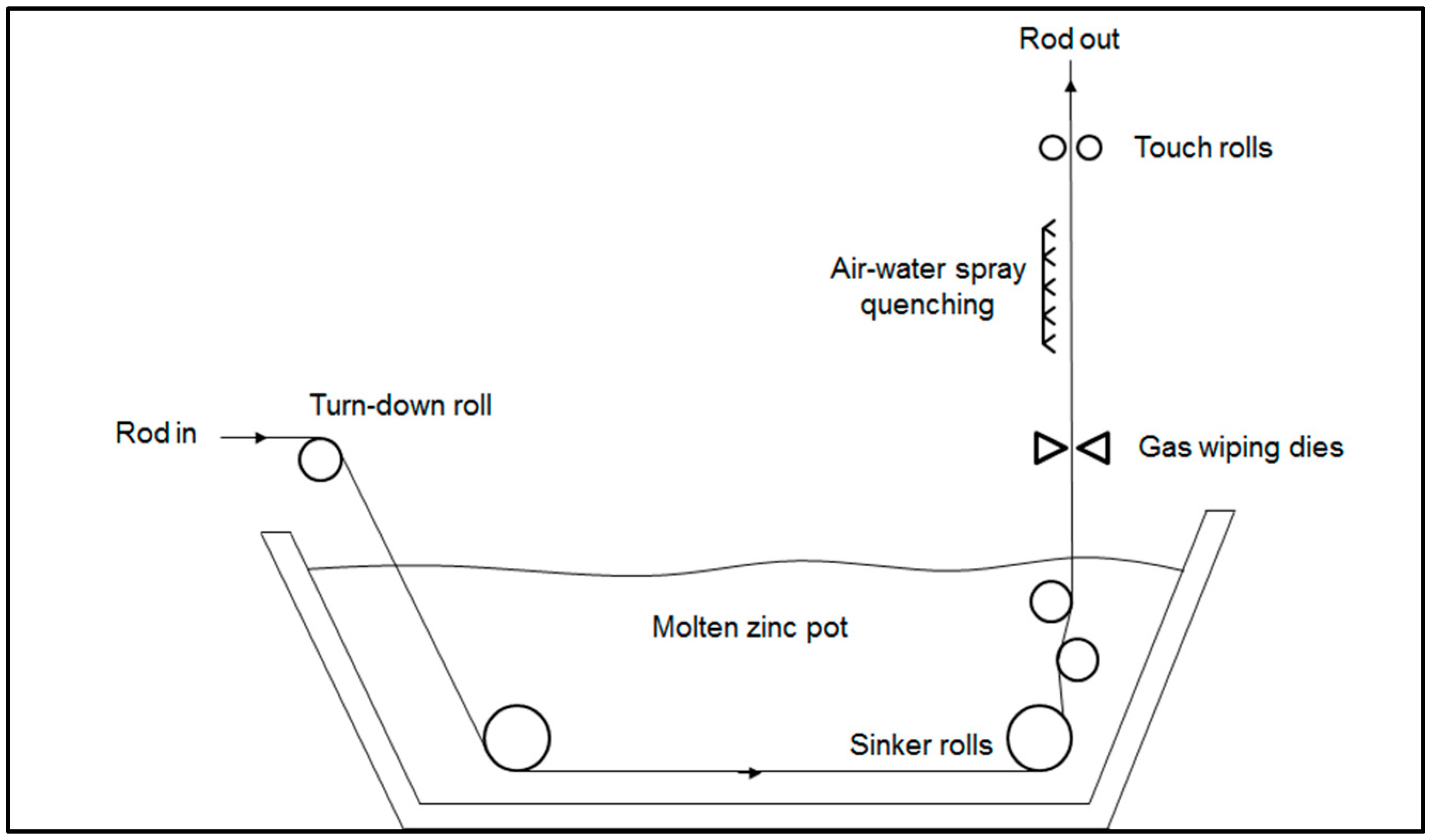
1]. The lead particles remaining attached to the rod surface are removed by acid pickling, which is also a necessary surface pre-treatment for the following hot-dip galvanizing step. Before the immersion in the molten zinc bath, the steel rod is fluxed in an aqueous solution containing chloride salts to avoid any surface oxidation. The steel rod is then maintained in contact with the molten zinc at around 440–460 °C for a few minutes to form the galvanized coating on its surface [
2]. At the exit from the molten zinc bath, the inert gas wiping dies accurately control the thickness of coating on the surface by removing the excess of molten zinc. Then the steel rod is spray quenched with a mixture of air and water to obtain a bright shiny finish [
3] (
Figure 1).
The zinc coating increases the corrosion resistance of the steel substrate [
4] and it is a good solid lubricant to minimize the friction during the cold drawing process [
5]. This process involves pulling the rod through a series of dies, with the diameter progressively reducing in size. At the exit of the last die, a small diameter wire (<5 mm) is produced with enhanced tensile strength properties due to the intense work hardening.
The as-fabricated galvanized steel wire needs to pass a number of quality tests before going on the market, concerning mechanical and corrosion properties. One of these is the torsion test that consists of counting the number of turns that the wire can sustain before failure.
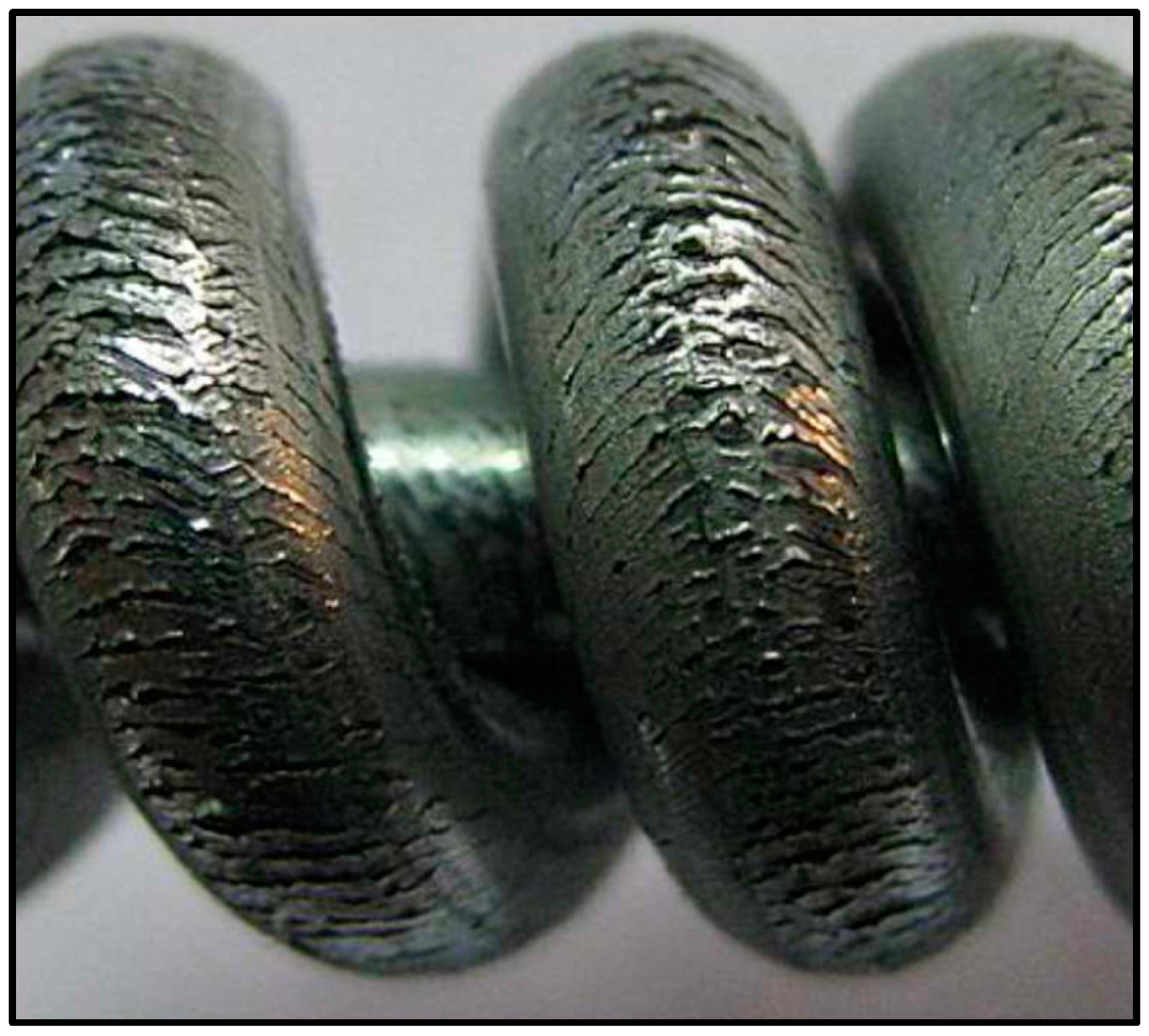
In the present case, as reported by plant operators, the wire produced with specific steel batches at the end of the torsion test showed the formation of several circumferential cracks, randomly distributed along the circumference and length (
Figure 2). A preliminary analysis showed that these cracks are limited to the Zn layers, suggesting that the coating could have some problems of adhesion or excessive brittleness.
In literature, the studies concerning the defects in galvanized coatings are mainly related to problems of delamination, also named “peeling off” or “shaving” of zinc coating, which happens during the forming operations. The main reasons that can produce this type of defect are the excessive plastic deformations [
6], the abnormal growth of a brittle zeta phase in the coating [
7,
8], the presence of Mn oxide formed on the surface of the steel substrate during annealing before galvanizing [
9,
10].
To investigate the present problem, systematic metallographic investigations were performed on steel rods and wires by optical (OM) and scanning electron microscope (SEM). Micro bidimensional X-ray diffraction experiments (μXRD
2) were also carried out to measure the residual stress in the coatings. A failure mechanism has been proposed also on the base of Finite Elements Methods (FEM) simulations that are normally used to model thermo-mechanical processes [
11,
12] and verified with in-plant tests.
Proper countermeasures have been adopted in the plant to solve the problem.
3. Results and Discussion
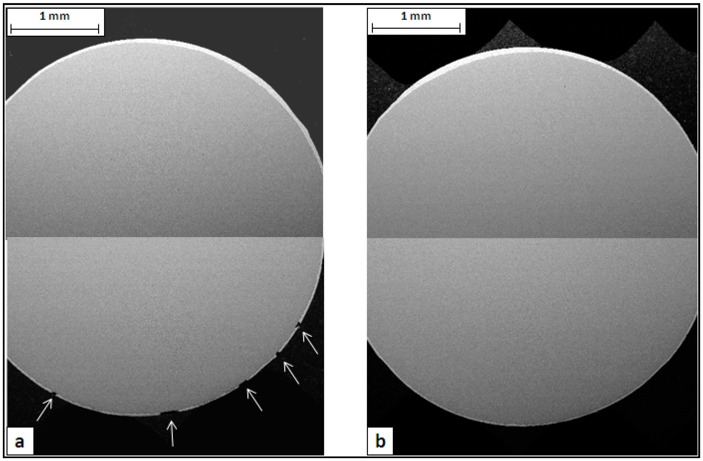
The metallographic analysis started considering the transversal sections of wires made with Steel 1 and 2 (
Figure 4). The images, collected by SEM in backscattering mode at low magnification, show the zinc-rich coating as a thin white layer on the grey steel substrate. In both cases, it is evident that the thickness of the zinc layer is not uniform along the circumference. This is probably due to an excess of molten zinc that remained attached on the rod surface at the exit from the galvanizing bath. The analysis of rod cross sections showed the same uneven coating thickness, confirming this hypothesis. It is interesting to observe that in the failed wire, the defects are located only in one part of the cross section, where the coating is thinner (
Figure 4a).
The metallographic analysis was then focused on the failed batch. Longitudinal sections were cut from both the Steel 1 wire and rod and etched by Nital2 to reveal the coating microstructure. SEM images were collected in back-scattering mode and reported in
Figure 5 and
Figure 6. Three layers can be clearly detected based on their iron content, measured by means of the EDS microprobe: eta (almost pure zinc), zeta (5%–6% wt. Fe) and delta (7%–11.5% wt. Fe) phase [
2]. The gamma phase is also present as a very thin layer at the interface with the substrate. In any case, the lateral resolution of the EDS microprobe is not high enough to identify this phase separately from the others.
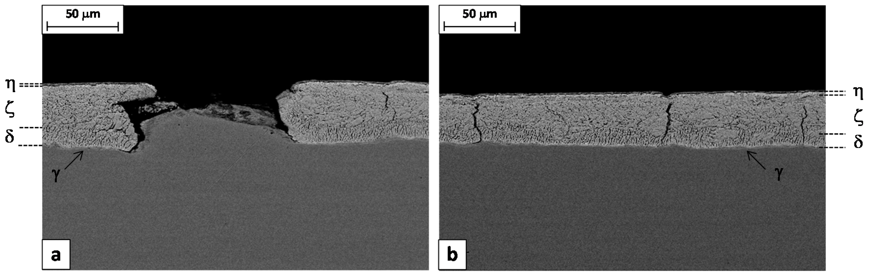
Figure 5a shows the longitudinal cross section of a defect responsible for the macroscopic failure of the wire during the torsion test. It consists of the local delamination of the Zn coating, which is missing for a length of about 100 μm. The steel substrate in the delaminated area is not flat but it shows a microscopic bulging.
The residual zinc coating appears severely deformed by drawing, with the formation of several thin short cracks perpendicular to the substrate. Such cracks are confined to the delta layer, which is reasonable considering that this phase is more brittle than the others [
20].
Long vertical cracks are also frequently present in the rest of the coating, at intervals of about 100–150 μm (
Figure 5b). These cracks start from the interface with the substrate or from the gamma/delta interface and propagate along both the delta and the zeta layers, stopping when in contact with the eta phase that is soft and ductile.
It is interesting to observe that the length of the detached fragment is similar to the distance between two consecutive long cracks. Furthermore, in
Figure 5a, one can observe that the left edge of the micro-bulged substrate fits almost perfectly into the cracked coating. These two observations suggest a possible mechanism for the formation of this kind of defect. It consists of two steps: (1) pulling the rod through the first drawing dies, a small fragment of the coating in between two long cracks is detached, (2) passing in the remaining dies, the steel substrate is coined in the “free space” remaining between the substrate and the die, giving the final appearance to the defect.
Figure 6a shows that the long vertical cracks are already present in the coating before the rod is drawn. In the region where the coating is thinner and the eta layer is almost absent, the cracks are able to pass the zinc coating completely. On the contrary, where the coating is thicker, the extra thickness consisting of the ductile eta layer avoids the propagation of the crack to the outer surface (
Figure 6b).
This is in agreement with the previous observation that the defects are normally absent where the coating is thicker. The beneficial role of the ductile eta layer would be to mitigate the coating failure, sustaining cracked fragments of the brittle zeta, delta and gamma layers during the forming process.
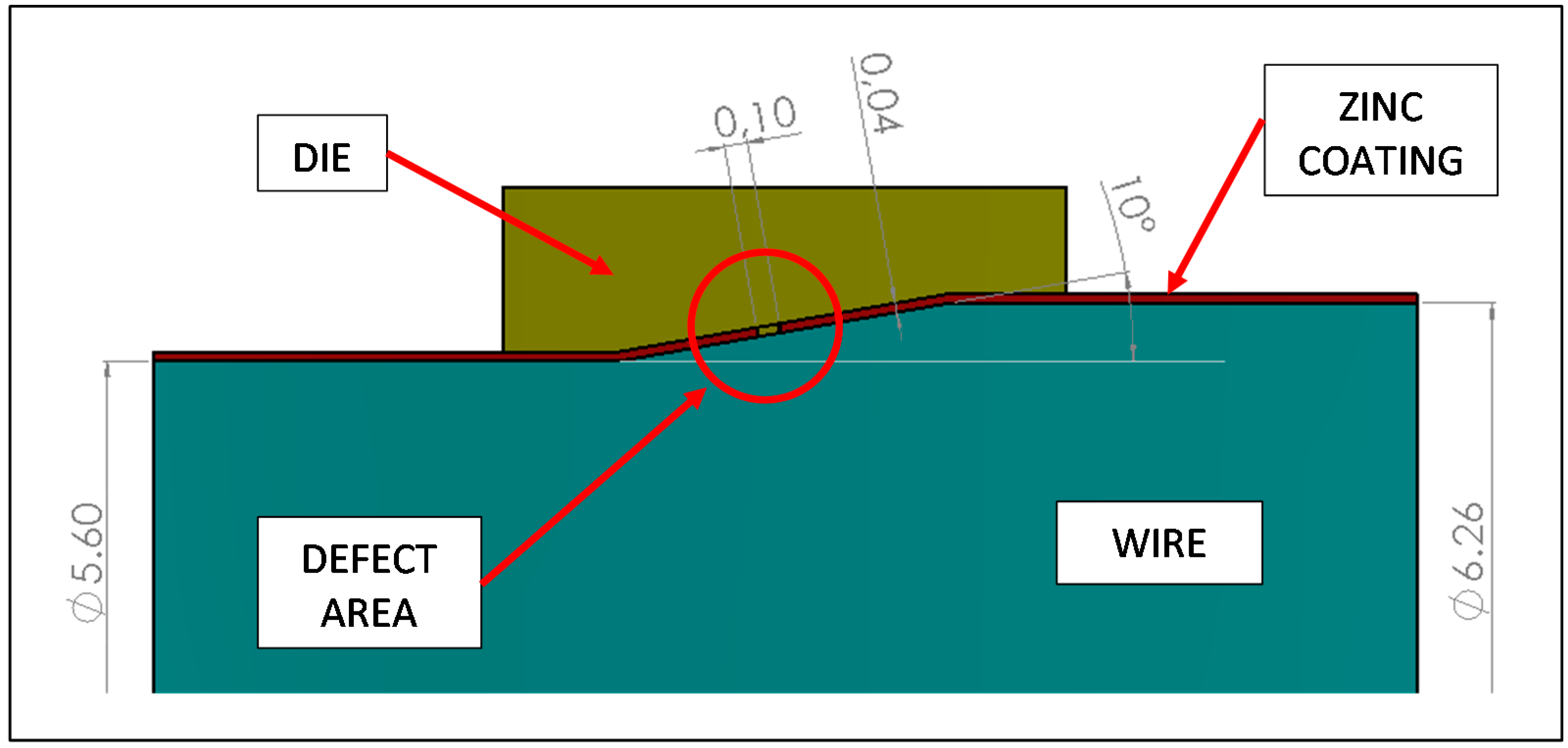
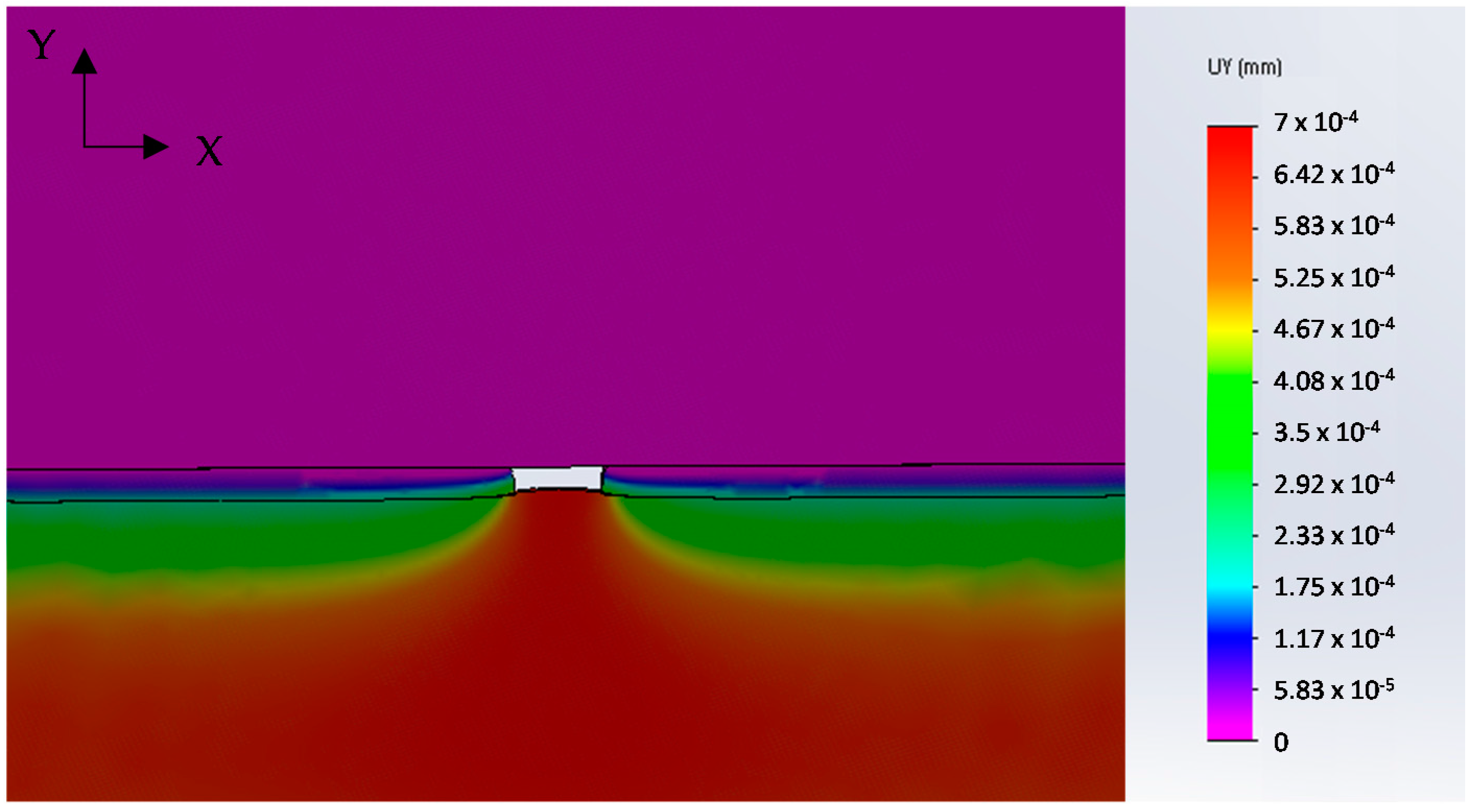
Numerical analysis was applied to simulate the drawing of a galvanized steel wire containing the full detachment of the coating for a length of 40 μm. The results are presented in
Figure 7 that shows the Y-displacements distribution in the area close to the defect. The tendency of steel substrate to protrude into the “free space” left by the coating is evident, in agreement with the morphology observed in
Figure 5a.
This result supports the hypothesis that the origin of failure is the detachment of a coating fragment during the first drawing steps, favored by the presence of through-thickness cracks (
Figure 6b).
The presence of the vertical cracks in the hot dipped Zn coating is not surprising. The coefficient of thermal expansion of the coating layer is higher than that of the substrate steel, accordingly, the coating layer can suffer from multiple cracking during cooling, due to the thermally induced tensile stresses [
18,
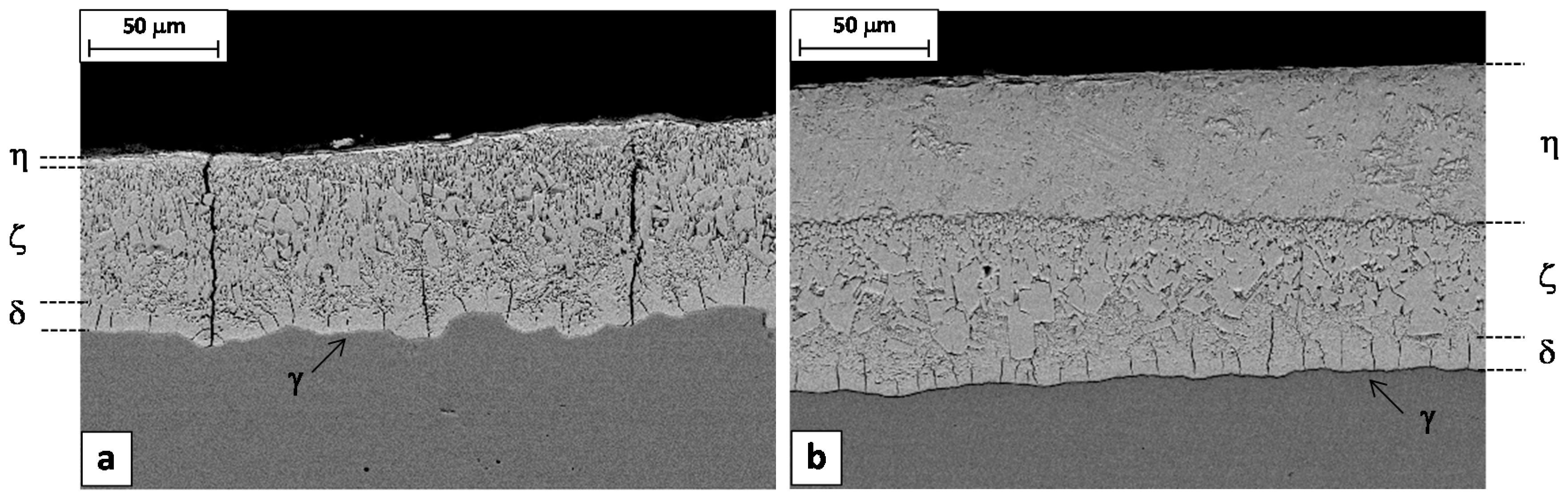
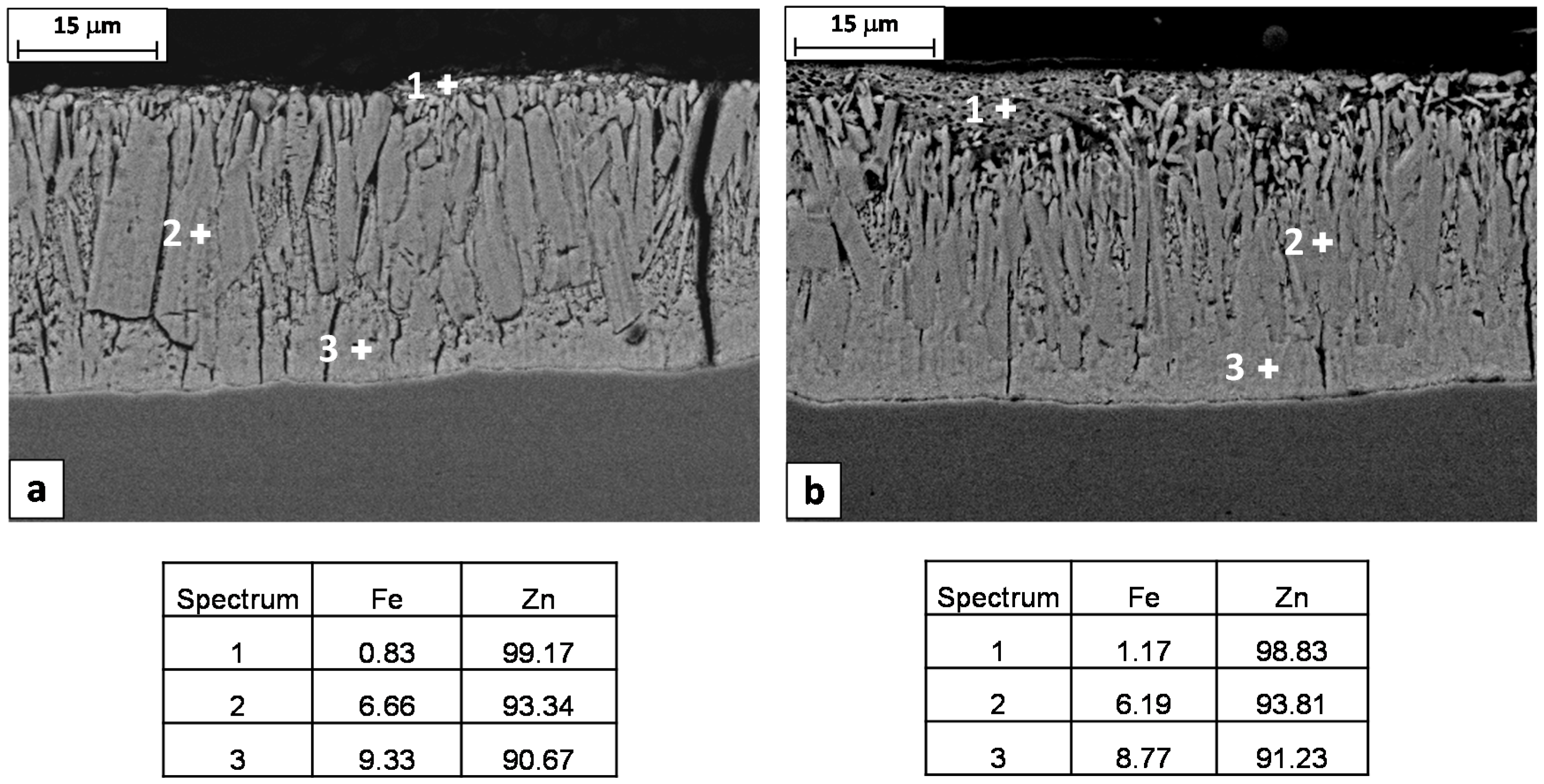
21]. In any case, comparing the galvanizing coatings on the steel rods 1 and 2, it is evident that the through-thickness cracks are present only in the case of steel 1 (
Figure 8). This can be explained considering that the two coatings have a different microstructure. In the case of steel 1, the columnar grains of the brittle zeta layer are coarser and the thickness of the soft eta layer is smaller compared to the steel 2 (
Figure 8a). These conditions decrease the toughness of the coating, facilitating the propagation of cracks under the action of thermally induced tensile stresses.
The galvanized coating microstructure is strictly related to the chemical composition of steel. It is well known that in the process of hot-dip galvanizing, even small amounts of silicon in the substrate can increase the reactivity of the molten zinc. In steels with a content of Si of about 0.1 wt. %, the obtained coating exhibits the excessive growth of the intermetallic layers, resulting in poor mechanical and adhesion properties. This phenomenon is known as the Sandelin effect [
22,
23]. Also, P has synergetic activating effects on the reactivity of Si with molten zinc. Their conjoint effect is known as equivalent silicon (Si
eq) and is defined as: Si
eq = %Si + 2.5%P. The recommended equivalent silicon for galvanizing steels is in the range of 0.14%–0.20% or less than 0.09% [
6]. Beyond these limits, the coating has the tendency to be thicker, more porous and brittle.
The Steel 1 and 2 considered in this study have a Sieq of 0.25% and 0.21% respectively. These values are both above what it is considered the optimal range for the galvanizing process. In particular, the higher value of Sieq of Steel 1 can justify the different coating microstructure and its higher tendency for cracking.
The EDS chemical analysis of the coating layers also confirms that the Steel 1 has a higher reactivity with the molten zinc respect to Steel 2, showing higher contents of Fe in both zeta and delta phases (
Figure 8).
Starting from these considerations, the high carbon steels processed in the plant were monitored to put in relation their chemical compositions with the frequency of cracks in galvanized wires. The results, reported in
Table 3, show that a direct link exists between the failures and the silicon equivalent index. The wire made with a steel having the Si
eq index above 0.21% displays a high percentage of coating failures, while steels with a lower Si
eq index had no problems.
All these results confirmed that the formation of the multiple through-thickness cracks, responsible for the failure of the galvanized coating during the torsion test, depends on two main factors:
the intrinsic brittleness of the coating, when steel has the Sieq index above 0.21%,
the high thermal tensile stresses developed during the cooling after galvanizing.
Avoiding this problem by controlling the Si
eq index always below the limit of 0.21% is probably not a viable solution, as silicon is an alloying element essential to improve the mechanical strength and the homogeneity of high carbon steels [
24] or to promote the deoxidation of the melt during the steelmaking processes [
25].
A better strategy could be trying to decrease the thermal stresses developed in the coating by reducing the cooling rate at the exit from the galvanizing bath. To test this approach, the rods made with the steel from the Batch 9 (see
Table 3) were galvanized in two different ways:
- -
Steel 9A: by using the standard process;
- -
Steel 9B: by switching off the air–water spray at the exit from the Zn bath, in order to decrease the cooling rate.
The longitudinal residual stresses were measured on these samples by means of μXRD
2 technique.
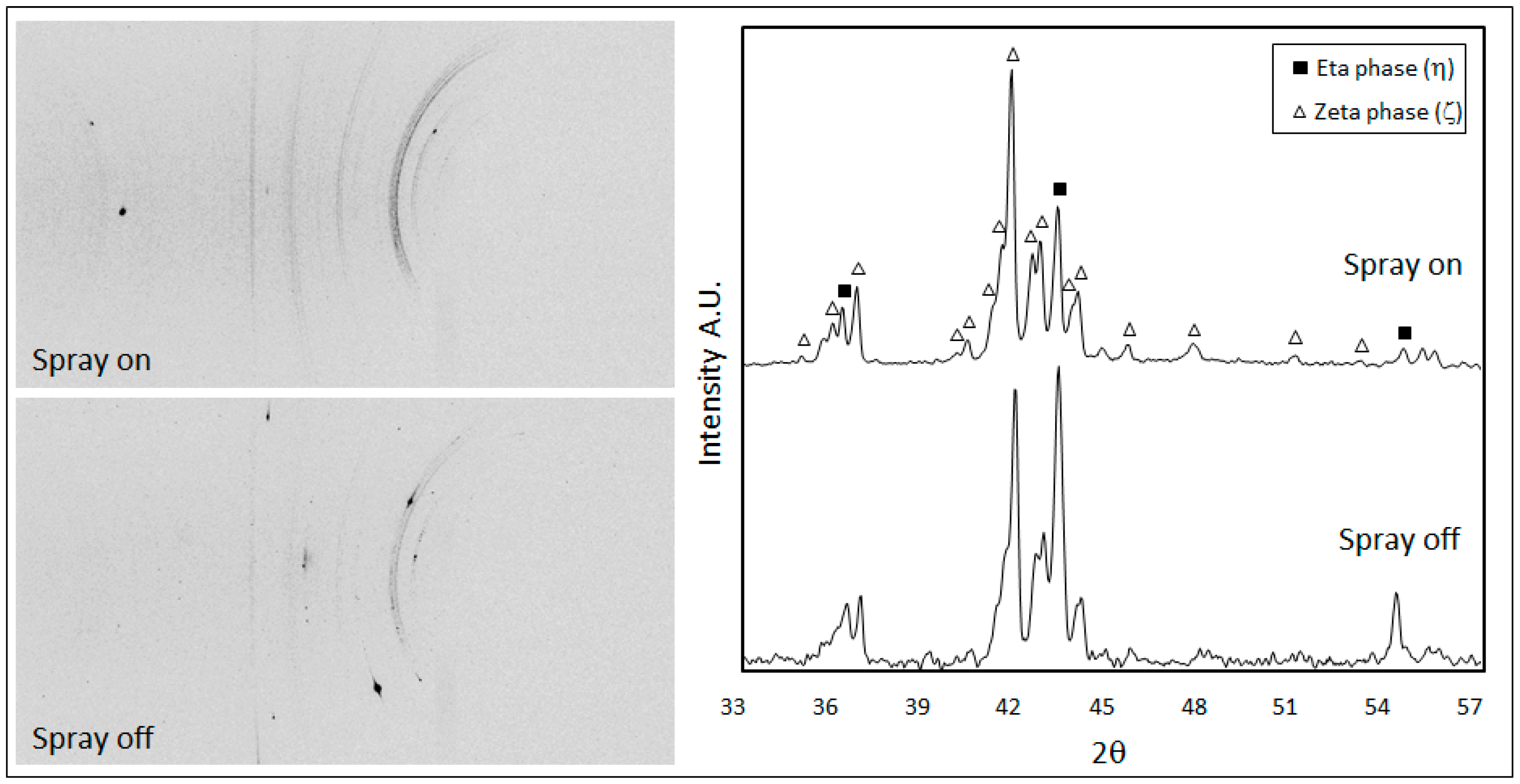
Figure 9 shows the 2D diffraction images collected from the samples 9A and 9B and the relative integrated diffractographs. According to the limited penetration depth of X-rays and the small incidence angle used in the experiments, only the diffraction peaks of the outer layers were detectable: the hexagonal eta phase (PDF#04-0831) and the monoclinic zeta phase FeZn
13 (PDF#65-1238). In both samples, the Debye rings are not continuous but spotty, which means that the crystalline domains are rather large. This is true especially in the case of steel sample 9B, where the air–water spray was switched off giving more time to crystallites to solidify and grow.
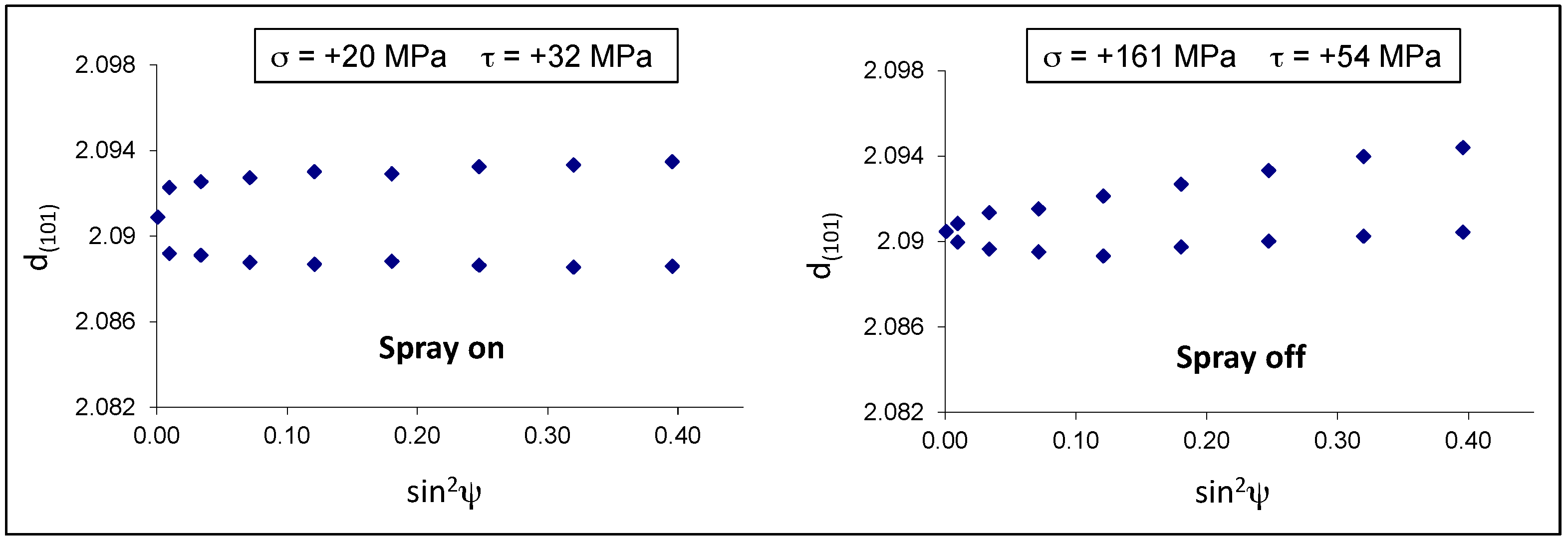
The residual stresses were calculated for the eta phase by measuring the deformation of the (101) Debye ring. Positive and negative ψ angles were considered. The d-sin
2ψ graphs in both samples show an elliptical curvature, named ψ-splitting [
26], due to shear stresses near the sample surface, probably related to interfacial stresses between the eta and zeta layers (
Figure 10). It is interesting to observe that the air-cooled sample 9B developed normal tensile stresses (+161 MPa) much higher than those present in the spray-quenched one (+20 MPa).
From a theoretical point of view, if the difference in thermal shrinkage between zinc and steel is fully accommodated by the elastic deformation of crystal lattice, then the misfit stress in the zinc coating will be more than 700 MPa at room temperature. However, works in literature showed that the actual residual stresses measured by XRD in the hot-dip zinc coatings are much lower, in the order of 100–200 MPa [
9]. This is because the major part of the thermal misfit has been accommodated by plastic deformation of the zinc grains and/or by formation of microcracks along the zinc grain boundaries.
In the present case, the spray quenched sample shows residual stresses close to zero, probably because many microcracks developed in the eta layer and relaxed the tensile stresses almost completely. On the contrary, in the sample 9B, the slower cooling rate gave more time to accommodate the misfit between the coating and the steel by means of elastic and plastic deformation.
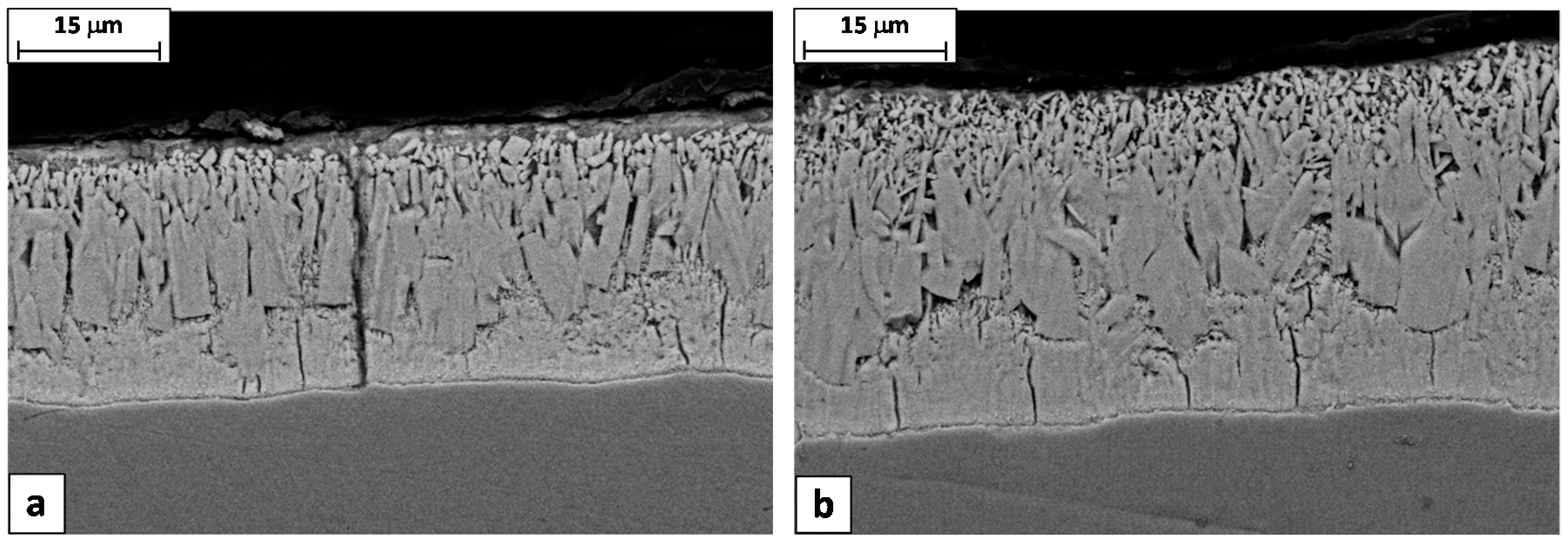
Longitudinal cross sections cut from the samples 9A and 9B confirmed this interpretation, showing that the through-thickness cracks are frequently encountered in the spray-quenched sample, while in the other one the cracks are always confined just in the delta layer (
Figure 11). So, as expected, the soft cooling reduced the coating tendency to cracking. It is worth noting that the wire produced with the steel 9A had a high percentage of failures during the torsion test, while no failures were observed in the case of wire produced with the steel 9B.
In conclusion, the proper countermeasure to prevent this type of failure was to reduce or completely switch off the air–water sprays when the Sieq index of the rods’ steel exceeds the critical value of 0.21%.
4. Conclusions
This study showed that the cracks of galvanized high carbon steel wires developed during the torsion test are a consequence of preexisting through-thickness cracks in the rods’ coating. During the drawing process, from these weakened points, small fragments of the coating are detached, creating the final defects.
The presence of multiple through-thickness cracks in the rods’ coating depends mainly on two factors: the high thermal tensile stresses developed during the cooling down at the exit from the galvanizing bath and the intrinsic brittleness of the coating when the steel substrate has a Sieq index above 0.21%. In this case, a coarser and more brittle microstructure is formed and, in particular, the thickness of the soft eta layer is almost zero, losing its ability to sustain the cracked fragments of intermetallics during the forming process.
In order to reduce the thermal stresses developed in the coating and the consequent cracks, in-plant tests were performed on steel rods with the Sieq index above 0.21%, by switching off the air–water spray at the exit from the zinc bath. Measurements by micro X-ray diffraction showed that the reduction of cooling rate changed the residual stress state in the coating and the metallographic analysis confirmed the absence of through-thickness cracks. This solution completely solved the problem of coating failure in the wire.
In conclusion, it was proved that an effective countermeasure to prevent this failure consists of controlling the intensity of the air–water sprays accordingly to the Sieq index of the steel rods.


