Grain Refinement and Mechanical Properties of Cu–Cr–Zr Alloys with Different Nano-Sized TiCp Addition

Key Laboratory of Automobile Materials of Ministry of Education, Department of Materials Science and Engineering, Jilin University, Changchun 130025, China
*
Authors to whom correspondence should be addressed.
Materials 2017, 10(8), 919; https://doi.org/10.3390/ma10080919
Submission received: 11 July 2017
/
Revised: 4 August 2017
/
Accepted: 5 August 2017
/
Published: 8 August 2017
Abstract
:The TiCp/Cu master alloy was prepared via thermal explosion reaction. Afterwards, the nano-sized TiCp/Cu master alloy was dispersed by electromagnetic stirring casting into the melting Cu–Cr–Zr alloys to fabricate the nano-sized TiCp-reinforced Cu–Cr–Zr composites. Results show that nano-sized TiCp can effectively refine the grain size of Cu–Cr–Zr alloys. The morphologies of grain in Cu–Cr–Zr composites changed from dendritic grain to equiaxed crystal because of the addition and dispersion of nano-sized TiCp. The grain size decreased from 82 to 28 μm with the nano-sized TiCp content. Compared with Cu–Cr–Zr alloys, the ultimate compressive strength (σUCS) and yield strength (σ0.2) of 4 wt% TiCp-reinforced Cu–Cr–Zr composites increased by 6.7% and 9.4%, respectively. The wear resistance of the nano-sized TiCp-reinforced Cu–Cr–Zr composites increased with the increasing nano-sized TiCp content. The wear loss of the nano-sized TiCp-reinforced Cu–Cr–Zr composites decreased with the increasing TiCp content under abrasive particles. The eletrical conductivity of Cu–Cr–Zr alloys, 2% and 4% nano-sized TiCp-reinforced Cu–Cr–Zr composites are 64.71% IACS, 56.77% IACS and 52.93% IACS, respectively.
1. Introduction
Cu-matrix composites and Cu alloys were widely used as functional and structural materials [1,2,3,4,5,6], such as electrodes for electrical-resistance welding, electric switches, lead frames, friction pieces, as well as a cooling medium of the magnetic channel, encapsulating material on account of their good wear resistance [7], excellent electrical and thermal conductivities [8,9], and good corrosion resistance [10,11] etc. Recent research indicates that the dispersion of ceramic particles in the copper matrix could play a role in pinning dislocation movement and improving the strength of the composites, in addition, alloying elements can also enhance Cu alloy [12,13,14,15]. For example, Lu et al. [15] fabricated 40–60 vol % TiCx–TiB2/Cu composites by thermal explosion reaction synthesis. They found that the ultimate compressive strength increased with the ceramic content and the microhardness of the 40–60 vol % TiCx–TiB2/Cu composites reached 339, 404 and 448 HV, respectively. However, the electrical and thermal conductivity of Cu was reduced because of the high content of ceramic particles. Zhang et al. [2] revealed that the microhardness of solid soluted Cu–Cr–Zr alloys was 181.8 HV, which was much higher than that of pure copper (68 HV), with less decreasing electrical conductivity (70.8% IACS). Nevertheless, the microhardness is much less than those of particle-reinforced Cu matrix composites. Qiu et al. [12] fabricated the 50 vol % TiC–TiB2/Cu composites with different Cr content. Abrasive wear results showed that the volume loss of the 50 vol % TiC-TiB2/Cu composites decreased with Cr content and the composites had an extremely low wear rate compared with pure Cu. Afterwards, Qiu et al. [13] studied the influence of the addition of Zr with different content on the compressive properties of TiC-TiB2/Cu composites; the ultimate compressive strength (σUCS), yield strength (σ0.2) and hardness increased with Zr content. Results demonstrated that Cu could be enhanced both by ceramic particles and Cr, Zr elements.
Among the numerous reinforcing particles, titanium carbide (TiCx) is an attractive reinforcing phase [16,17,18,19,20] due to its high modulus (470 KN/mm2), hardness (2800 HV) and melting point (3067 °C). Combustion synthesis is one of the in-situ methods to fabricate metal matrix composites reinforced with TiCp [21,22,23,24,25,26,27,28,29,30]. There are many advantages of this method. For example, its simple preparation process can result in a low cost, and the clean particle-matrix interface leads to strong interfacial bond, and its synthetic mechanism brings about the uniform distribution of particles. Moreover, combustion synthesis can synthesize TiCp with various sizes, morphologies and contents in different metal matrix [21,22,23,24,25,26,27,28,29,30,31,32,33,34,35,36,37]. A number of researches showed that the decreasing size of reinforcing particles (<100 nm) had an improvement than that of micro ones in the composites [38,39,40,41]. Therefore, nano-sized TiC particles as reinforcement have attracted many researchers’ attention.
Nano-sized TiC particles could be prepared by altering the matrix content in a Cu–Ti–C system. According to our previous study [34], nano-sized TiCx could be fabricated when the Cu content was below 30 vol % in a Cu–Ti–CNTs system. However, Cu content determined the possibility of whether combustion synthesis could be self-sustaining or not. Liang et al. [42] studied the effect of adiabatic temperature (Tad) as well as Cu content on the TiCP fabricated by combustion synthesis (CS) in the Cu–Ti–C system. They found that Cu content should not exceed 67.12 wt % with corresponding Tad no less than 1800 k for the self-sustaining reaction. As for combustion synthesis reaction in a continuous heating furnace in Cu–Ti–C system, Cu content should be no less than 94.2 wt %. As a result, it can be comfirmed that TiCx/Cu composites with low content TiCx were not able to be synthesised via CS. However, high TiCx content will greatly reduce the electrical conductivity. Accordingly, a new method used to fabricate low content TiCp-reinforced Cu–Cr–Zr composites is needed. Casting is a cost-effective and efficient method of fabricating large and shaped parts [35,43]. Ex situ is the main way of fabricating particle reinforced metal matrix composites (PRMMCs) for casting method. The microstructures of the casting alloys were able to be controlled by casting and hot treatment process [3,4]. However, compared with casting method, particle shape can be controlled and size is uniform for in situ particles. Meanwhile, unlike combustion synthesis method, casting method can realize small amount of particle addition. Accordingly, the preferred method of fabricating TiCp-reinforced Cu–Cr–Zr composites should be casting combined with combustion synthesis to exert the advantages of the two methods. As is well known, most ceramic particle and Cu belong to nonwetting system, therefore, particles reinforced Cu matrix composite confront the problem of interface bonding strength. This new method of fabricating particles reinforced Cu matrix composite by combining combustion synthesis with electromagnetic stirring casting will solve the following problems: (a) this method can solve the nonwetting problem, interfacial reaction resulting in the improvement of bonding strength. (b) compared with ex situ method, the clean interface between the reinforcing phase and the matrix, leading to a strong interfacial bonding. (c) unlike the in situ method, this method is not limited by the content, it can fabricate any content as you like. Accordingly, this method will provide a new way of fabricating ceramic particle reinforced Cu matrix composite.
Pushkar Jha et al. [44] studied TiC-reinforced Cu-4 Cu-Ti-C Ni matrix composites with different particle contents fabricated by powder metallurgy. Hardness and friction as well as wear results of composites show better wear resistance than unreinforced matrix alloy. Qiu et al. [12] prepared 50 vol % (TiC–TiB2)/Cu composites with different Cr additions via combustion synthesis combined with hot press, abrasive wear results revealed that the abrasive wear of the (TiC–TiB2)/Cu composites consists of two stages. First, the Al2O3 abrasive particles penetrate into the soft copper matrix and cut it. In the second stage, the TiC and TiB2 ceramic particles are exposed from the copper matrix and they act as a barrier to the micro-cutting action of the abrasives. The abrasive wear resistance of the 50 vol % (TiC–TiB2)/Cu composites with 7 wt % Cr addition was improved by 138% compared with pure Cu. It is clear from the above that the enhancing principles of PRMMCs are the exposed ceramic playing as barriers, which enhanced the wear resistance of the composites.
In this research, nano-sized TiCp-reinforced Cu–Cr–Zr composites were prepared by the dilution of TiCp/Cu master alloy into Cu–Cr–Zr alloys; the TiCp/Cu master alloy was fabricated by thermal explosion reaction in Cu–Ti–CNTs system. The electrical conductivity and compressive properties of the TiCp reinforced Cu–Cr–Zr composites were studied. Furthermore, the wear behavior and law of the TiCp-reinforced Cu–Cr–Zr composite was studied. This will provide some guidance for the fabrication of TiCp-reinforced Cu–Cr–Zr composites and its application.
2. Materials and Methods
Cu powder with a particle size of ~45 μm, CNTs ~15–80 μm in length and ~10–20 nm in diameter and Ti powder ~25 μm in size were used to fabricate TiCp/Cu master alloys via combustion synthesis. Cu, Ti and CNTs powders were weighed accurately, which was calculated according to the C/Ti mole ratio of 0.8:1. The reactants’ compositions was 70% Cu in volume. The prepared powders were milled on a planetary mixer with six cylindrical ceramic inwall containers at the speed of 50 rpm for 24 h. The blended powder was compressed into cylindrical compacts under the pressure of 100 MPa. The size of the compacts was 29 mm in diameter and 45 mm in height. Afterwards, the compacts were placed into a high strength graphite mold, which was later put into a self-made vacuum furnace and heated. W5-Re26 thermocouples were used to measure the temperature. When the temperature rose rapidly, stopped heating and pressed with the pressure of 40 MPa. The nano-sized TiCp/Cu master alloy was obtained when it was cooled down to room temperature.
The Cu–Cr–Zr composites reinforced with different TiCp content were prepared by the dilution of TiCp/Cu master alloy into Cu–Cr–Zr alloys via stirring casting. At first, the prepared Cu–Cr–Zr alloys were heated in a high purity graphite crucible, which was later placed in an induction furnace with a water cooling system. Once the Cu–Cr–Zr alloys melted, the TiCp/Cu master alloy was added in the molten Cu–Cr–Zr. Manual stirring was helpful to melt and disperse the master alloy. Once the master alloy melted completely, kept the temperature for 3 min and the melt were poured into a steel mold. After cooling down to indoor temperature, the TiCp-reinforced Cu–Cr–Zr composites with different TiCp content were successfully prepared.
The characterization of phase constitutions of TiCp/Cu master alloy were performed on a X-ray diffraction (XRD, Rigaku D/Max 2500PC, Tokyo, Japan) with Cu Kα radiation at the scanning speed of 4°/min. The TiCp in TiCp/Cu master alloy were extracted by FeCl3-HCl distilled water solution, the morphologies of TiCp were detected by Field Emission Scanning Electron Microscope (FESEM, JSM 6700, Tokyo, Japan). Olympus optical microscope (XJZ-6, Tokyo, Japan) and high resolution transmission electron microscopy (HRTEM, JEM-2100F, Tokyo, Japan) were used to observe the microstructure of the Cu–Cr–Zr alloys and TiCp-reinforced Cu–Cr–Zr composites. The compressive properties were proceeded on a servo hydraulic materials testing system (MTS, MTS 810, Minneapolis, MN, USA) at a strain rate of 3 × 10⁻⁴ s−1. Microhardness of the Cu–Cr–Zr alloys and TiCp-reinforced Cu–Cr–Zr composites were performed by a Vickers hardness tester (Model 1600-5122VD, Newage, Feasterville, PA, USA) using a static load of 50 gf and a dwell time of 15 s. Abrasive wear tests were carried out on a pin-on-disk machine with the SiC abrasive papers, the load was 5 N and the wear distance was 24.78 m. The abrasive wear samples are 12 mm in height and 6 mm in diameter. The electrical conductivities of the Cu–Cr–Zr alloys and TiCp-reinforced Cu–Cr–Zr composites were measured at room temperature by a digital eddy current electroconductive machine (Sigma 2008b, Xiamen, China), International Annealed Copper Standard (IACS) are quoted as the units of electrical conductivity results.
3. Results and Discussion
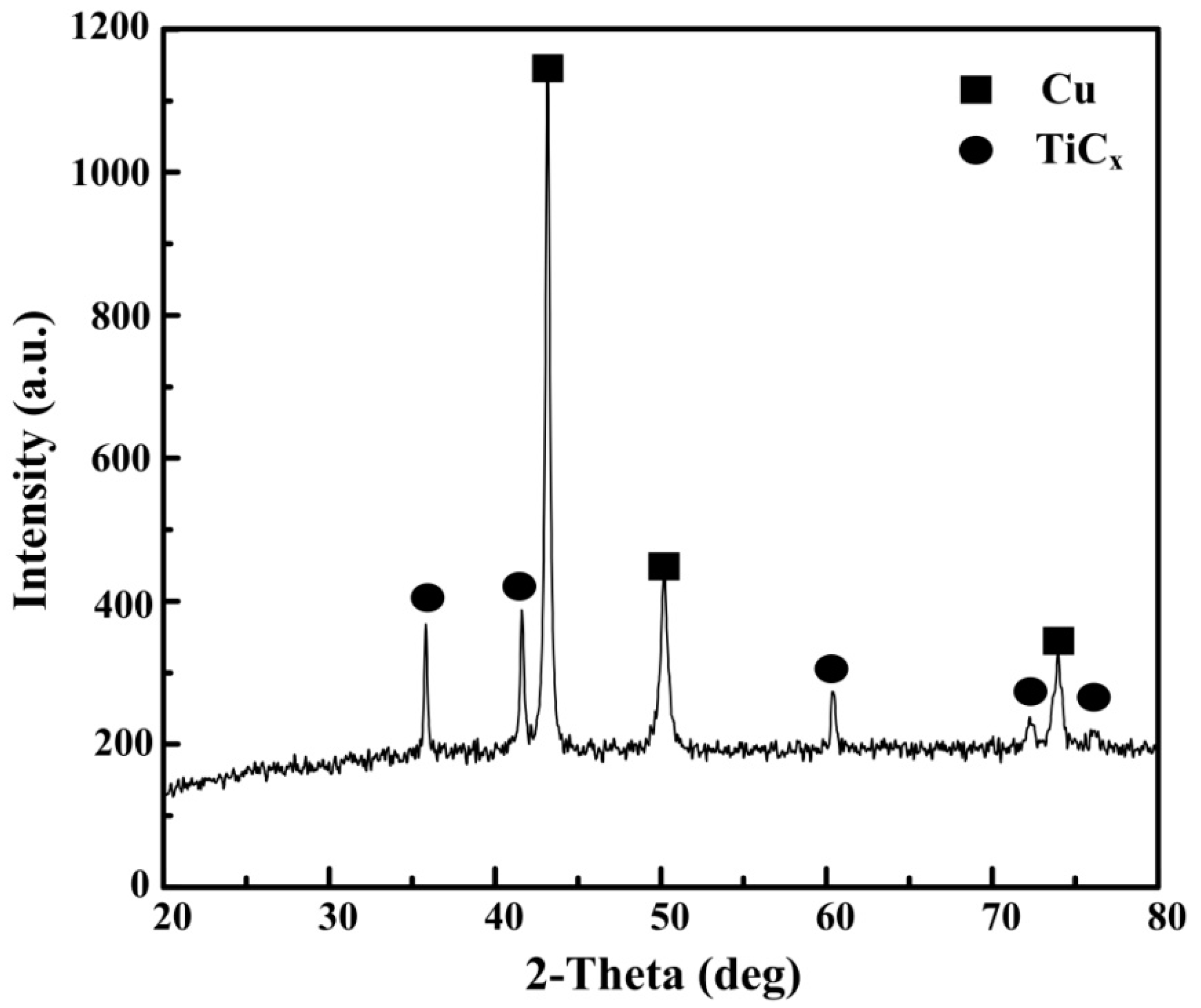
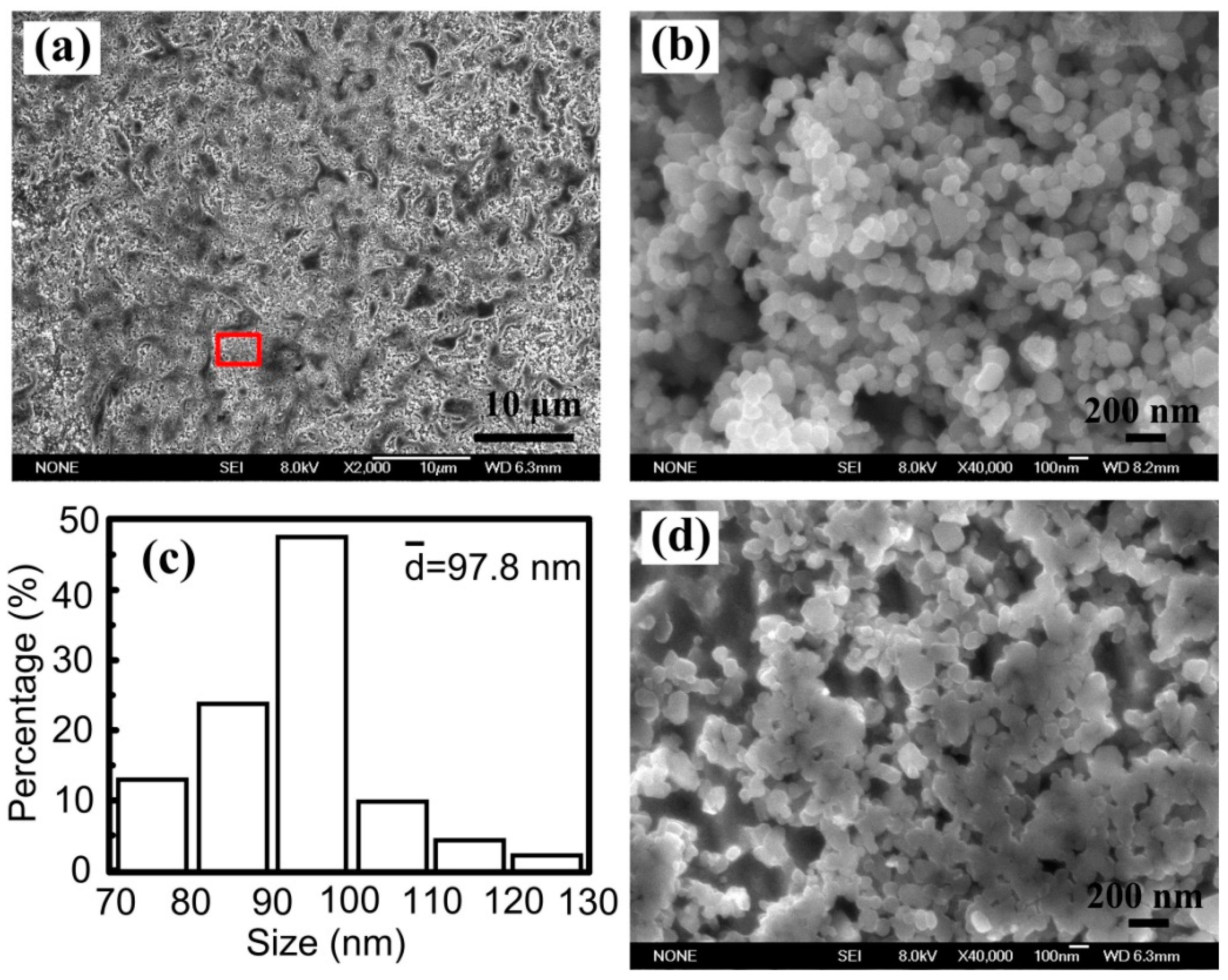
Figure 1 shows the XRD results of Cu–Ti–CNTs master alloy fabricated by combustion synthesis. The diffraction peaks belonging to TiCp and Cu can be seen clearly, indicating that the in-situ nano-sized TiCp/Cu master alloy was successfully fabricated. Figure 2a shows the morphology of the deep etched surfaces of the nano-sized TiCp/Cu master alloy. As can be seen, Cu was removed and the TiCp in the TiCp/Cu master alloy exhibited a homogeneous distribution. The morphologies of extracted nano-sized TiCp were shown in Figure 2b. As indicated, the morphologies of the extracted TiCp in TiCp/Cu master alloy are spherical, with the size of 100 nm on average (Figure 2c). The interspace between TiCp of the magnified image of the selected area can be observed (Figure 2d).
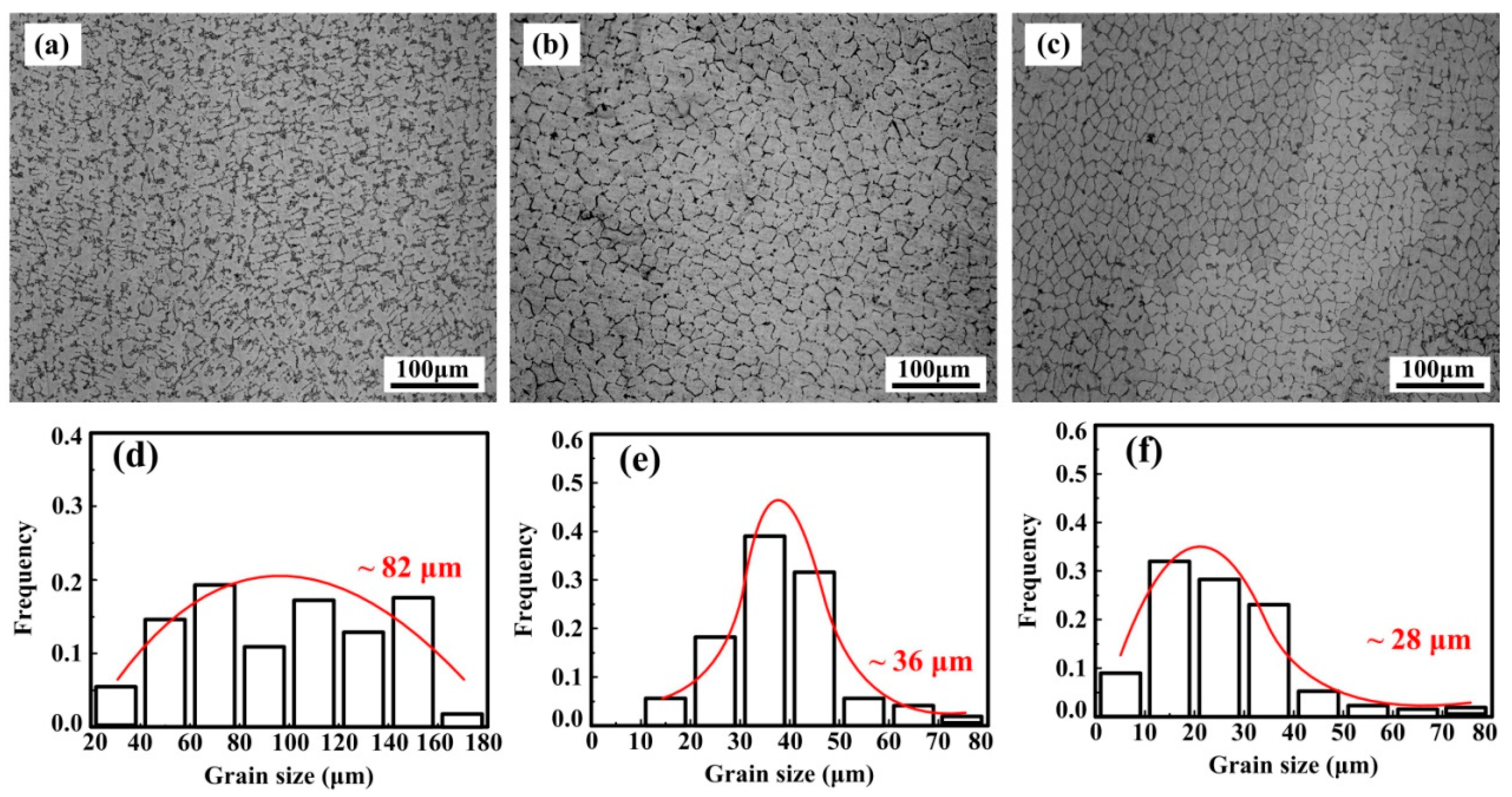
The microstructures of nano-sized TiCp/Cu–Cr–Zr composites with different TiCp content are shown in Figure 3. As illustrated, dendritic grain is the main morphology of Cu–Cr–Zr alloys with the grain size of 82 μm on average; the morphologies of the grain in 2 wt % and 4 wt % nano-sized TiCp-reinforced Cu–Cr–Zr composites are equiaxed crystal and the grain size are 36 μm and 28 μm on average, respectively. The morphology of the grain changes from coarse dendrites to equiaxed crystal with increasing TiCp content. An investigation [45] suggested that TiCp were not the effective substrates for the heterogeneous nucleation of the Cu-melt. However, the variation in grain from dendrites to equiaxed crystal was a piece of adverse evidence for the ineffectiveness of TiCp in grain refinement in Cu alloy.
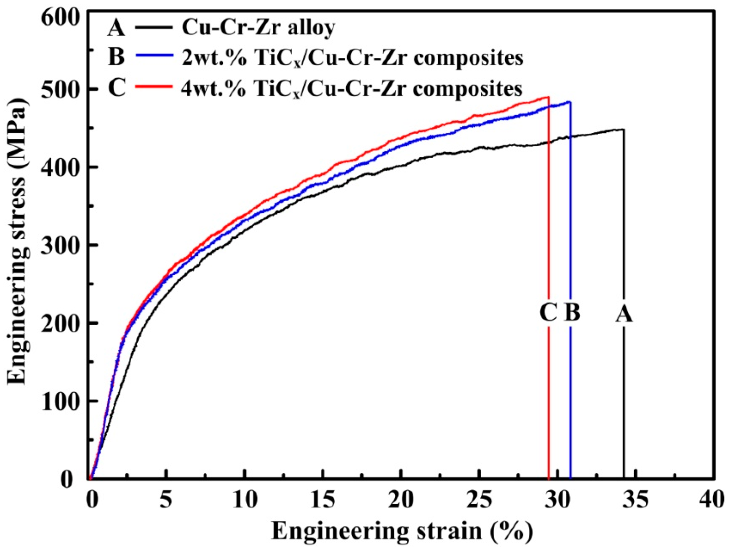
Figure 4 shows the engineering stress-strain curves of compressive test for Cu–Cr–Zr alloys and nano-sized TiCp-reinforced Cu–Cr–Zr composites with different TiCp content. The compressive test data are presented in Table 1. As exhibited in the diagram, the yield strength (σ0.2), ultimate compressive strength (σUCS) and microhardness (HV) of Cu–Cr–Zr alloys were obviously enhanced at the expense of the fracture strain (εf) because of the addition of TiCp. For the nano-sized TiCp-reinforced Cu–Cr–Zr composites, the σ0.2, σUCS and microhardness increased with the increasing TiCp content. The 4-wt% TiCp-reinforced Cu–Cr–Zr composites possessed the highest yield strength (σ0.2), ultimate compressive strength (σUCS) and microhardness (HV), which are 190 MPa, 491 MPa and 118.5 HV, respectively. The fracture strain (εf) of Cu–Cr–Zr alloys, 2-wt % and 4-wt % nano-sized TiCp-reinforced Cu–Cr–Zr composites are 34.1%, 30.7% and 29.3%, respectively.
As we know, the metal matrix determined the ductility of the composites and the ceramic particles determined the strength of the composites [46]. The fracture surface of (a) Cu–Cr–Zr alloys, (b) 2-wt % nano-sized TiCp/Cu–Cr–Zr composites and (c) 4-wt % nano-sized TiCp/Cu–Cr–Zr composites were shown in Figure 5. As can be seen, the fracture surface of Cu–Cr–Zr alloys consists of dimples, which means that the Cu–Cr–Zr alloy has a good plasticity. With the addition of TiCp, the amount of dimples decreased and some TiCp clusters appeared in the dimples. Uniformly dispersed TiCp can improve the mechanical properties of the Cu–Cr–Zr alloys, but cluster of TiCp will act as the source of crack leading to the reduction of the plasticity. This means that the additon of TiCp can improve the strength of composite but sacrifice the plasticity. According to the above viewpoint, we conject that the σ0.2, σUCS and microhardness could be enhanced and the fracture strain (εf) decreased with the increasing TiCp content. Consequently, the 4-wt % TiCp-reinforced Cu–Cr–Zr composites possessed the highest compression strength and microhardness (HV).
The variation in volume loss with different abrasive particles of 6.5 μm, 10.3 μm and 13 μm at the applied load of 5 N for the Cu–Cr–Zr alloys, 2-wt % and 4-wt % nano-sized TiCp-reinforced Cu–Cr–Zr composites are shown in Figure 6. As indicated, the volume loss of the alloys and composites increased with the increasing abrasive particles. This may be due to the large abrasive particles that penetrated deeply into contact area of the alloys and the composites, leading to the increase in volume loss of composites. Meanwhile, the volume loss of the Cu–Cr–Zr alloys, 2-wt % and 4-wt % TiCp-reinforced Cu–Cr–Zr composites decreased with the increasing TiCp content under all abrasive particles. The reason may be the grain refinement, nano-sized particle strengthening and the good interface bonding of composites, which could enhance the hardness and decrease the volume loss of composites. It also can be confirmed by the SEM images of the worn surfaces for Cu–Cr–Zr alloys, 2-wt % and 4-wt % nano-sized TiCp-reinforced Cu–Cr–Zr composites at 13 μm abrasive particles, as shown in Figure 7.
SiC particles penetrated deeply into the contact area of Cu–Cr–Zr alloys and these abrasive particles (Figure 7a) lead to the deformation of the surfaces of the alloys. The surfaces, after wear and tear of TiCp-reinforced Cu–Cr–Zr composites, became smooth with the increasing nano-sized TiCp contents (Figure 7b,c). As already discussed, microhardness of the TiCp-reinforced Cu–Cr–Zr composites can be improved with an increase in particle content. Therefore, the depth of abrasive particles penetrated into the composites decreased with the increasing hardness. Accordingly, it is evident that TiCp can effectively enhance the microhardness and wear resistance by dispersing TiCp into Cu matrix, in which TiCp played a role as grain refinement in enhancing the composites and a barrier in reducing the cutting efficiency of abrasive particles as well as hammering the deformation of the Cu matrix. Accordingly, the wear resistance of the TiCp-reinforced Cu–Cr–Zr composites was enhanced due to the addition of TiCp.
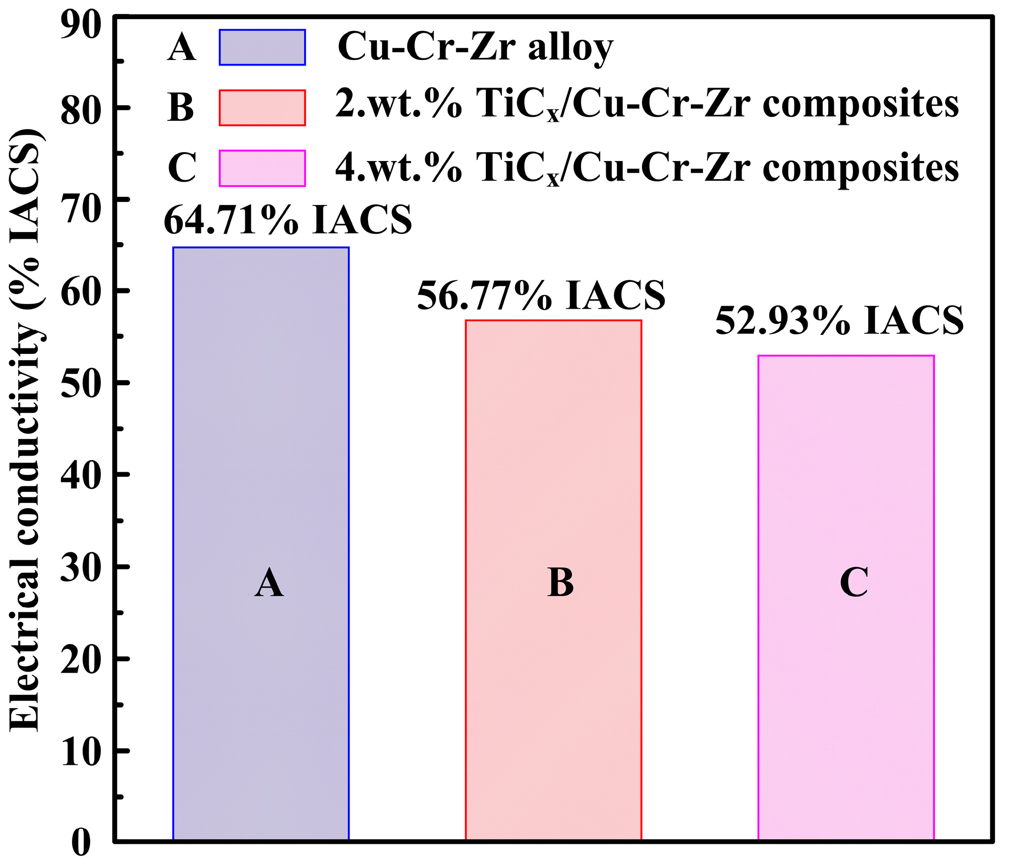
Figure 8 shows the electrical conductivity of Cu–Cr–Zr alloys and nano-sized TiCp-reinforced Cu–Cr–Zr composites with different TiCp content. As indicated, their electrical conductivities are 64.71%, 56.77% and 52.93% IACS, respectively. The electrical conductivities decrease with the addition of TiCp, which are in the order of Cu–Cr–Zr alloys > 2-wt % TiCp-reinforced Cu–Cr–Zr composites > 4-wt % TiCp-reinforced Cu–Cr–Zr composites.
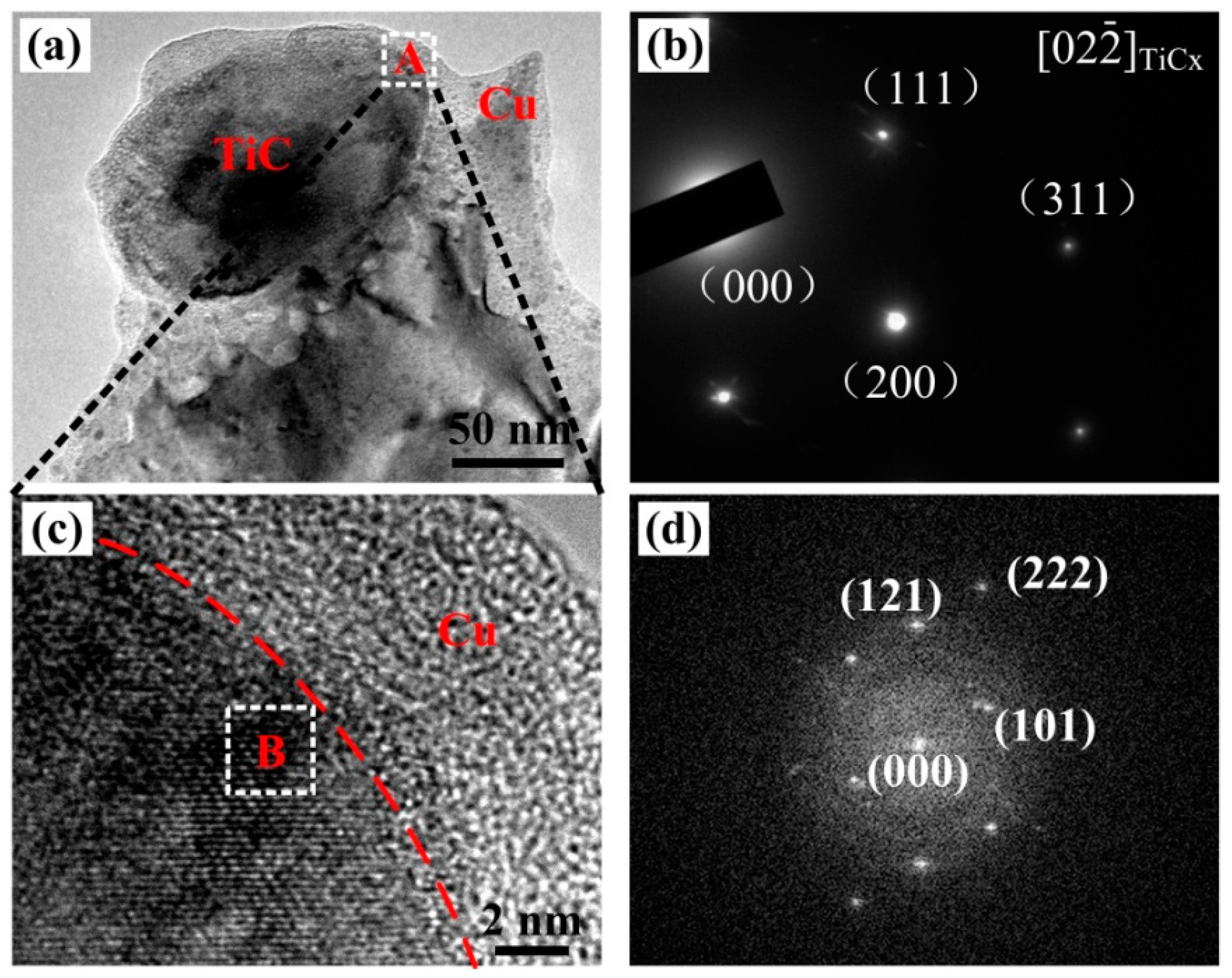
Wetting angle (θ) was a standard to measure whether the reinforced particles can be act as the heterogeneous nuclei to refine the grain during the crystallization of Cu melt. Small wetting angle (0° < θ < 90°) can provide the potential to act as the heterogeneous nuclei and high wetting angle (90° < θ < 180°) can not. TiCp and Cu have a high wetting angle that belongs to non-wetting system. Accordingly, the TiCp could not act as the heterogeneous nuclei to refine the grain of Cu–Cr–Zr alloy. For the purpose of studying the grain refining mechanism of Cu–Cr–Zr alloys, we therefore studied the interfaces between TiCp and Cu nmatrix in the TiCp-reinforced Cu–Cr–Zr composites. Figure 9 shows TEM images of 4 wt % nano-sized TiCp-reinforced Cu–Cr–Zr composites. As indicated in Figure 9a, nano-sized TiCp can be seen clearly in the Cu composites. The electron diffraction pattern image of marked area in Figure 9b corresponds to the [02] zone axis on TiCp in Figure 9a. The HRTEM image (Figure 9c) of area A in Figure 9a and the fast-Fourier-filtered (FFT) images (Figure 9d) of selected area in Figure 9c are consistent with the [10] zone axis of Cu3Ti. The lattice vectors (a, b, and c) of space group (Pmmn) belonging to Cu3Ti (Pmmn, a = 5.162 nm, b = 4.347 nm, c = 4.531 nm) can be calculated and confirmed around the TiCp according to the HRTEM and FFT. A layer of Cu3Ti existed between the TiCp and the Cu–Cr–Zr matrix and a good interfacial bonding in the HRTEM were presented between nano-sized TiCp and Cu–Cr–Zr matrix. Fan et al. [47] confirmed that the free Ti in the melt was conducive to the formation of Cu3Ti layer. Moreover, Yang et al. [48] indicated that the wear resistance could be improved for the good interface bonding of reinforced particles and the matrix in the composites.
Lattice misfit (δ) used to judge the possibility of the heterogeneous nuclei can be calculated by the flowing mathematical model [49]:
where the (hkl)s and (hkl)n are the low index crystal face of the nucleus and the matrix; [uvw]s and [uvw]n are the low index crystal orientation in the (hkl)s and (hkl)n; d[uvw]s and d[uvw]n are the atom space along the direction of the [uvw]s and [uvw]n; θ is the angle between [uvw]s and [uvw]n.
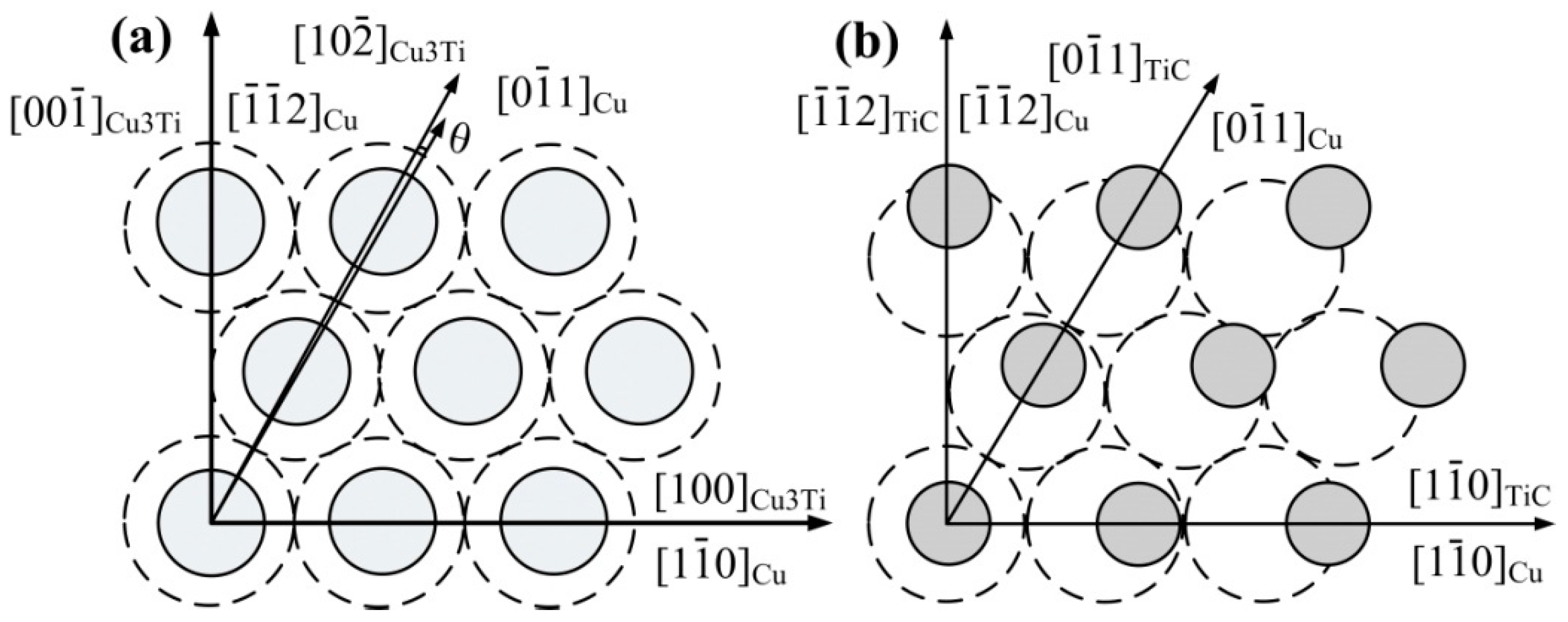
The crystallographic relationships for Cu3Ti and Cu as well as TiCp and Cu are shown in Figure 10. The (111) of Cu is superimposed on the (010) of Cu3Ti, as shown in Figure 10a. The low index crystal faces of Cu are [10], [01] and [2], and that of Cu3Ti are [100], [10] and [00]. The angle between [01] of Cu and [10] of Cu3Ti is 0.33°. The low index crystal faces of Cu3Ti are [010], [01] and [00], and that of TiC are [001], [011] and [00]. The angles are 0°, 0.7884° and 0°, respectively.
Table 2 shows the calculated results of lattice misfit using Equation (1). As shown in Table 2, the lattice misfit (δ) between the (111) of Cu and the (010) of Cu3Ti is 1.9%, indicating that Cu3Ti could act as the heterogeneous nuclei during the crystallization of Cu-melt. On the other hand, the lattice misfit (δ) between the (100) of Cu3Ti and the (100) of TiC is 1.2%. The low lattice misfit (δ) between Cu3Ti and Cu as well as Cu3Ti and TiCp is conducive to good interface bonding. According to the reaction mechanism in Cu–Ti–CNTs system [25], Cu firstly reacts with Ti to form TixCuy around Ti particles. With increasing temperature, TixCuy melts to form a Cu–Ti binary liquid phase, meanwhile, CNTs dissolve in the Cu–Ti binary liquid phase to form an Cu–Ti–C ternary liquid phase. When the concentration of [Ti] and [C] in the Cu–Ti–C ternary liquid phase is high enough for reactions between [Ti] and [C] to occur, TiCx will be synthesized and precipitate out of the melts. However, the reaction is not complete; TixCuy will be remaining in the TiCx/Cu master alloy. When the master alloy remelts and is dispersed into the melting Cu–Cr–Zr alloys, the Cu3Ti layer formed by the adsorption of Ti atoms from Cu–Ti solution, and the Cu3Ti could even exist at lower concentration or at the temperature above the alloy liquidus. Therefore, the formation of Cu3Ti is mainly because of the reduction of the interfacial energy at the interface between TiCp and the Cu-melt. As a result, Cu3Ti formed surrounding the TiCp as the heterogeneous nuclei refined the grain.
As already discussed, the grain refinement of Cu–Cr–Zr alloy is caused by the Cu3Ti, which formed on the surface of TiCp. TiCp with a Cu3Ti layer could be used as the heterogeneous nuclei of the Cu-melt. The refinement of grain, nano-sized particle strengthening and good interface bonding improved the ultimate compressive strength (σUCS), yield strength (σ0.2), microhardness (HV) and wear resistance of different TiCp-content reinforced Cu–Cr–Zr composites with a slight decrease in fracture strain (εf) and electrical conductivity.
4. Conclusions
The compressive properties, wear resistance and electrical conductivities of Cu–Cr–Zr alloys and TiCp-reinforced Cu–Cr–Zr composites fabricated via thermal explosion combined with stirring casting were investigated. The results show that nano-sized TiCp can effectively refine the grain of Cu–Cr–Zr alloys. Nano-sized TiCp was surrounded by a layer of Cu3Ti, which played a role as heterogeneous nuclei of Cu. The microstructure of Cu–Cr–Zr composites changed from dendritic grain to equiaxed crystal with the addition of TiCp/Cu master alloy. The grain size decreased from 82 to 28 μm with the increasing TiCp content. Compared with Cu–Cr–Zr alloys, the ultimate compressive strength (σUCS), yield strength (σ0.2) and hardness (HV) of nano-sized TiCp-reinforced Cu–Cr–Zr composites were improved. The wear resistance of Cu–Cr–Zr alloys and TiCp-reinforced Cu–Cr–Zr composites increased with the increasing content of TiCp. The refinement of grain, nano-sized particle strengthening and the good interface bonding improved the strength, hardness and wear resistance of Cu–Cr–Zr alloys and nano-sized TiCp-reinforced Cu–Cr–Zr composites with different particle content.
Acknowledgments
This work is supported by the National Natural Science Foundation of China (NNSFC, No. 51571101). Partial financial supports come from the “twelfth five-year plan” Science & Technology Research Foundation of Education Bureau of Jilin Province, China (Grant No.2015-478), and the Project 985-High Properties Materials of Jilin University.
Author Contributions
Dongdong Zhang and Jinguo Wang conceived and designed the experiments; Dongdong Zhang, Fang Bai and Yong Wang performed the experiments; Wenquan Wang contributed reagents/materials/analysis tools; Dongdong Zhang, Jinguo Wang and Wenquan Wang analyzed the data; Dongdong Zhang wrote the paper.
Conflicts of Interest
The authors declare no conflicts of interest.
References
- Purcek, G.; Yanar, H.; Saray, O.; Karaman, I.; Maier, H.J. Effect of precipitation on mechanical and wear properties of ultrafine-grained Cu-Cr-Zr alloy. Wear 2014, 311, 149–158. [Google Scholar] [CrossRef]
- Zhang, B.; Zhang, Z.G.; Li, W. Effects of thermo-mechanical treatment on microstructure and properties of Cu-Cr-Zr alloys. Phys. Procedia 2013, 50, 55–60. [Google Scholar] [CrossRef]
- Batra, I.S.; Dey, G.K.; Kulkarni, U.D.; Banerjee, S. Microstructure and properties of a Cu-Cr-Zr alloy. J. Nucl. Mater. 2001, 299, 91–100. [Google Scholar] [CrossRef]
- Mishnev, R.; Shakhova, I.; Belyakov, A.; Kaibyshev, R. Deformation microstructures, strengthening mechanisms, and electrical conductivity in a Cu-Cr-Zr alloy. Mater. Sci. Eng. A 2015, 629, 29–40. [Google Scholar] [CrossRef]
- Ryu, H.J.; Baik, H.K.; Hong, S.H. Effect of thermomechanical treatments on microstructure and properties of Cu-base leadframe alloy. J. Mater. Sci. 2000, 35, 3641–3646. [Google Scholar] [CrossRef]
- Zhilyaev, A.P.; Shakhova, I.; Morozova, A.; Belyakov, A.; Kaibyshev, R. Grain refinement kinetics and strengthening mechanisms in Cu-0.3Cr-0.5Zr alloy subjected to intense plastic deformation. Mater. Sci. Eng. A 2016, 654, 131–142. [Google Scholar] [CrossRef]
- Oanh, N.T.H.; Viet, N.H.; Kim, J.S.; Junior, A.M.J. Characterization of In-Situ Cu-TiH2-C and Cu-Ti-C Nanocomposites Produced by Mechanical Millingand Spark Plasma Sintering. Metals 2017, 7, 117. [Google Scholar] [CrossRef]
- Rajkumar, K.; Aravindan, S. Tribological performance of microwave sintered copper-TiC-graphite hybrid composites. Tribol. Int. 2011, 44, 347–358. [Google Scholar] [CrossRef]
- Guo, M.X.; Wang, M.P.; Shen, K. Synthesis of nano TiB2 particles in copper matrix by in situ reaction of double-beam melts. J. Alloys Compd. 2008, 460, 585–589. [Google Scholar] [CrossRef]
- Akhtar, F.; Askari, S.J.; Shah, K.A.; Du, X.L.; Guo, S.J. Microstructure, mechanical properties, electrical conductivity and wear behavior of high volume TiC reinforced Cu-matrix composites. Mater. Charact. 2009, 60, 327–366. [Google Scholar] [CrossRef]
- Liu, Q.; He, X.B.; Ren, S.B.; Liu, T.T.; Kang, Q.P.; Qu, X.H. Fabrication and thermal conductivity of copper matrix composites reinforced with Mo2C or TiC coated graphite fiber. Mater. Res. Bull. 2013, 48, 4811–4817. [Google Scholar] [CrossRef]
- Qiu, F.; Han, Y.; Cheng, A.; Lu, J.B.; Jiang, Q.C. Effect of Cr Content on the Compression Properties and Abrasive Wear Behavior of the High-Volume Fraction (TiC–TiB2)/Cu Composites. Acta Metall. Sin. 2014, 27, 951–956. [Google Scholar] [CrossRef]
- Qiu, F.; Chu, J.G.; Hu, W.; Lu, J.B.; Li, X.D.; Han, Y.; Jiang, Q.C. Study of effect of Zr addition on the microstructures and mechanical properties of (TiCx–TiB2)/Cu composites by combustion synthesis and hot press consolidation in the Cu-Ti-B4C-Zr system. Mater. Res. Bull. 2015, 70, 167–172. [Google Scholar] [CrossRef]
- Shojaeepour, F.; Abachi, P.; Purazrang, K.; Moghanian, A.H. Production and properties of Cu/Cr2O3 nano-composites. Powder Technol. 2012, 222, 80–84. [Google Scholar] [CrossRef]
- Lu, J.B.; Shu, S.L.; Qiu, F.; Wang, Y.W.; Jiang, Q.C. Compression properties and abrasive wear behavior of high volume fraction TiCx–TiB2/Cu composites fabricated by combustion synthesis and hot press consolidation. Mater. Des. 2012, 40, 157–162. [Google Scholar] [CrossRef]
- Storms, E.K. The Refractory Carbides; Academic Press: New York, NY, USA, 1967. [Google Scholar]
- Rahaei, M.B.; Yazdanirad, R.; Kazemzadeh, A.; Ebadzadeh, T. Mechanochemical synthesis of nano TiC powder by mechanical milling of titanium and graphite powders. Powder Technol. 2012, 217, 369–376. [Google Scholar] [CrossRef]
- Yang, Y.F.; Mu, D.K.; Jiang, Q.C. A simple route to fabricate TiC–TiB2/Ni composite via thermal explosion reaction assisted with external pressure in air. Mater. Chem. Phys. 2014, 143, 480–485. [Google Scholar] [CrossRef]
- Klinger, L.; Gotman, I.; Horvitz, D. In-situ processing of TiB2: TiC ceramic composites by thermal explosion under pressure: Experimental study and modeling. Mater. Sci. Eng. A 2001, 302, 92–99. [Google Scholar] [CrossRef]
- Lin, Q.L.; Shen, P.; Yang, L.L.; Jin, S.B.; Jiang, Q.C. Wetting of TiC by molten Al at 1123–1323 K. Acta Mater. 2011, 59, 1898–1911. [Google Scholar] [CrossRef]
- Yang, Y.F.; Jiang, Q.C. Effect of TiB2/TiC ratio on the microstructure and mechanical properties of high volume fractions of TiB2/TiC reinforced Fe matrix composite. Int. J. Refract. Met. Hard Mater. 2013, 38, 137–139. [Google Scholar] [CrossRef]
- Zhao, Q.; Liang, Y.H.; Zhang, Z.H.; Li, X.J.; Ren, L.Q. Study on the Impact Resistance of Bionic Layered Composite of TiC–TiB2/Al from Al-Ti-B4C System. Materials 2016, 9, 708. [Google Scholar] [CrossRef] [PubMed]
- Zhou, D.S.; Qiu, F.; Wang, H.Y.; Jiang, Q.C. Manufacture of Nano-Sized Particle-Reinforced Metal Matrix Composites: A Review. Acta Metall. Sin. 2014, 27, 798–805. [Google Scholar] [CrossRef]
- Wang, L.; Qiu, F.; Zhao, Q.L.; Wang, H.Y.; Yang, D.L.; Jiang, Q.C. Simultaneously increasing the elevated-temperature tensile strength and plasticity of in-situ nano-sized TiCx/Al-Cu-Mg composites. Mater. Charact. 2017, 125, 7–12. [Google Scholar] [CrossRef]
- Liang, Y.H.; Zhao, Q.; Li, X.J.; Zhang, Z.H.; Ren, L.Q. Effect of Ti and C particle size on reaction behavior of thermal explosion (TE) reaction of Cu-Ti-C system under Ar and air atmosphere. J. Alloys Compd. 2016, 679, 65–73. [Google Scholar] [CrossRef]
- Popov, V.A.; Shelekhov, E.V.; Prosviryakov, A.S.; Presniakov, M.Y.; Senatulin, B.R.; Kotov, A.D.; Khomutov, M.G. Particulate metal matrix composites development on the basis of in-situ synthesis of TiC reinforcing nanoparticles during mechanical alloying. J. Alloys Compd. 2017, 707, 365–370. [Google Scholar] [CrossRef]
- Jin, S.B.; Shen, P.; Zou, B.L.; Jiang, Q.C. Morphology Evolution of TiCx Grains during SHS in an Al-Ti-C System. Cryst. Growth Des. 2009, 9, 646–649. [Google Scholar] [CrossRef]
- Shu, S.L.; Tong, C.Z.; Qiu, F.; Jiang, Q.C. Effect of Ceramic Content on the Compression Properties of TiB2-Ti2AlC/TiAl Composites. Metals 2015, 5, 2200–2209. [Google Scholar] [CrossRef]
- Tian, W.S.; Zhou, D.S.; Qiu, F.; Jiang, Q.C. Superior tensile properties of in situ nano-sized TiCp/Al-Cu composites fabricated by reaction in melt method. Mater. Sci. Eng. A 2016, 658, 409–414. [Google Scholar] [CrossRef]
- Wang, L.; Qiu, F.; Zhao, Q.L.; Zha, M.; Jiang, Q.C. Superior high creep resistance of in situ nano-sized TiCx/Al-Cu-Mg composite. Sci. Rep. 2017, 7, 4540. [Google Scholar] [CrossRef] [PubMed]
- Qiu, F.; Gao, Y.Y.; Liu, J.Y.; Shu, S.L.; Zou, Q.; Zhang, T.Z.; Jiang, Q.C. Effect of reactant C/Ti ratio on the compressive properties and wear properties of the 50 vol % submicron-sized TiCx/2014Al composites fabricated by combustion synthesis and hot press consolidation. Powder Metall. 2016, 59, 256–261. [Google Scholar] [CrossRef]
- Yang, Y.F.; Jiang, Q.C. Reaction behaviour, microstructure and mechanical properties of TiC-TiB2/Ni composite fabricated by pressure assisted self-propagating high-temperature synthesis in air and vacuum. Mater. Des. 2013, 49, 123–129. [Google Scholar] [CrossRef]
- Wang, L.; Qiu, F.; Shu, S.L.; Zhao, Q.L.; Jiang, Q.C. Effects of different carbon sources on the compressive properties of in situ high-volume-fraction TiCx/2009Al composites. Powder Metall. 2016, 59, 370–375. [Google Scholar] [CrossRef]
- Zhang, D.D.; Bai, F.; Sun, L.P.; Wang, Y.; Wang, J.G. Compression properties and electrical conductivity of in-situ 20 vol % nano-sized TiCx/Cu composites with different particle size and morphology. Materials 2017, 10, 499. [Google Scholar] [CrossRef] [PubMed]
- Zhou, D.S.; Qiu, F.; Jiang, Q.C. Simultaneously increasing thestrength and ductility of nano-sized TiN particle reinforced Al-Cu matrix composites. Mater. Sci. Eng. A 2014, 596, 98–102. [Google Scholar] [CrossRef]
- Zhou, D.S.; Qiu, F.; Jiang, Q.C. The nano-sized TiC particle reinforced Al-Cu composite with superior tensile ductility. Mater. Sci. Eng. A 2015, 622, 189–193. [Google Scholar] [CrossRef]
- Qiu, F.; He, Y.; Zhu, L.; Shu, S.L.; Hu, W.; Zhan, C.H.; Jiang, Q.C. Microstructure and compression properties of in-situ dual phase nano-sized (TiB2-Ti5Si3)/TiAl matrix composites fabricated by combustion synthesis and hot press consolidation. Powder Metall. 2015, 58, 235–240. [Google Scholar] [CrossRef]
- Qiu, F.; Zuo, R.; Shu, S.L.; Wang, T.W.; Jiang, Q.C. Effect of Al addition on the microstructures and compression properties of (TiCxNy-TiB2)/Ni composites fabricated by combustion synthesis and hot press. Powder Technol. 2015, 286, 716–721. [Google Scholar] [CrossRef]
- Wang, L.; Qiu, F.; Ouyang, L.C.; Wang, H.Y.; Zha, M.; Shu, S.L.; Zhao, Q.L.; Jiang, Q.C. A Novel Approach of Using Ground CNTs as the Carbon Source to Fabricate Uniformly Distributed Nano-Sized TiCx/2009Al Composites. Materials 2015, 8, 8839–8849. [Google Scholar] [CrossRef]
- Wang, L.; Qiu, F.; Liu, J.Y.; Wang, H.Y.; Wang, J.G.; Zhu, L.; Jiang, Q.C. Microstructure and tensile properties of in situ synthesized nano-sized TiCx/2009Al composites. Mater. Des. 2015, 79, 68–72. [Google Scholar] [CrossRef]
- Qiu, F.; Gao, X.; Tang, J.; Gao, Y.Y.; Shu, S.L.; Han, X.; Li, Q.; Jiang, Q.C. Microstructures and Tensile Properties of Al–Cu Matrix Composites Reinforced with Nano-Sized SiCp Fabricated by Semisolid Stirring Process. Metals 2017, 7, 49. [Google Scholar] [CrossRef]
- Liang, Y.H.; Han, Z.W.; Lin, Z.H.; Ren, L.Q. Study on the reaction behavior of self-propagating high-temperature synthesis of TiC ceramic in the Cu-Ti-C system. Int. J. Refract. Met. Hard Mater. 2012, 137, 221–227. [Google Scholar] [CrossRef]
- Zarrinfar, N.; Kennedy, A.R.; Shipway, P.H. Reaction synthesis of Cu-TiCx master-alloys for the production of copper-based composites. Scr. Mater. 2004, 50, 949–952. [Google Scholar] [CrossRef]
- Jha, P.; Gautam, R.K.; Tyagi, R.; Kumar, D. Sliding wear behavior of TiC-reinforced Cu-4 wt % Ni matrix composites. J. Mater. Eng. Perform. 2016, 25, 4210–4218. [Google Scholar] [CrossRef]
- Dudiy, S.V.; Lundqvist, B.I. Wetting of TiC and TiN by metals. Phys. Rev. B 2004, 69, 125421. [Google Scholar] [CrossRef]
- Shu, S.L.; Yang, H.Y.; Tong, C.Z.; Qiu, F. Fabrication of TiCx-TiB2/Al Composites for Application as a Heat Sink. Materials 2016, 9, 642. [Google Scholar] [CrossRef] [PubMed]
- Fan, Z.; Wang, Y.; Qin, T.; Zhou, X.R.; Thompson, G.E.; Pennycook, T.; Hashimoto, T. Grain refining mechanism in the Al/Al-Ti-B system. Acta Mater. 2015, 84, 292–304. [Google Scholar] [CrossRef]
- Yang, D.L.; Qiu, F.; Zhao, Q.L.; Wang, L.; Jiang, Q.C. The abrasive wear behavior of Al2014 composites reinforced with Ti5Si3-coated SiCp. Tribol. Int. 2017, 112, 33–41. [Google Scholar] [CrossRef]
- Xu, Z.M.; Liang, G.F.; Guan, Q.F.; Jiang, Q.C. TiC as heterogeneous nuclei of the (Fe, Mn) 3C and austenite intergrowth eutectic in austenite steel matrix wear resistant composite. Mater. Res. Bull. 2004, 39, 457–463. [Google Scholar]
Figure 1.
XRD patterns of Cu–Ti–CNTs master alloy after combustion synthesis.

Figure 2.
(a) Morphology of the deep etched surfaces of the master alloy, (b) the TiCp extracted from the TiCp/Cu master alloy, (c) size distribution of extracted TiCp and (d) enlarged image corresponding to selected area.
Figure 2.
(a) Morphology of the deep etched surfaces of the master alloy, (b) the TiCp extracted from the TiCp/Cu master alloy, (c) size distribution of extracted TiCp and (d) enlarged image corresponding to selected area.

Figure 3.
The morphologies of grain in (a) Cu–Cr–Zr alloys, (b) 2-wt %, (c) 4-wt % nano-sized TiCp-reinforced Cu–Cr–Zr composites and (d–f) the corresponding grain size distribution.
Figure 3.
The morphologies of grain in (a) Cu–Cr–Zr alloys, (b) 2-wt %, (c) 4-wt % nano-sized TiCp-reinforced Cu–Cr–Zr composites and (d–f) the corresponding grain size distribution.

Figure 4.
Engineering stress-strain curves of compressive test for (A) Cu–Cr–Zr alloys, (B) 2-wt % and (C) 4-wt % nano-sized TiCp-reinforced Cu–Cr–Zr composites
Figure 4.
Engineering stress-strain curves of compressive test for (A) Cu–Cr–Zr alloys, (B) 2-wt % and (C) 4-wt % nano-sized TiCp-reinforced Cu–Cr–Zr composites

Figure 5.
The fracture surface of (a) Cu–Cr–Zr alloys, (b) 2-wt % nano-sized TiCp/Cu–Cr–Zr composites and (c) 4-wt % nano-sized TiCp/Cu–Cr–Zr composites.
Figure 5.
The fracture surface of (a) Cu–Cr–Zr alloys, (b) 2-wt % nano-sized TiCp/Cu–Cr–Zr composites and (c) 4-wt % nano-sized TiCp/Cu–Cr–Zr composites.
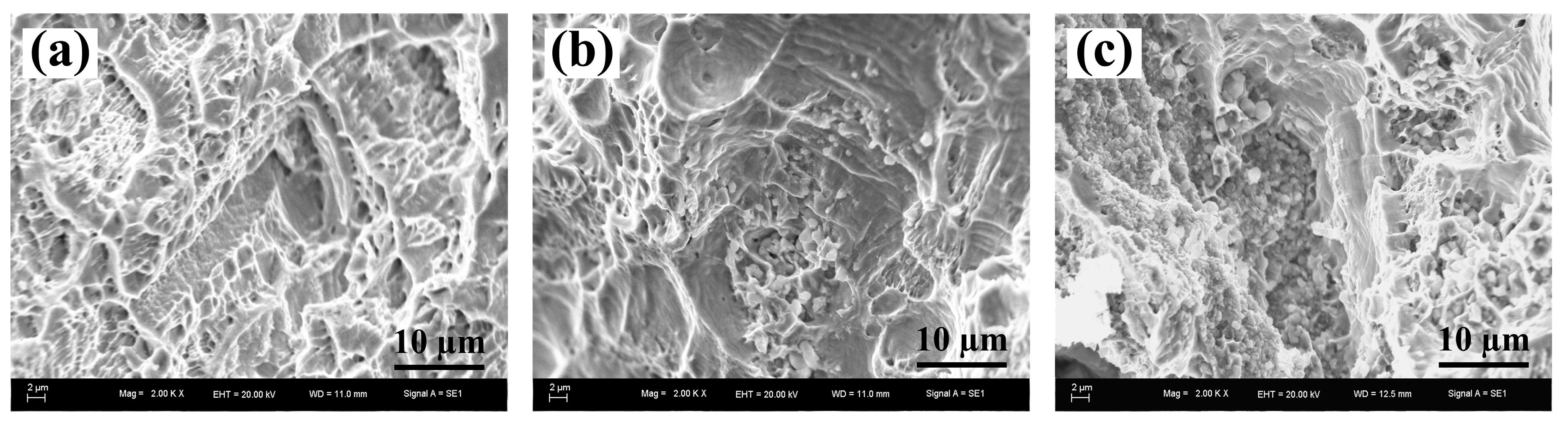
Figure 6.
Volume loss against different abrasive particles of 6.5 μm, 10.3 μm and 13 μm at the applied load of 5N for the Cu–Cr–Zr alloys and nano-sized TiCp-reinforced Cu–Cr–Zr composites.
Figure 6.
Volume loss against different abrasive particles of 6.5 μm, 10.3 μm and 13 μm at the applied load of 5N for the Cu–Cr–Zr alloys and nano-sized TiCp-reinforced Cu–Cr–Zr composites.
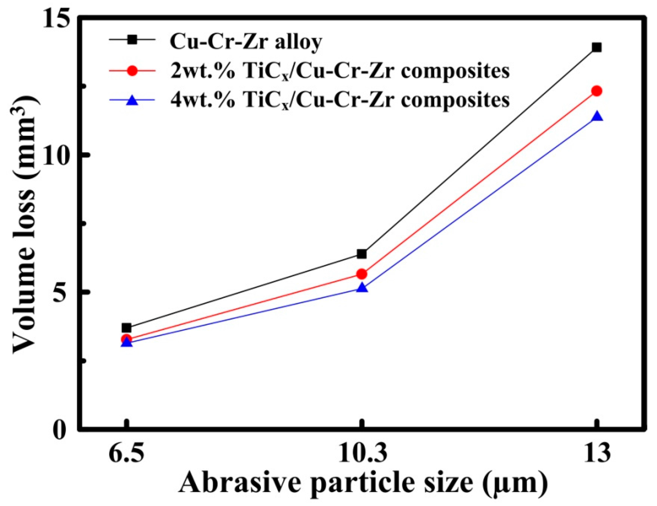
Figure 7.
The morphologies of the worn surfaces for (a) Cu–Cr–Zr alloys, (b) 2-wt % and (c) 4-wt % nano-sized TiCp-reinforced Cu–Cr–Zr comp osites at 13 μm abrasive particles.
Figure 7.
The morphologies of the worn surfaces for (a) Cu–Cr–Zr alloys, (b) 2-wt % and (c) 4-wt % nano-sized TiCp-reinforced Cu–Cr–Zr comp osites at 13 μm abrasive particles.
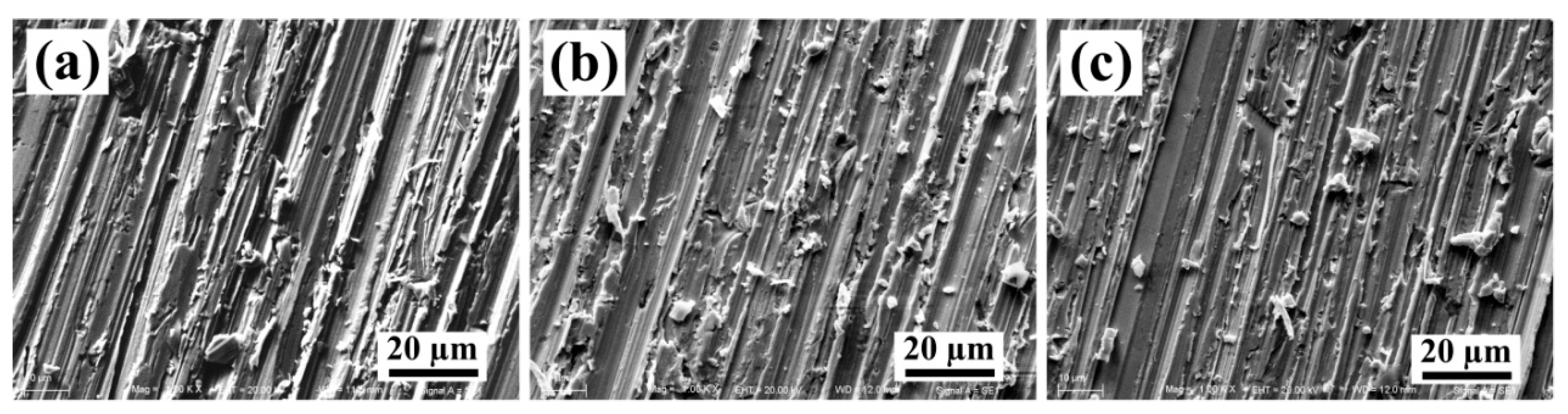
Figure 8.
The electrical conductivity of Cu–Cr–Zr alloys and TiCp-reinforced Cu–Cr–Zr composites.

Figure 9.
(a) TEM images of 4 wt % nano-sized TiCp-reinforced Cu–Cr–Zr composites, (b) the images of TiCp electron diffraction pattern, (c) the HRTEM image corresponding to area A, and (d) the FFT images corresponding to area B.
Figure 9.
(a) TEM images of 4 wt % nano-sized TiCp-reinforced Cu–Cr–Zr composites, (b) the images of TiCp electron diffraction pattern, (c) the HRTEM image corresponding to area A, and (d) the FFT images corresponding to area B.

Figure 10.
Crystallographic relationship. (a) (010) Cu3Ti and (111) Cu faces, (b) (111)TiC and (111)Cu faces.
Figure 10.
Crystallographic relationship. (a) (010) Cu3Ti and (111) Cu faces, (b) (111)TiC and (111)Cu faces.

Table 1.
Compressive properties of the Cu–Cr–Zr alloys, 2-wt % and 4-wt % TiCp-reinforced Cu–Cr–Zr composites.
Table 1.
Compressive properties of the Cu–Cr–Zr alloys, 2-wt % and 4-wt % TiCp-reinforced Cu–Cr–Zr composites.
| Samples | σ0.2/MPa | σUCS/MPa | εf/% | Hardness (HV) |
|---|---|---|---|---|
| Cu–Cr–Zr alloys | 97.1 | |||
| 2-wt % TiCp/Cu–Cr–Zr | 112.3 | |||
| 4-wt % TiCp/Cu–Cr–Zr | 118.5 |
Table 2.
The calculated lattice misfit between Cu3Ti and α-Cu phases.
| Matching Plane | [uvw]Cu3Ti | [uvw]Cu | θ (deg) | δ (%) |
|---|---|---|---|---|
| (010)Cu3Ti//(111)Cu | [100]Cu3Ti | [1]Cu | 0 | 1.9 |
| [1]Cu3Ti | [1]Cu | 0.33 | ||
| [00]Cu3Ti | []Cu | 0 | ||
| (111)TiC//(111)Cu | [10]TiC | [1]Cu | 0 | 19.8 |
| [01]TiC | [01]Cu | 0 | ||
| [2]TiC | [2]Cu | 0 | ||
| (100)Cu3Ti//(100)TiC | [010]Cu3Ti | [001]TiC | 0 | 1.2 |
| [01]Cu3Ti | [011]TiC | 0.7884 | ||
| [00]Cu3Ti | [010]TiC | 0 |
© 2017 by the authors. Licensee MDPI, Basel, Switzerland. This article is an open access article distributed under the terms and conditions of the Creative Commons Attribution (CC BY) license (http://creativecommons.org/licenses/by/4.0/).
Share and Cite
MDPI and ACS Style
Zhang, D.; Bai, F.; Wang, Y.; Wang, J.; Wang, W. Grain Refinement and Mechanical Properties of Cu–Cr–Zr Alloys with Different Nano-Sized TiCp Addition. Materials 2017, 10, 919. https://doi.org/10.3390/ma10080919
AMA Style
Zhang D, Bai F, Wang Y, Wang J, Wang W. Grain Refinement and Mechanical Properties of Cu–Cr–Zr Alloys with Different Nano-Sized TiCp Addition. Materials. 2017; 10(8):919. https://doi.org/10.3390/ma10080919
Chicago/Turabian StyleZhang, Dongdong, Fang Bai, Yong Wang, Jinguo Wang, and Wenquan Wang. 2017. "Grain Refinement and Mechanical Properties of Cu–Cr–Zr Alloys with Different Nano-Sized TiCp Addition" Materials 10, no. 8: 919. https://doi.org/10.3390/ma10080919
Note that from the first issue of 2016, this journal uses article numbers instead of page numbers. See further details here.