Research on Formation Conditions of the Ultrafine-Grained Structure of the Cylindrical Parts Manufactured by Power Spinning Based on Small Strains


Abstract
:1. Introduction
2. Materials and Methods
2.1. Test Condition
2.2. Modified Williamdon-Hall Method Based on XRD
2.3. Calculation the Average Value of the Contrast Factors
2.4. Calculation of the Parameter q
2.5. Calculation of the Dislocation Density
3. Results and Discussion
3.1. Dislocation Density and Microstructural Evolution
3.2. Formation Condition of the UFG Structure
3.3. Mechanical Properties of the Parts with UFG Structure
4. Conclusions
- (1)
- The required plastic strains can be reduced significantly when manufacturing the parts with a UFG structure by combining power spinning and heat treatment technologies. The required plastic strains are only 2.27 and 0.92 of manufacturing the cylindrical parts with UFG structure by PSA and QPSA, respectively.
- (2)
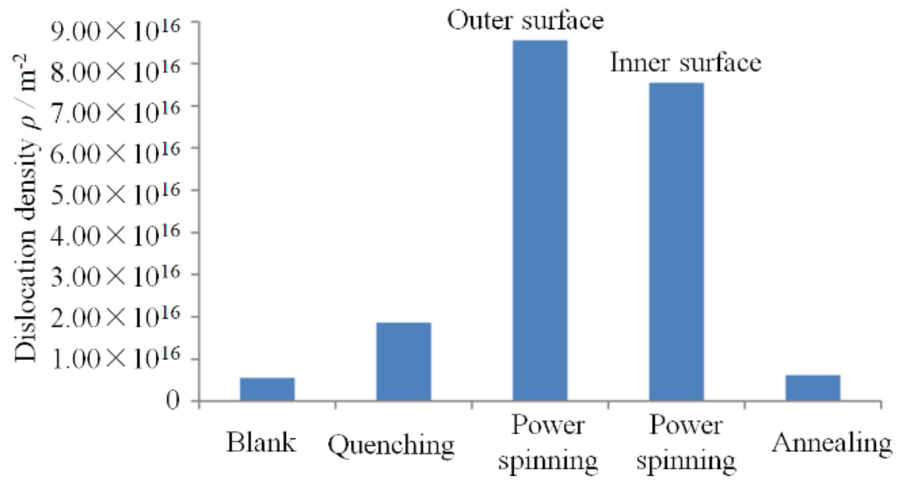
- The dislocation density and storage energy are increased to 10 times that of the blank after quenching and power spinning and decreased to the level of the blank after recrystallization annealing.
- (3)
- The refining degree of the martensite structure during power spinning is much larger than that of the equilibrium structure. The ultrafine dislocation cells are formed in a martensite lath after power spinning and the UFG structure with an average grain size of 160 nm is generated after recrystallization annealing.
- (4)
- The formation conditions for manufacturing the cylindrical parts with a UFG structure based on small strains are as follows: (1) Fine grains and subgrains size obtained during quenching; (2) The storage energy of the workpiece reaches 1.8 × 10⁵ kJ/m3 after power spinning; and (3) Second phase particle with nano-scale is precipitated during recrystallization.
- (5)
- The tensile strength and hardness of the ASTM 1020 spun parts manufactured by the QPSA method are 815 MPa and 305 HV respectively, while the elongation is decreased to 17.5%.
Author Contributions
Funding
Conflicts of Interest
References
- Korznikov, A.; Safarov, I.M.; Galeyev, R.M.; Sergeev, S.N.; Potekaev, A.I. Ultrafine-grained structure and its thermal stability in low-carbon steel. Russ. Phys. J. 2015, 58, 898–903. [Google Scholar] [CrossRef]
- Liu, J.; Deng, X.T.; Huang, L.; Wang, Z.D.; Misra, R.D.K. Mechanical properties and deformation behavior of nano/ultrafine Fe-18Cr-8Ni austenitic steel processed by low temperature rolling and annealing treatment. Steel Res. Int. 2018, 89, 1–9. [Google Scholar] [CrossRef]
- Xu, J.; Li, J.W.; Zhu, X.C.; Fan, G.H.; Shan, D.B.; Guo, B. Microstructural evolution at micro/meso-scale in an ultrafine-grained pure aluminum processed by equal-channel angular pressing with subsequent annealing treatment. Materials 2015, 8, 7447–7460. [Google Scholar] [CrossRef] [PubMed]
- Sun, W.T.; Qiao, X.G.; Zheng, M.Y.; Xu, C.; Kamado, S.; Zhao, X.J.; Chen, H.W.; Gao, N.; Starink, M.J. Altered ageing behavior of a nanostructured Mg-8.2Gd-3.8Y-1.0Zn-0.4Zr alloy processed by high pressure torsion. Acta Mater. 2018, 151, 260–270. [Google Scholar] [CrossRef]
- Aoba, T.; Kobayashi, M.; Miura, H. Microstructural evolution and enhanced mechanical properties by multi-directional forging and aging of 6000 series aluminum alloy. Mater. Trans. 2018, 59, 373–379. [Google Scholar] [CrossRef]
- Alizadeh, M.; Dashtestaninejad, M.K. Development of Cu-matrix, Al/Mn-reinforced, multilayered composites by accumulative roll bonding (ARB). J. Alloys Compd. 2018, 732, 674–682. [Google Scholar] [CrossRef]
- Umemoto, M. Nanocrystallization of steels by severe plastic deformation. Mater. Trans. 2003, 44, 1900–1911. [Google Scholar] [CrossRef]
- Xia, Q.X.; Zhu, N.Y.; Cheng, X.Q.; Xiao, G.F. The classification and A review of hot power spinning of difficult-to-deform metals. Int. J. Mater. Prod. Technol. 2017, 54, 212–235. [Google Scholar] [CrossRef]
- Xia, Q.X.; Xiao, G.F.; Long, H.; Sheng, X.F. A review of process advancement of novel metal spinning. Int. J. Mach. Tools Manuf. 2014, 85, 100–121. [Google Scholar] [CrossRef] [Green Version]
- Xia, Q.X. Novel Spinning Forming Technology; Science Press: Beijing, China, 2017. [Google Scholar]
- Xia, Q.X.; Xiao, G.F.; Long, H.; Yang, B.J. A study of manufacturing tubes with nano/ultrafine grain structure by stagger spinning. Mater. Des. 2014, 59, 516–523. [Google Scholar] [CrossRef] [Green Version]
- Xiao, G.F.; Xia, Q.X.; Cheng, X.Q.; Long, H. New forming method of manufacturing cylindrical parts with nano/ultrafine grained structures based on small strains by power spinning. Sci. China Technol. Sci. 2016, 59, 1656–1665. [Google Scholar] [CrossRef]
- Zheng, R.X.; Bhattacharjee, T.; Shibata, A.; Sasaki, T.; Hono, K.; Joshi, M.; Tsuji, N. Simultaneously enhanced strength and ductility of Mg-Zn-Zr-Ca alloy with fully recrystallized ultrafine grained structures Scr. Mater. 2017, 131, 1–5. [Google Scholar]
- Janeček, M.; Čížek, J.; Gubicza, J.; Vratna, J. Microstructure and dislocation density evolutions in MgAlZn alloy processed by severe plastic deformation. J. Mater. Sci. 2012, 47, 7860–7869. [Google Scholar] [CrossRef]
- Humphreys, F.J.; Hatherly, M. Recrystallization and Related Annealing Phenomena; Elsevier: Holand, The Netherlands, 2004. [Google Scholar]
- Dini, G.; Ueji, R.; Najafizadeh, A.; Monir-Vaghefi, S.M. Flow stress analysis of TWIP steel via the XRD measurement of dislocation density. Mater. Sci. Eng. A 2010, 527, 2759–2763. [Google Scholar] [CrossRef]
- Shintani, T.; Murata, Y. Evaluation of the dislocation density and dislocation character in cold rolled type 304 steel determined by profile analysis of X-ray diffraction. Acta Mater. 2011, 59, 4314–4322. [Google Scholar] [CrossRef]
- Renzetti, R.A.; Sandim, H.R.Z.; Bolmaro, R.E.; Suzuki, P.A.; Möslang, A. X-ray evaluation of dislocation density in ODS-Eurofer steel. Mater. Sci. Eng. A 2012, 534, 142–146. [Google Scholar] [CrossRef]
- Lei, C.Q.; Zhang, J.; Deng, Y.L.; Chen, M.A. The Quantitative research of deformation, dislocation density and dislocation strengthening in Al-Cu-Mg Alloy. Mater. Sci. 2015, 5, 126–133. [Google Scholar]
- Gubicza, J.; Ribárik, G.; Goren-Muginstein, G.R.; Rosen, A.R.; Ungár, T. The density and the character of dislocations in cubic and hexagonal polycrystals determined by X-ray diffraction. Mater. Sci. Eng. A 2001, 309, 60–63. [Google Scholar] [CrossRef]
- Seth, P.P.; Das, A.; Bar, H.N.; Sivaprasad, S.; Basu, A.; Dutta, K. Evolution of dislocation density during tensile deformation of BH220 steel at different pre-strain conditions. J. Mater. Eng. Perform. 2015, 24, 2779–2783. [Google Scholar] [CrossRef]
- Ungár, T.; Dragomir, I.; Révész, Á. The contrast factors of dislocations in cubic crystals: The dislocation model of strain anisotropy in practice. J. Appl. Crystallogr. 1999, 32, 992–1002. [Google Scholar] [CrossRef]
- Zheng, L.; Jiang, C.B.; Shang, J.X.; Zhu, X.X.; Xu, H.B. Calculating elastic constants of Fe-based cubic magnetic material using first principles. Acta Phys. Sin. 2007, 56, 1532–1537. [Google Scholar]
- Xiao, G.F.; Xia, Q.X.; Cheng, X.Q.; Zhou, Y.J. Research on the grain refinement method of cylindrical parts by power spinning. Int. J. Adv. Manuf. Technol. 2015, 78, 1–9. [Google Scholar] [CrossRef]
- Ganeev, A.; Nikitina, M.; Sitdikov, V.; Islamgaliev, R.; Hoffman, A.; Wen, H. Effects of the tempering and high-pressure torsion temperatures on microstructure of ferritic/martensitic steel grade 91. Materials 2018, 11, 627. [Google Scholar] [CrossRef] [PubMed]
- Huang, X.X.; Cai, D.Y.; Yao, M.; Liu, Q.; Hansen, N. Deformation structure and recrystallization behavior of tensile strained copper. Chin. J. Nonferrous Met. 2001, 11, 31–35. [Google Scholar]
- Hansen, H.; Huang, X. Microstructure and flow stress of crystal and polycrystalline. Acta Mater. 1998, 46, 1827–1836. [Google Scholar] [CrossRef]
- Cui, Z.Q.; Qin, Y.C. Metallography and Heat Treatment; China Machine Press: Beijing, China, 2007. [Google Scholar]
- Xiao, G.F.; Xia, Q.X.; Long, J.C.; Chen, W.P. Research on the forming quality and mechanical properties of cylindrical spun parts with ultrafine-grained structure during power spinning. Int. J. Adv. Manuf. Technol. 2018, 97, 2979–2986. [Google Scholar] [CrossRef]
- Sun, C.; Ma, J.; Yang, Y.; Hartwig, K.T.; Maloy, S.A.; Wang, H.; Zhang, X. Temperature and grain size dependent plastic instability and strain rate sensitivity of ultrafine grained austenitic Fe-14Cr-16Ni alloy. Mater. Sci. Eng. A 2014, 597, 415–421. [Google Scholar] [CrossRef]


| Materials | C/% | Si/% | Mn/% | P/% | S/% |
|---|---|---|---|---|---|
| ASTM 1020 | 0.20 | 0.21 | 0.51 | 0.015 | 0.008 |
© 2018 by the authors. Licensee MDPI, Basel, Switzerland. This article is an open access article distributed under the terms and conditions of the Creative Commons Attribution (CC BY) license (http://creativecommons.org/licenses/by/4.0/).
Share and Cite
Xiao, G.; Xia, Q.; Cheng, X.; Chen, W. Research on Formation Conditions of the Ultrafine-Grained Structure of the Cylindrical Parts Manufactured by Power Spinning Based on Small Strains. Materials 2018, 11, 1891. https://doi.org/10.3390/ma11101891
Xiao G, Xia Q, Cheng X, Chen W. Research on Formation Conditions of the Ultrafine-Grained Structure of the Cylindrical Parts Manufactured by Power Spinning Based on Small Strains. Materials. 2018; 11(10):1891. https://doi.org/10.3390/ma11101891
Chicago/Turabian StyleXiao, Gangfeng, Qinxiang Xia, Xiuquan Cheng, and Weiping Chen. 2018. "Research on Formation Conditions of the Ultrafine-Grained Structure of the Cylindrical Parts Manufactured by Power Spinning Based on Small Strains" Materials 11, no. 10: 1891. https://doi.org/10.3390/ma11101891