Effects of the Carbon Fiber-Carbon Microcoil Hybrid Formation on the Effectiveness of Electromagnetic Wave Shielding on Carbon Fibers-Based Fabrics


Abstract
:1. Introduction
2. Materials and Methods
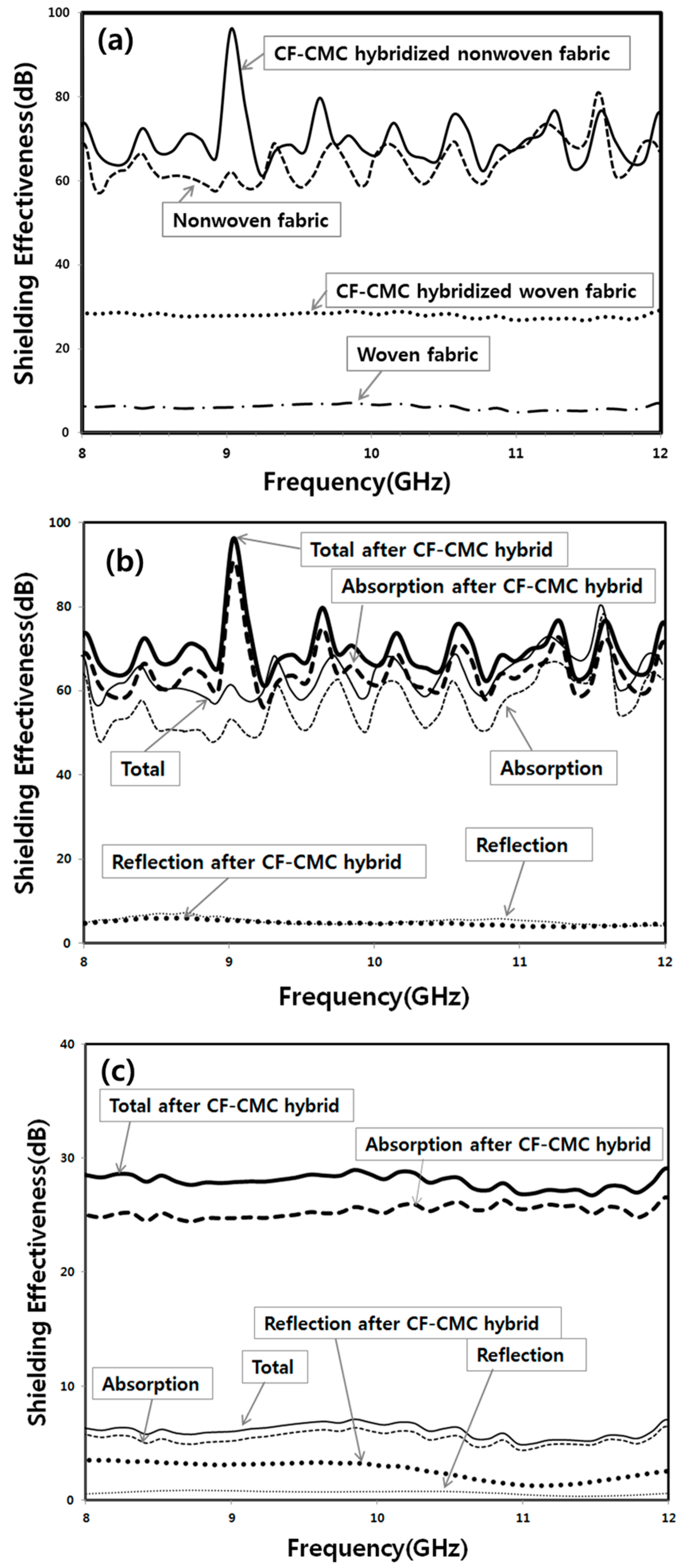
- SETot = 10log (PI/Po) dB.
- SER = −10log (1−R) dB
- SEA = −10log (T/1−R) dB
3. Results and Discussion
4. Conclusions
Author Contributions
Funding
Conflicts of Interest
References
- Wu, J.; Chung, D.L. Increasing the Electromagnetic Interference Shielding Effectiveness of Carbon Fiber Polymer-matrix Composite by Using Activated Carbon Fibers. Carbon 2002, 40, 445–447. [Google Scholar] [CrossRef]
- Chung, D.L. Electromagnetic Interference Shielding Effectiveness of Carbon Materials. Carbon 2001, 39, 279–285. [Google Scholar] [CrossRef]
- Yang, S.; Lozano, K.; Lomeli, A.; Foltz, H.D.; Jones, R. Electromagnetic Interference Shielding Effectiveness of Carbon Nanofiber/LCP Composites. Compos. Part A-Appl. Sci. Manuf. 2005, 36, 691–697. [Google Scholar] [CrossRef]
- Sau, K.P.; Chaki, T.K.; Chakraborty, A.; Khastgir, D. Electromagnetic Interference Shielding by Carbon Black and Carbon Fiber Filled Rubber Composites. Plast. Rubber Compos. Process. Appl. 1997, 26, 291–297. [Google Scholar]
- Motojima, S.; Hoshiya, S.; Hishikawa, Y. Electromagnetic Wave Absorption Properties of Carbon Microcoils/PMMA Composite Beads in W Bands. Carbon 2003, 41, 2658–2660. [Google Scholar] [CrossRef]
- Zhao, D.L.; Shen, Z.M. Preparation and Microwave Absorption Properties of Carbon Nanocoils. Mater. Lett. 2008, 62, 3704–3706. [Google Scholar] [CrossRef]
- Song, W.L.; Wang, J.; Fan, L.Z.; Li, Y.; Wang, C.Y.; Cao, M.S. Interfacial Engineering of Carbon Nanofiber−Graphene−Carbon Nanofiber Heterojunctions in Flexible Lightweight Electromagnetic Shielding Networks. ACS Appl. Mater. Interface 2014, 6, 10516–10523. [Google Scholar] [CrossRef] [PubMed]
- Song, W.L.; Fan, L.Z.; Cao, M.S.; Lu, M.M.; Wang, C.Y. Facile Fabrication of Ultrathin Graphene Papers for Effective Electromagnetic Shielding. J. Mater. Chem. C 2014, 2, 5057–5064. [Google Scholar] [CrossRef]
- Chen, Z.; Xu, C.; Ma, C.; Ren, W.; Cheng, H.M. Lightweight and Flexible Graphene Foam Composites for High-Performance Electromagnetic Interference Shielding. Adv. Mater. 2013, 25, 1296–1300. [Google Scholar] [CrossRef] [PubMed]
- Kang, G.-H.; Kim, S.-H. Effect of Incorporating Carbon Nanocoils on the Efficiency of Electromagnetic-Wave Shielding of Carbon-Nanomaterial Composites. Appl. Surf. Sci. 2016, 380, 114–118. [Google Scholar] [CrossRef]
- Kang, G.-H.; Kim, S.-H.; Park, S. Enhancement of Shielding Effectiveness for Electromagnetic Wave Radiation Using Carbon Nanocoil-Carbon Microcoil Hybrid Materials. Appl. Surf. Sci. 2017. [Google Scholar] [CrossRef]
- Liu, L.; Zhou, K.; He, P.; Chen, T. Synthesis and microwave absorption properties of carbon coil–carbon fiber hybrid materials. Mater. Lett. 2013, 110, 76–79. [Google Scholar] [CrossRef]
- Liu, L.; He, P.; Zhou, K.; Chen, T. Microwave Absorption Properties of Carbon Fibers with Carbon Coils of Different Morphologies (Double Microcoils and Single Nanocoils) Grown on Them. J. Mater. Sci. 2014, 49, 4379–4386. [Google Scholar] [CrossRef]
- Lee, N.-Y.; Kim, S.-H. Enhanced Formation of the Carbon Microcoils by the Stepwise Type Manipulation of CS2 Flow Injection. Key Eng. Mater. 2018, 765, 83–91. [Google Scholar] [CrossRef]
- Smits, F. Measurement of Sheet Resistivities with the Four-Point Probe. Bell Syst. Tech. J. 1958, 37, 711–718. [Google Scholar] [CrossRef]
- Park, S.; Jeon, Y.-C.; Kim, S.-H. Effect of Injection Stage of SF6Flow on Carbon Micro Coils Formation. ECS J. Solid State Sci. Technol. 2013, 2, M56–M59. [Google Scholar] [CrossRef]
- Sevilla, M.; Fuertes, A.B. Easy Synthesis of Graphitic Carbon Nanocoils from Saccharides. Mater. Chem. Phys. 2009, 113, 208–214. [Google Scholar] [CrossRef]
- Bi, H.; Kou, K.C.; Ostrikov, K.; Yan, L.K.; Zhang, J.Q.; Ji, T.Z.; Wang, Z.C. Unconventional Ni–P Alloy-Catalyzed CVD of Carbon Coil-like Micro- and Nano-Structures. Mater. Chem. Phys. 2009, 116, 442–448. [Google Scholar] [CrossRef]
- Yang, S.; Chen, X.; Katsuno, T.; Motojima, S. Controllable Synthesis of Carbon Microcoils/Nanocoils by Catalysts Supported on Ceramics Using Catalyzed Chemical Vapor Deposition Process. Mater. Res. Bull. 2007, 42, 465–473. [Google Scholar] [CrossRef]
- Robertson, J. Diamond-like Amorphous Carbon. Mater. Sci. Eng. 2002, 37, 129–282. [Google Scholar] [CrossRef]
- Sajitha, E.P.; Prasad, V.; Subramanyam, S.V.; Eto, S.; Takai, K.; Enoki, T. Synthesis and Characteristics of Iron Nanoparticles in a Carbon Matrix along with the Catalytic Graphitization of Amorphous Carbon. Carbon 2004, 42, 2815–2820. [Google Scholar] [CrossRef]
- Zhang, H.B.; Yan, Q.; Zheng, W.G.; He, Z.; Yu, Z.Z. Tough Graphene-polymer Microcellular Foams for Electromagnetic Interference Shielding. ACS Appl. Mater. Inter. 2011, 3, 918–924. [Google Scholar] [CrossRef] [PubMed]
- Yan, X.; Ren, P.G.; Pang, H.; Fu, Q.; Yang, M.B.; Li, Z.M. Efficient Electromagnetic Interference Shielding of Light Weight Graphene/Polystyrene Composite. J. Mater. Chem. 2012, 22, 18772–18774. [Google Scholar] [CrossRef]
- Ling, J.Q.; Zhai, W.T.; Feng, W.W.; Shen, B.; Zhang, J.F.; Zheng, W.G. Facile Preparation of Lightweight Microcellular Polyetherimide/Graphene Composite Foams for Electromagnetic Interference Shielding. ACS Appl. Mater. Inter. 2013, 5, 2677–2684. [Google Scholar] [CrossRef] [PubMed]
- Li, Y.; Pei, X.L.; Shen, B.; Zhai, W.T.; Zhang, L.H.; Zheng, W.G. Polyimide/Graphene Composite Foam Sheets with Ultrahigh Thermostability for Electromagnetic Interference Shielding. RSC Adv. 2015, 5, 24342–24351. [Google Scholar] [CrossRef]
- Shen, B.; Li, Y. Microcellular Graphene Foam for Improved Broadband Electromagnetic Interference Shielding. Carbon 2016, 102, 154–160. [Google Scholar] [CrossRef]
- Paliotta, L.; Sarto, M.S. Highly Conductive Multilayer-Graphene Paper as a Flexible Lightweight Electromagnetic Shield. Carbon 2015, 89, 260–271. [Google Scholar] [CrossRef]
- Wan, Y.-J. Graphene Paper for Exceptional EMI Shielding Performance Using Large-Sized Graphene Oxide Sheets and Doping Strategy. Carbon 2017, 122, 74–81. [Google Scholar] [CrossRef]
- Song, W.-L.; Guan, X.T.; Fan, L.-Z.; Cao, W.Q.; Wang, C.Y.; Cao, M.S. Tuning Three Dimensional Textures with Graphene Aerogels for Ultra-Light Flexible Graphene/Texture Composites of Effective Electromagnetic Shielding. Carbon 2015, 93, 151–160. [Google Scholar] [CrossRef]
- Fletcher, A.; Gupta, M.C.; Dudley, K.L.; Vedeler, E. Elastomer Foam Nanocomposites for Electromagnetic Dissipation and Shielding Applications. Compos. Sci. Technol. 2010, 70, 953–958. [Google Scholar] [CrossRef]
- Statex, Shieldex US. Available online: https://www.shieldextrading.net/products/fabrics/ (accessed on 16 October 2018).
- Simon, R.M. EMI Shielding Through Conductive Plastics. Polym. Plast. Technol. Eng. 1981, 17, 1–10. [Google Scholar] [CrossRef]


| C2H2 Flow Rate (sccm) | CS2 Flow Rate (sccm) | Total Pressure (torr) | Total Reaction Time (min) | Substrate Temp. (°C) |
|---|---|---|---|---|
| 500 | 15 | 100 | 60 | 750 |
| Samples and Measuring Direction | Thickness t (mm) | Volume Resistivity ρ (Ω∙cm) | Electrical Conductivity σ (S/m) | *Correction Factor F (w/s) | |
|---|---|---|---|---|---|
| Nonwoven fabric | 2.12 ± 0.22 | (4.10 ± 0.11) × 10−2 | (2.44 ± 0.06) × 103 | ~0.98 | |
| CF-CMC hybridized nonwoven fabric | 4.35 ± 0.11 | (7.18 ± 0.17) × 10−1 | (1.39 ± 0.03) × 102 | ~0.78 | |
| Woven fabric | Direction transverse to individual CFs | 0.56 ± 0.04 | (1.23 ± 0.22) × 10 | 8.34 ± 1.50 | ~0.99 |
| Direction parallel to individual CFs | 3.07 ± 0.01 | (3.26 ± 0.02) × 10 | ~0.99 | ||
| CF-CMC hybridized woven fabric | Direction transverse to individual CFs | 2.77 ± 0.34 | (5.12 ± 0.62) × 10−1 | (1.98 ± 0.24) × 102 | ~0.93 |
| Direction parallel to individual CFs | (4.46 ± 0.54) × 10−1 | (2.27 ± 0.27) × 102 | ~0.93 | ||
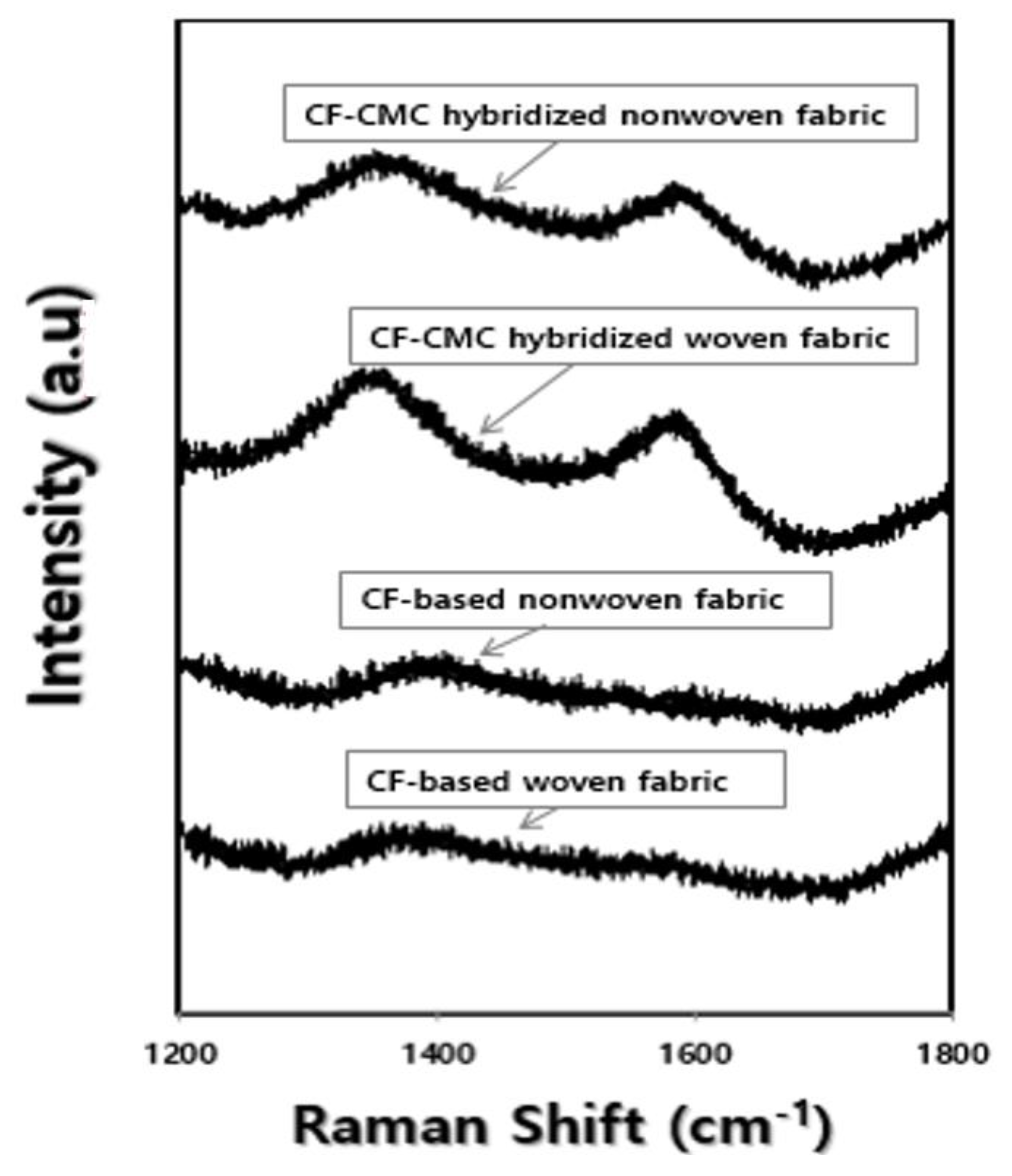
| Samples and Measuring Direction | G-Band Peak-Top (cm−1) | D-Band Peak-Top (cm−1) | ID/IG |
|---|---|---|---|
| After CF-CMC hybrid formation reaction of nonwoven fabric | 1586.6 | 1356.2 | 0.9922 |
| After CF-CMC hybrid formation reaction of woven fabric | 1594.0 | 1337.0 | 1.0071 |
| Various Carbon-Based Materials | Density (g/cm3) | Thickness (mm) | Conductivity (S/m) | Operating Frequency (GHz) | EMI SE (dB) | Refs. |
|---|---|---|---|---|---|---|
| *PMMA/graphene | 0.79 | 2.40 | 3.11 | 8–12 | 13–19 | [22] |
| *PS/graphene | 0.27 | 2.50 | 2.20 × 10⁻¹ | 8.2–12.4 | 17–22 | [23] |
| *PDMS/graphene | 0.06 | 1.00 | 2.00 × 10² | 8–12 | 18–40 | [9] |
| *PEI/graphene | 0.29 | 2.30 | 2.20 × 10⁻⁵ | 18–23 | [24] | |
| *PI/graphene | 0.28 | 0.80 | 8.00 × 10⁻¹ | 17–21 | [25] | |
| Graphene-foam | 0.06 | 0.30 | 3.10 × 10² | 8.2–12.5 | 23–27 | [26] |
| Multilayer-graphene paper | 1.09 | 0.50 × 10⁻¹ | 1.40 × 10⁵ | 8.2–12.4 | 62.5–74.8 | [27] |
| Iodine-doped *LG paper | – | 0.12 × 10⁻¹ | 1.05 × 10⁵ | 8.2–12.5 | 50–55 | [28] |
| *CNF-GN | 0.08–0.10 | 0.22–0.27 | 8.00 × 10² | 8.2−12.4 | 26-28 | [7] |
| Graphene aerogel/carbon texture | 0.07 | 3.00 | – | 8–12.5 | 36–37 | [29] |
| Fluorocarbon polymer/MWCNT | 1.70 | 3.80 | – | 8.2–12.4 | 46–52 | [30] |
| Fluorocarbon polymer/MWCNT foam | 1.20 | 3.80 | – | 42–45 | ||
| Nickel, Silver (Ni/Ag) plated nylon fabric. | – | 0.10 | 3.33 × 10² | 0.03–10 | 60 | [31] |
| Nickel, Copper, Silver (Ni/Cu/Ag) plated Nylon fabric | – | 0.12 | 8.89 × 10³ | 95 | ||
| Nonwoven fabric | 0.06 | 2.12 ± 0.22 | (2.40 ± 0.23) × 103 | 8–12 | 58–70 | This work |
| CF-CMC hybridized nonwoven fabric | 0.29 | 4.35 ± 0.11 | (1.39 ± 0.03) × 102 | 62–98 | ||
| Woven fabric | 0.44 | 0.56 ± 0.04 | Transverse: (0.82 ± 0.14) × 101 | 5–8 | ||
| Parallel: (3.23 ± 0.02) × 101 | ||||||
| CF-CMC hybridized woven fabric | 0.59 | 2.77 ± 0.34 | Transverse: (1.82 ± 0.20) × 102 | 27–30 | ||
| Parallel: (2.11 ± 0.25) × 102 |
© 2018 by the authors. Licensee MDPI, Basel, Switzerland. This article is an open access article distributed under the terms and conditions of the Creative Commons Attribution (CC BY) license (http://creativecommons.org/licenses/by/4.0/).
Share and Cite
Kim, H.-J.; Kim, S.-H.; Park, S. Effects of the Carbon Fiber-Carbon Microcoil Hybrid Formation on the Effectiveness of Electromagnetic Wave Shielding on Carbon Fibers-Based Fabrics. Materials 2018, 11, 2344. https://doi.org/10.3390/ma11122344
Kim H-J, Kim S-H, Park S. Effects of the Carbon Fiber-Carbon Microcoil Hybrid Formation on the Effectiveness of Electromagnetic Wave Shielding on Carbon Fibers-Based Fabrics. Materials. 2018; 11(12):2344. https://doi.org/10.3390/ma11122344
Chicago/Turabian StyleKim, Hyun-Ji, Sung-Hoon Kim, and Sangmoon Park. 2018. "Effects of the Carbon Fiber-Carbon Microcoil Hybrid Formation on the Effectiveness of Electromagnetic Wave Shielding on Carbon Fibers-Based Fabrics" Materials 11, no. 12: 2344. https://doi.org/10.3390/ma11122344