Electrical/Mechanical Monitoring of Shape Memory Alloy Reinforcing Fibers Obtained by Pullout Tests in SMA/Cement Composite Materials

Abstract
:1. Introduction
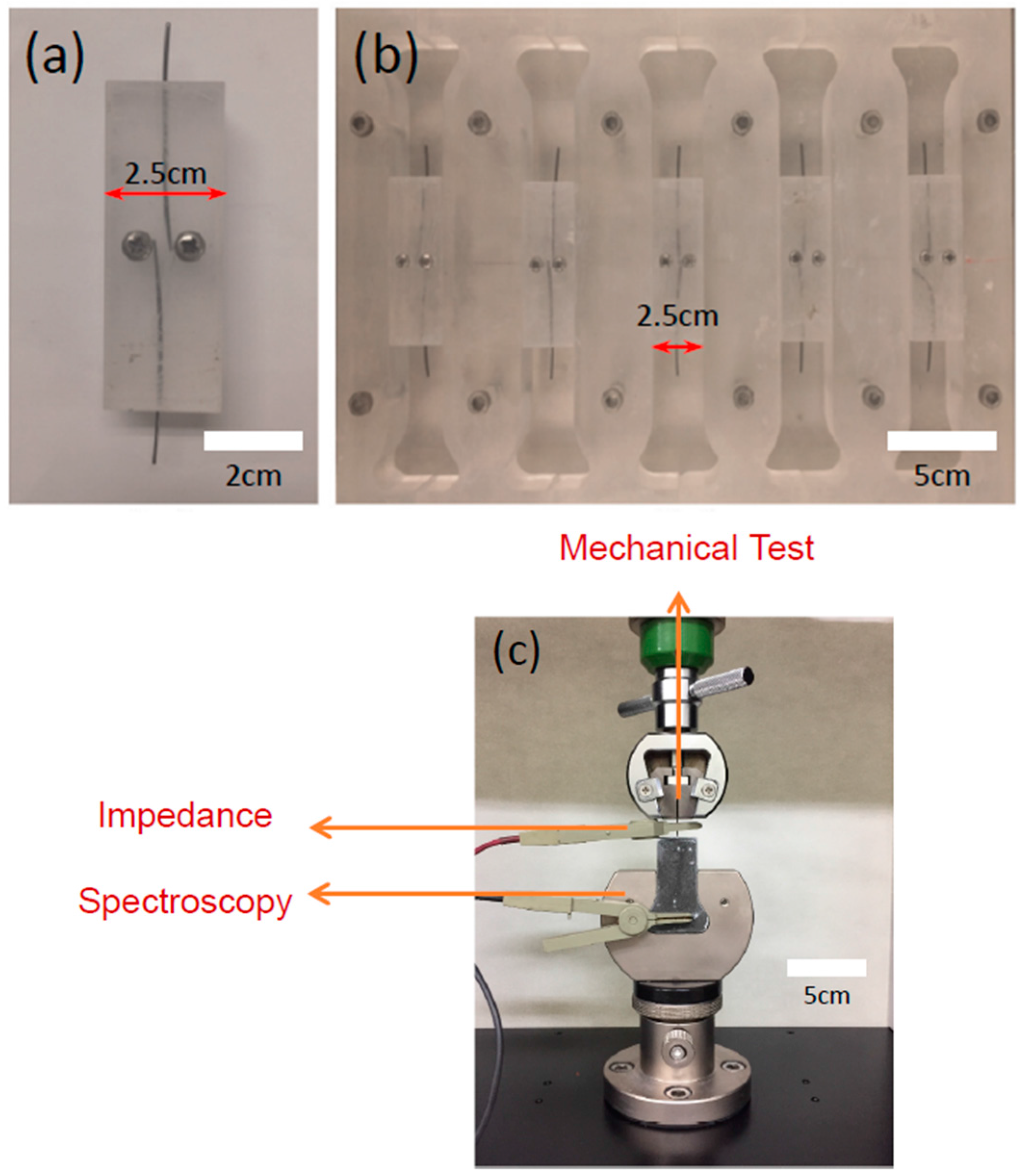
2. Experimental
3. Results & Discussion
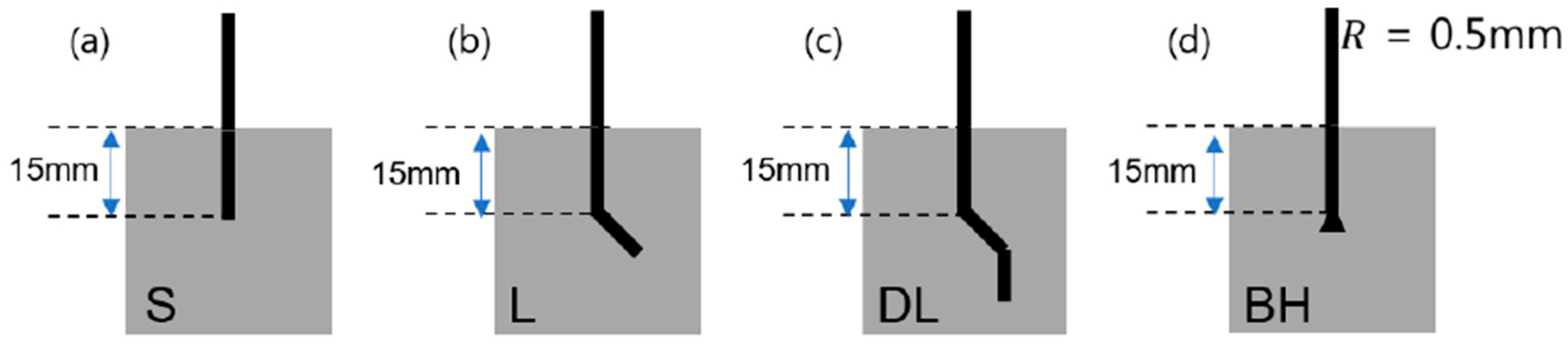
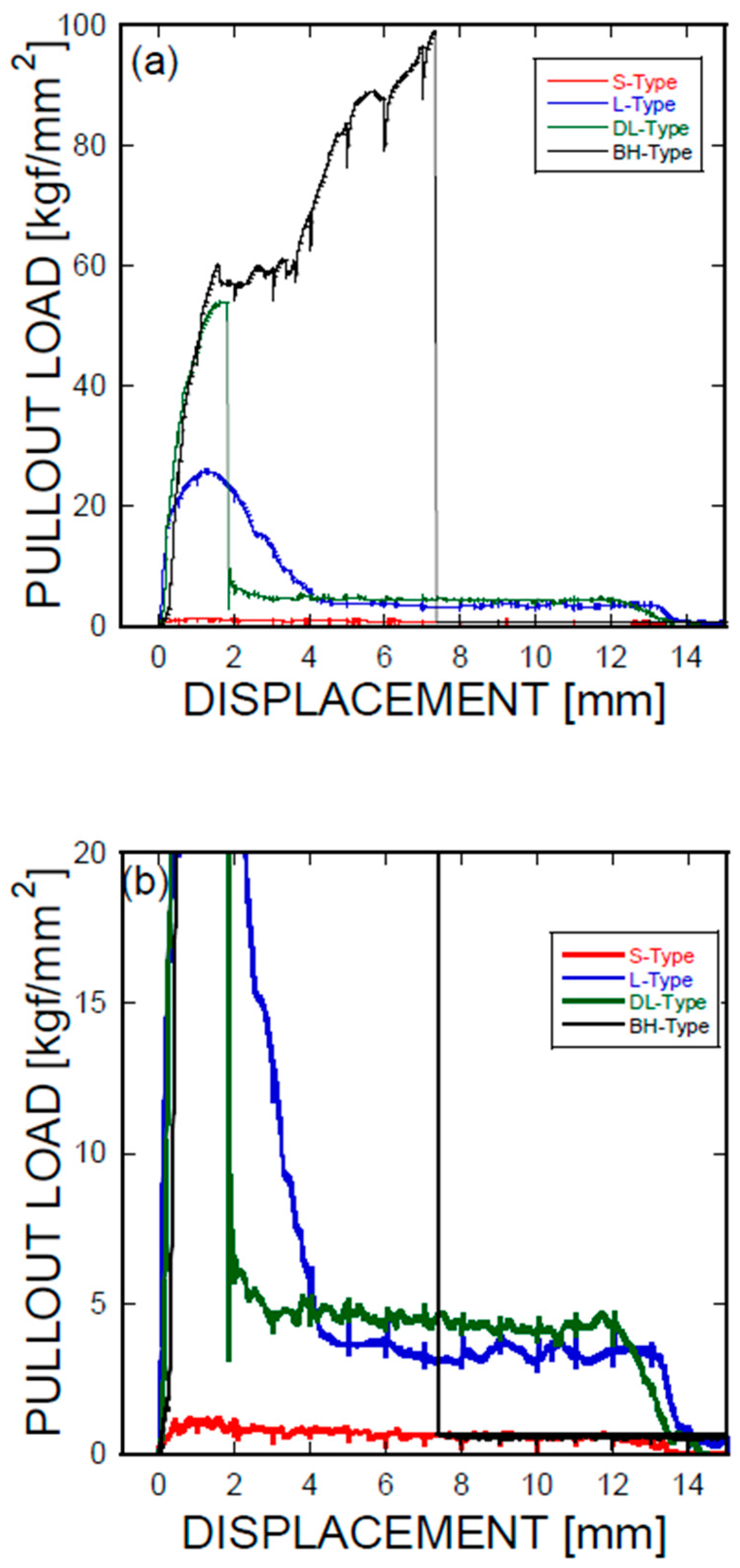
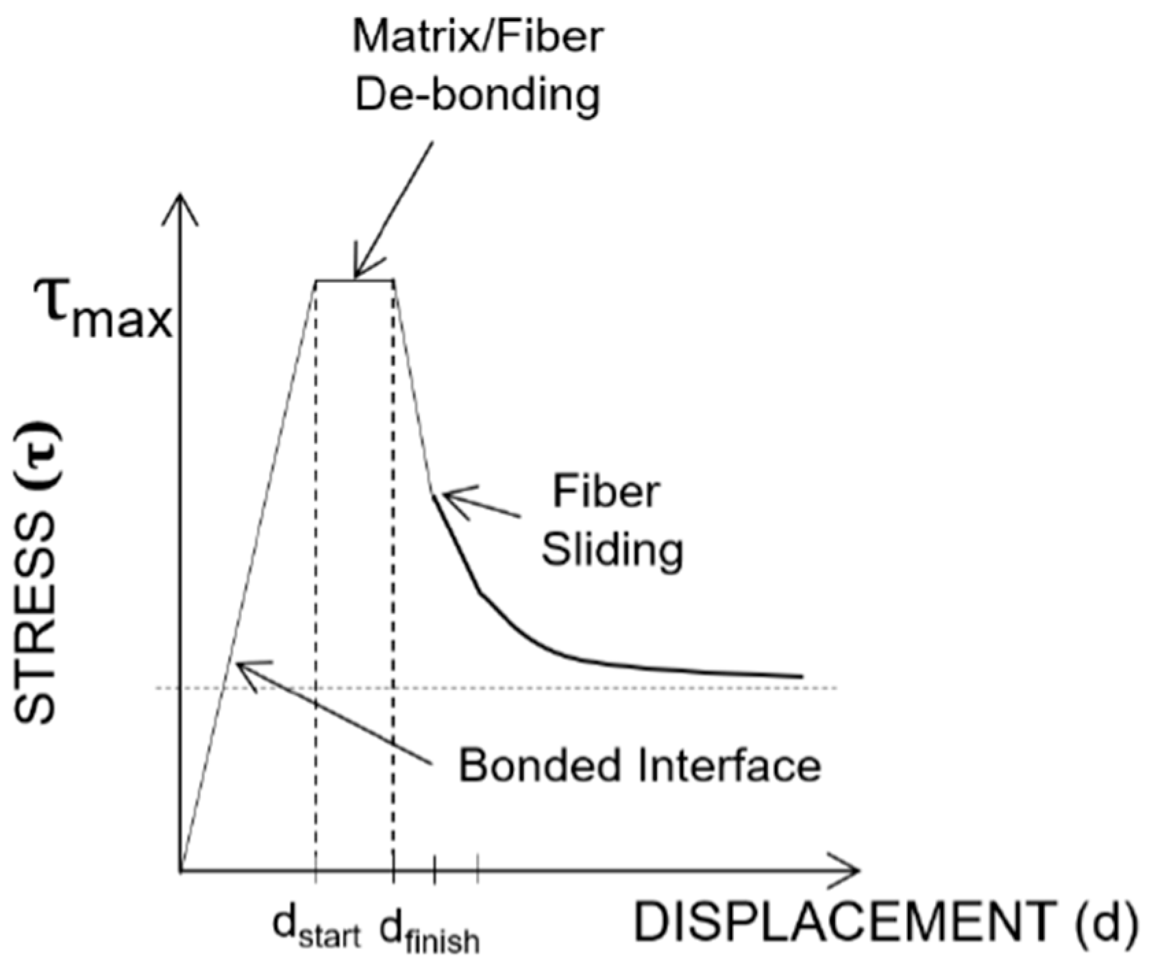
3.1. Mechanical Characterization of the NiTi SMA Fibers Embedded into the Cement Mortar
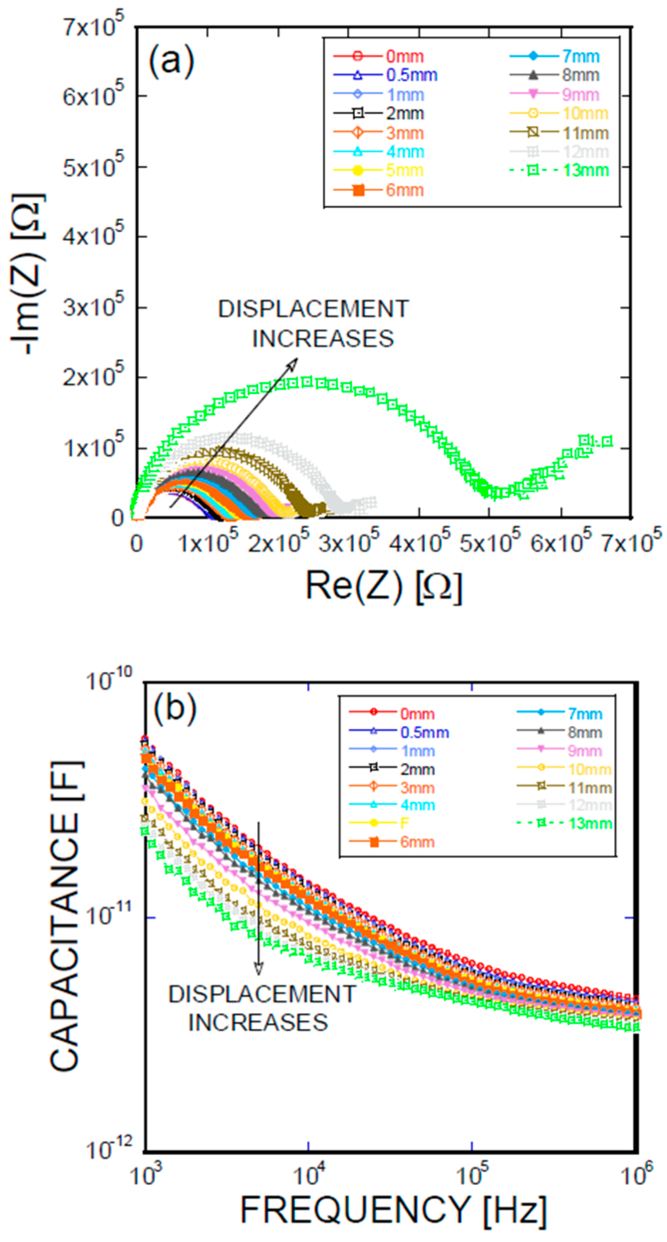
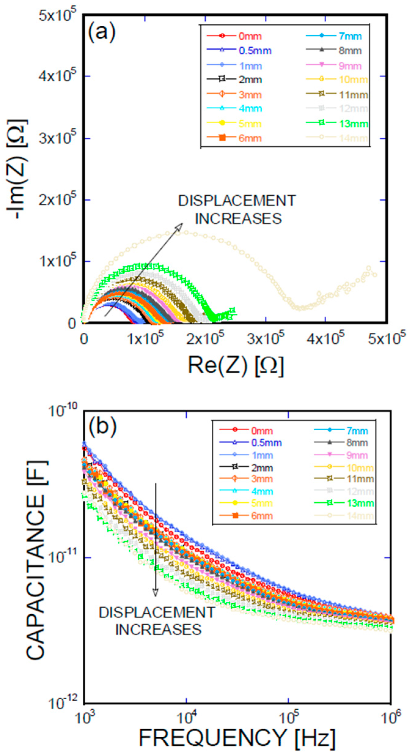
3.2. Impedance-Based Characterization of the NiTi SMA Fibers Embedded in the Cement
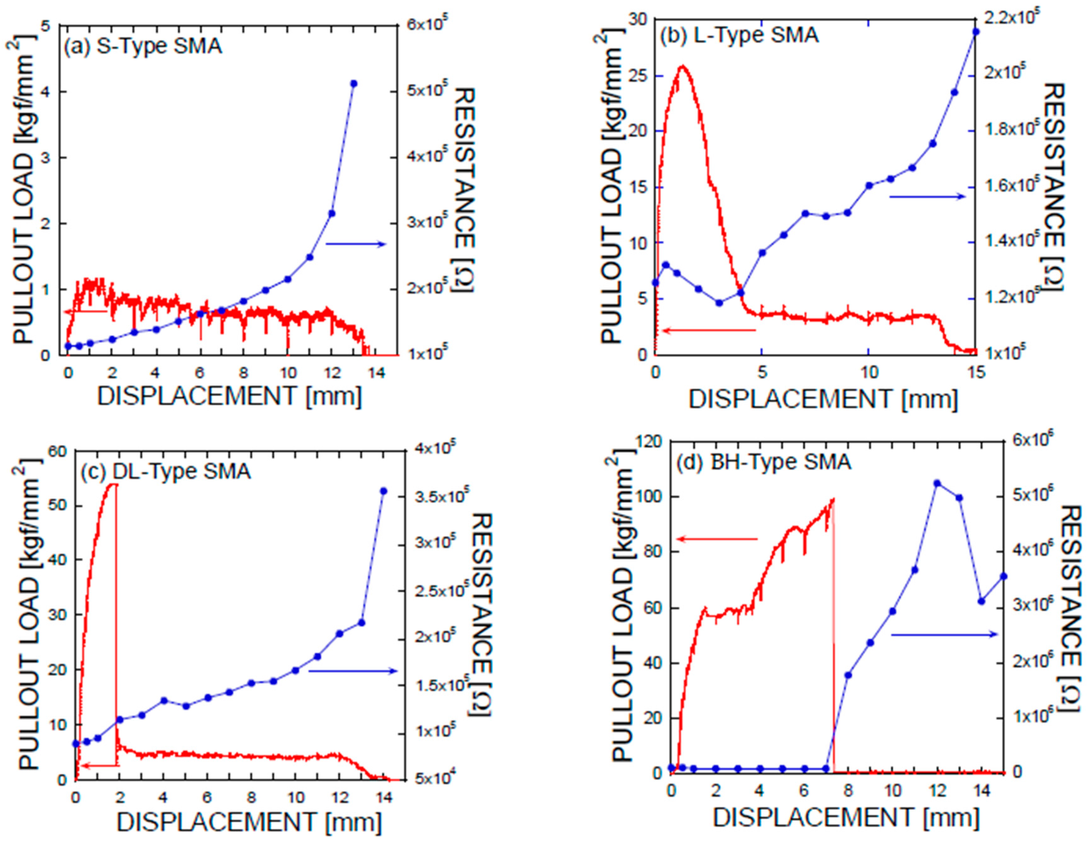
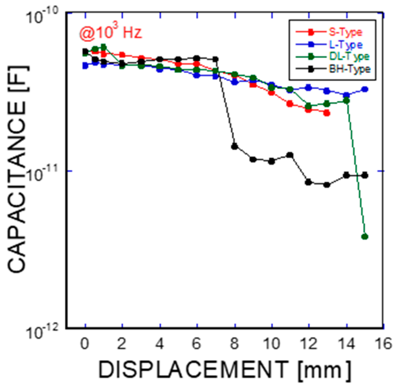
3.3. Relationship between the Mechanical and Electrical Characterizations of the Ni/Ti SMA Fibers Embedded in the Cement
4. Conclusions
Acknowledgments
Author Contributions
Conflicts of Interest
References
- DesRoches, R.; McCormick, J.; Delement, N. Cyclic properties of superelastic shape memory alloy wires and bars. J. Struct. Eng. 2004, 130, 38–46. [Google Scholar] [CrossRef]
- Boyd, J.G.; Lagoudas, D.C. A thermodynamical constitutive model for shape memory materials. Part I. The monolithic shape memory alloy. Int. J. Plast. 1996, 12, 805–842. [Google Scholar] [CrossRef]
- Pozzi, M.; Airoldi, G. The electrical transport properties of shape memory alloys. Mater. Sci. Eng. A 1999, 273–275, 300–304. [Google Scholar] [CrossRef]
- Eggeler, G.; Hornbogen, E.; Yawny, A.; Heckmann, A.; Wagner, M. Structural and functional fatigue of NiTi shape memory alloys. Mater. Sci. Eng. A 2004, 378, 24–33. [Google Scholar] [CrossRef]
- Lv, J.; Liang, T.; Wang, C.; Dong, L. Surface corrosion enhancement of passive films on NiTi shape memory alloy in different solutions. Mater. Sci. Eng. C 2016, 63, 192–197. [Google Scholar] [CrossRef] [PubMed]
- Janke, L.; Czaderski, C.; Metavalli, M.; Ruth, J. Application of shape memory alloys in civil engineering structures—Overview, limits, and new ideas. Mater. Struct. 2005, 38, 578–592. [Google Scholar]
- Saiidi, M.S.; Wang, H. Exploratory study of seismic response of concrete columns with shape memory alloys reinforcement. ACI Struct. J. 2006, 103, 436–442. [Google Scholar]
- Song, P.S.; Hwang, S. Mechanical properties of high-strength steel fiber-reinforced concrete. Constr. Build. Mater. 2004, 18, 669–673. [Google Scholar] [CrossRef]
- Chen, P.W.; Chung, D.D.L. Carbon fiber reinforced concrete for smart structures capable of non-destructive flaw detection. Smart Mater. Struct. 1993, 2, 22–30. [Google Scholar] [CrossRef]
- Saafi, M.; Houtanji, A.; Li, Z. Behavior of concrete columns confined with fiber reinforced polymer tubes. ACI Mater. J. 1999, 96, 500–509. [Google Scholar]
- Gur, S.; Mishra, S.K.; Frantziskonis, G.N. Thermo-mechanical strain rate–dependent behavior of shape memory alloys as vibration dampers and comparison to conventional dampers. J. Intell. Mater. Syst. Struct. 2016, 27, 1250–1264. [Google Scholar] [CrossRef]
- McCarter, W.J.; Garvin, S. Dependence of electrical impedance of cement-based materials on their moisture condition. J. Phys. D Appl. Phys. 1989, 22, 1773–1776. [Google Scholar] [CrossRef]
- Christensen, B.J.; Coverdale, R.T.; Olson, R.A.; Ford, S.J.; Garboczi, E.J.; Jennings, H.M.; Mason, T.O. Impedance spectroscopy of hydrating cement-based materials: Measurement, interpretation, and application. J. Am. Ceram. Soc. 1994, 77, 2789–2804. [Google Scholar] [CrossRef]
- Torrents, J.M.; Mason, T.O.; Peled, A.; Shah, S.P.; Garboczi, E.J. Analysis of the impedance spectra of short conductive fiber-reinforced composites. J. Mater. Sci. 2001, 36, 4003–4012. [Google Scholar] [CrossRef]
- Torrents, J.M.; Easley, T.C.; Faber, K.T.; Mason, T.O.; Shah, S.P. Evolution of impedance spectra during debonding and pullout of single steel fibers from cement. J. Am. Ceram. Soc. 2001, 84, 740–746. [Google Scholar] [CrossRef]
- Barsoukov, E.; Macdonald, J.R. Impedance Spectroscopy: Theory, Experiment, and Applications, 2nd ed.; John Wiley and Sons: New York, NY, USA, 2005. [Google Scholar]
- Fu, X.; Chung, D.D.L. Bond strength and contact electrical resistivity between cement and stainless steel fiber: Their correlation and dependence on fiber surface treatment and curing age. ACI Mater. J. 1997, 94, 203–208. [Google Scholar]
- Zhan, Y.; Meschke, G. A Multiscale oriented concept for the analyses of steel fiber reinforced concrete materials and structures. In Proceedings of the VIII International Conference on Fracture Mechanics of Concrete and Concrete Structures, FraMCoS-8, Toledo, Spain, 10–14 March 2013; Van Mier, J.G.M., Ruiz, G., Andrade, C., Yu, R.C., Zhang, X.X., Eds.; Aedificatio Publishers: Freiburg, Germany, 2013. [Google Scholar]
- Kim, J.J.; Kim, D.J.; Kang, S.T.; Lee, J.H. Influence of sand to coarse aggregate ratio on the interfacial strength of steel fibers in concrete for nuclear power plant. Nucl. Eng. Des. 2012, 252, 1–10. [Google Scholar] [CrossRef]
- Choi, E.; Kim, D.; Lee, J.H.; Ryu, G.S. Monotonic and hysteric pullout behavior of superplastic SMA fibers with different anchorages. Compos. Part B Eng. 2017, 108, 232–242. [Google Scholar] [CrossRef]
- Kim, D.J.; Kim, H.A.; Chung, Y.S.; Choi, E. Pullout resistance of deformed shape memory alloy fibers embedded in cement mortar. J. Intell. Mater. Syst. Struct. 2016, 27, 249–260. [Google Scholar] [CrossRef]
- Stang, H. Significance of shrinkage-induced clamping pressure in fiber-matrix bonding in cementitious composite materials. Adv. Cem. Based Mater. 1996, 4, 106–115. [Google Scholar] [CrossRef]


| Displacement [mm] | S-Type | L-Type | DL-Type | BH-Type | ||||
|---|---|---|---|---|---|---|---|---|
| Load [kgf] | Resistance [Ω] | Load [kgf] | Resistance [Ω] | Load [kgf] | Resistance [Ω] | Load [kgf] | Resistance [Ω] | |
| 0 | 0.000 | 1.14 × 10⁵ | 0.000 | 1.26 × 10⁵ | 0.000 | 8.85 × 10⁴ | 0.000 | 1.14 × 10⁵ |
| 0.5 | 0.900 | 1.14 × 10⁵ | 32.159 | 1.32 × 10⁵ | 32.159 | 9.06 × 10⁴ | 25.604 | 1.10 × 10⁵ |
| 1 | 1.105 | 1.18 × 10⁵ | 46.015 | 1.29 × 10⁵ | 46.015 | 9.49 × 10⁴ | 46.851 | 1.07 × 10⁵ |
| 2 | 0.977 | 1.24 × 10⁵ | 6.067 | 1.24 × 10⁵ | 6.067 | 1.14 × 10⁵ | 57.005 | 1.05 × 10⁵ |
| 3 | 0.810 | 1.34 × 10⁵ | 4.473 | 1.19 × 10⁵ | 4.473 | 1.19 × 10⁵ | 59.434 | 1.08 × 10⁵ |
| 4 | 0.835 | 1.39 × 10⁵ | 4.961 | 1.22 × 10⁵ | 4.961 | 1.34 × 10⁵ | 68.650 | 1.06 × 10⁵ |
| 5 | 0.746 | 1.51 × 10⁵ | 4.781 | 1.37 × 10⁵ | 4.781 | 1.29 × 10⁵ | 83.650 | 1.02 × 10⁵ |
| 6 | 0.630 | 1.62 × 10⁵ | 4.460 | 1.43 × 10⁵ | 4.460 | 1.38 × 10⁵ | 87.699 | 9.74 × 10⁴ |
| 7 | 0.630 | 1.69 × 10⁵ | 4.563 | 1.51 × 10⁵ | 4.563 | 1.43 × 10⁵ | 96.491 | 9.67 × 10⁴ |
| 8 | 0.514 | 1.83 × 10⁵ | 4.344 | 1.50 × 10⁵ | 4.344 | 1.53 × 10⁵ | 0.566 | 1.78 × 10⁶ |
| 9 | 0.643 | 1.99 × 10⁵ | 4.242 | 1.51 × 10⁵ | 4.242 | 1.55 × 10⁵ | 0.527 | 2.37 × 10⁶ |
| 10 | 0.476 | 2.15 × 10⁵ | 4.139 | 1.61 × 10⁵ | 4.139 | 1.67 × 10⁵ | 0.604 | 2.93 × 10⁶ |
| 11 | 0.540 | 2.48 × 10⁵ | 4.267 | 1.63 × 10⁵ | 4.267 | 1.82 × 10⁵ | 0.643 | 3.68 × 10⁶ |
| 12 | 0.656 | 3.15 × 10⁵ | 4.216 | 1.67 × 10⁵ | 4.216 | 2.05 × 10⁵ | 0.566 | 5.25 × 10⁶ |
| 13 | 0.386 | 5.12 × 10⁵ | 2.237 | 1.76 × 10⁵ | 2.237 | 2.18 × 10⁵ | 0.604 | 4.99 × 10⁶ |
| 14 | 0.000 | - | 0.540 | 1.94 × 10⁵ | 0.540 | 3.57 × 10⁵ | 0.566 | 3.12 × 10⁶ |
| 15 | 0.000 | - | −0.167 | 2.16 × 10⁵ | −0.167 | - | 0.591 | 3.57 × 10⁶ |
| Parameter | S-Type | L-Type | DL-Type | BH-Type |
|---|---|---|---|---|
| dstart | 0.68 | 1.19 | 1.56 | 1.54 or 5.26 |
| dfinish | 1.59 | 1.35 | 1.82 | 3.63 or 6.00 |
| τmax | 1.157 | 25.810 | 53.869 | 60.375 or 88.217 |
© 2018 by the authors. Licensee MDPI, Basel, Switzerland. This article is an open access article distributed under the terms and conditions of the Creative Commons Attribution (CC BY) license (http://creativecommons.org/licenses/by/4.0/).
Share and Cite
Kim, E.-H.; Lee, H.; Kim, J.-H.; Bae, S.-M.; Hwang, H.; Yang, H.; Choi, E.; Hwang, J.-H. Electrical/Mechanical Monitoring of Shape Memory Alloy Reinforcing Fibers Obtained by Pullout Tests in SMA/Cement Composite Materials. Materials 2018, 11, 315. https://doi.org/10.3390/ma11020315
Kim E-H, Lee H, Kim J-H, Bae S-M, Hwang H, Yang H, Choi E, Hwang J-H. Electrical/Mechanical Monitoring of Shape Memory Alloy Reinforcing Fibers Obtained by Pullout Tests in SMA/Cement Composite Materials. Materials. 2018; 11(2):315. https://doi.org/10.3390/ma11020315
Chicago/Turabian StyleKim, Eui-Hyun, Hyunbae Lee, Jae-Hwan Kim, Seung-Muk Bae, Heesu Hwang, Heesun Yang, Eunsoo Choi, and Jin-Ha Hwang. 2018. "Electrical/Mechanical Monitoring of Shape Memory Alloy Reinforcing Fibers Obtained by Pullout Tests in SMA/Cement Composite Materials" Materials 11, no. 2: 315. https://doi.org/10.3390/ma11020315