Influence of Inherent Surface and Internal Defects on Mechanical Properties of Additively Manufactured Ti6Al4V Alloy: Comparison between Selective Laser Melting and Electron Beam Melting

Abstract
:1. Introduction
2. Materials and Methods
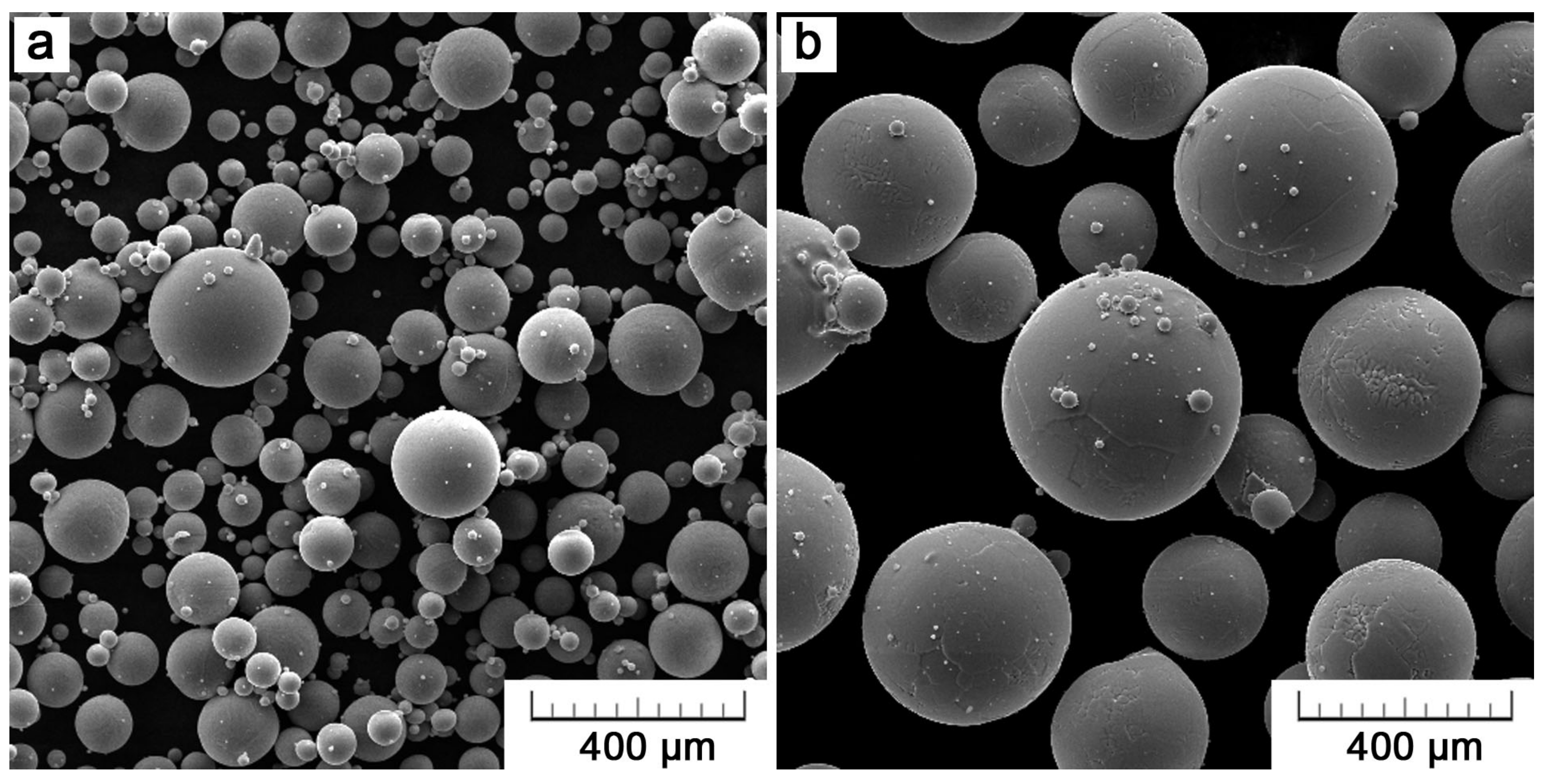
2.1. Materials
2.2. Surface and Microstructure Characterization
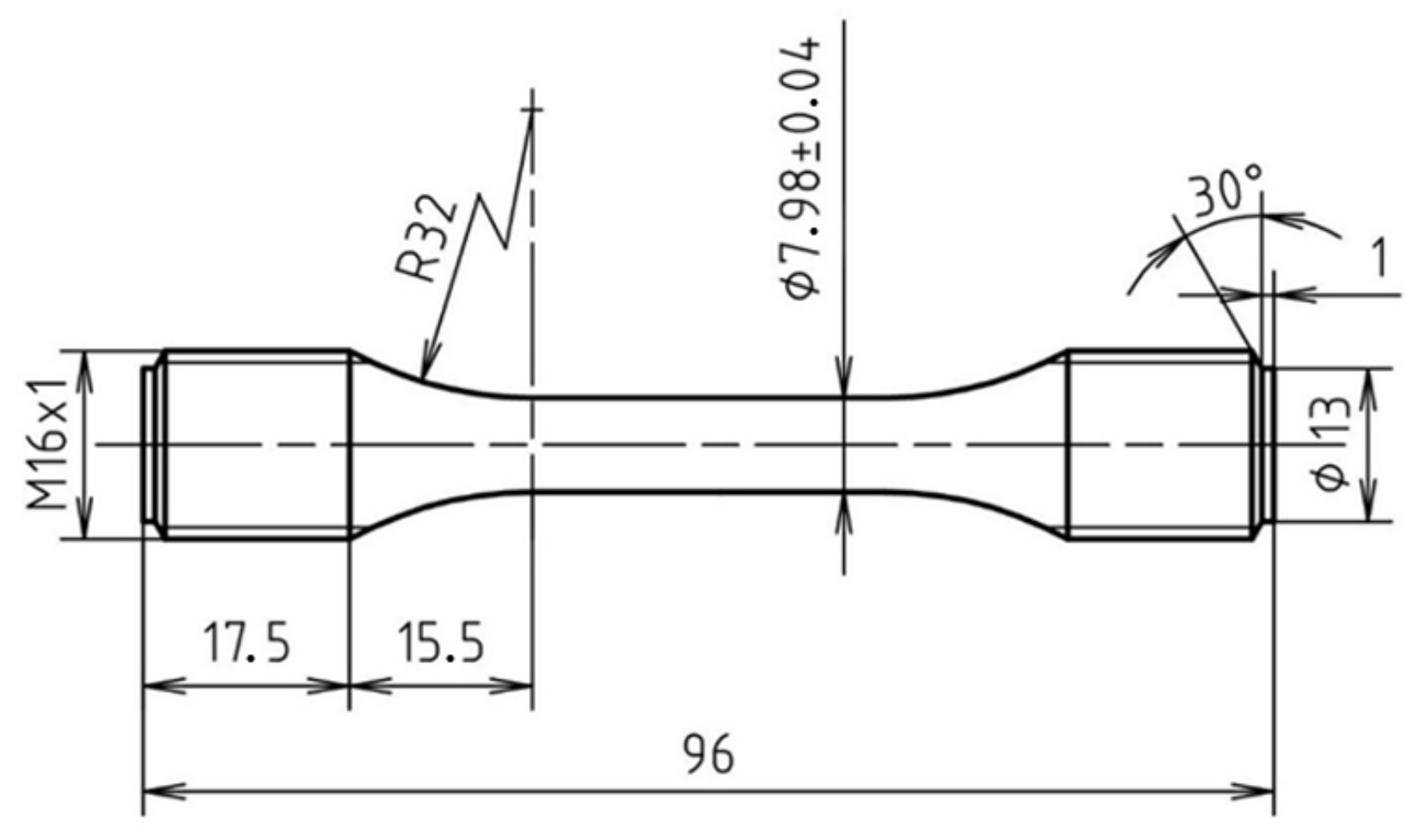
2.3. Evaluation of Mechanical Properties
3. Results
3.1. Additively-Manufactured Ti6Al4V
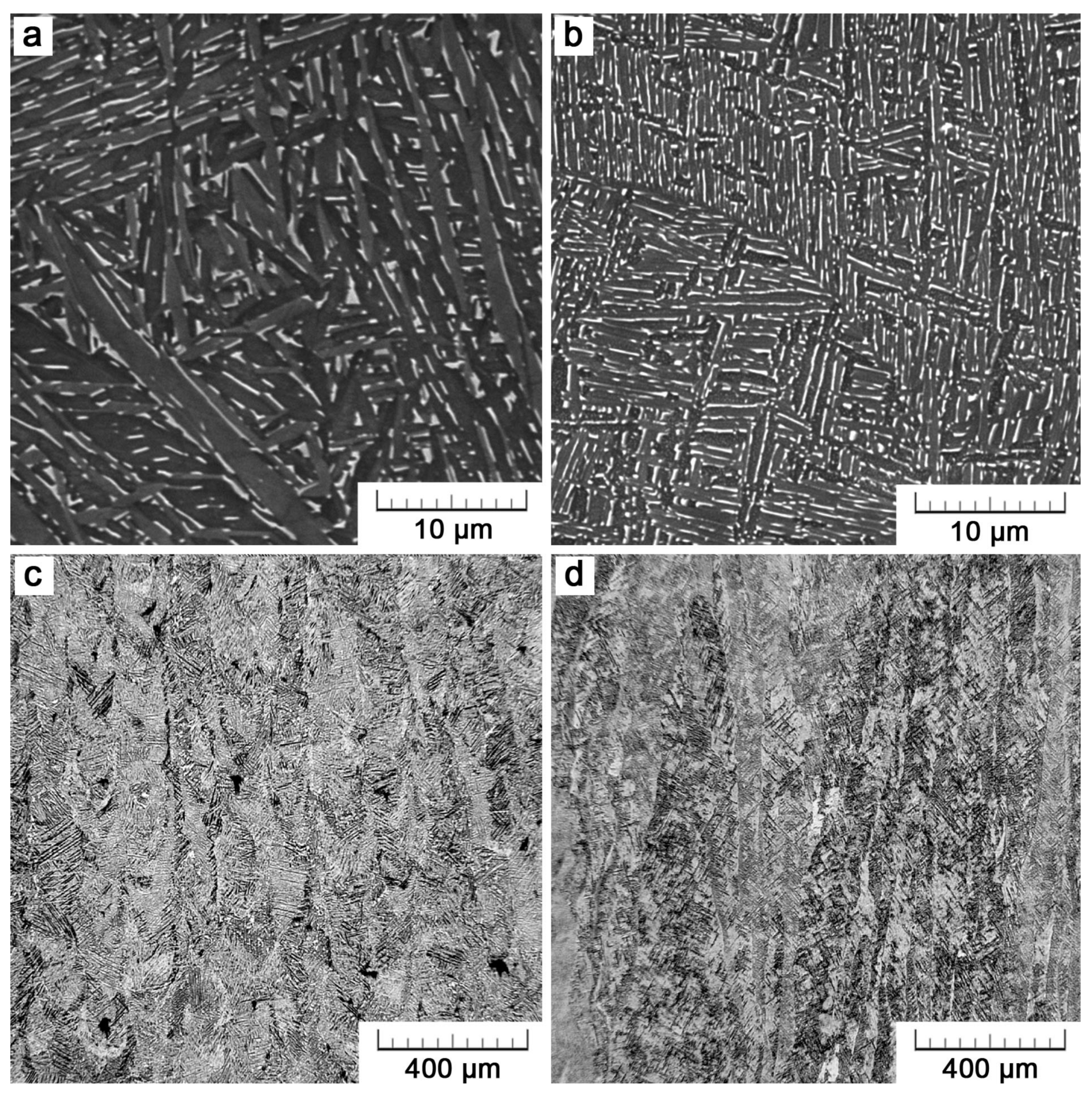
3.1.1. Microstructure
3.1.2. Surface
3.2. Mechanical Properties
3.2.1. Static Properties
3.2.2. Fatigue
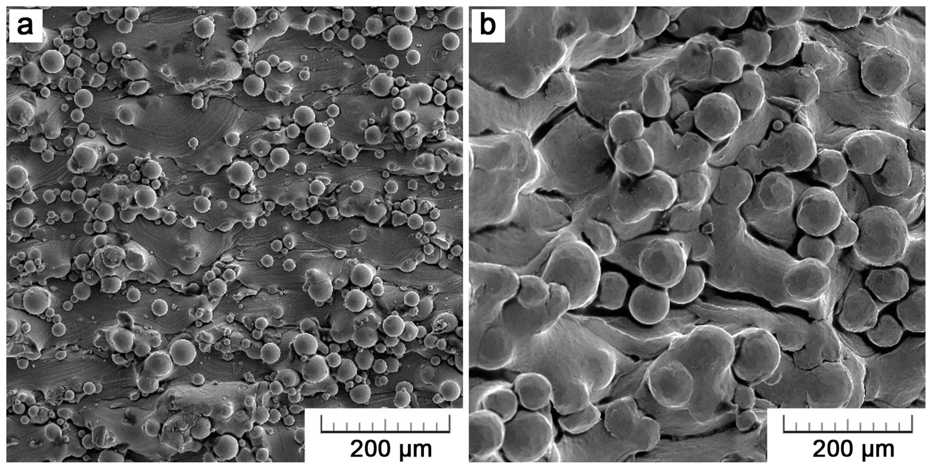
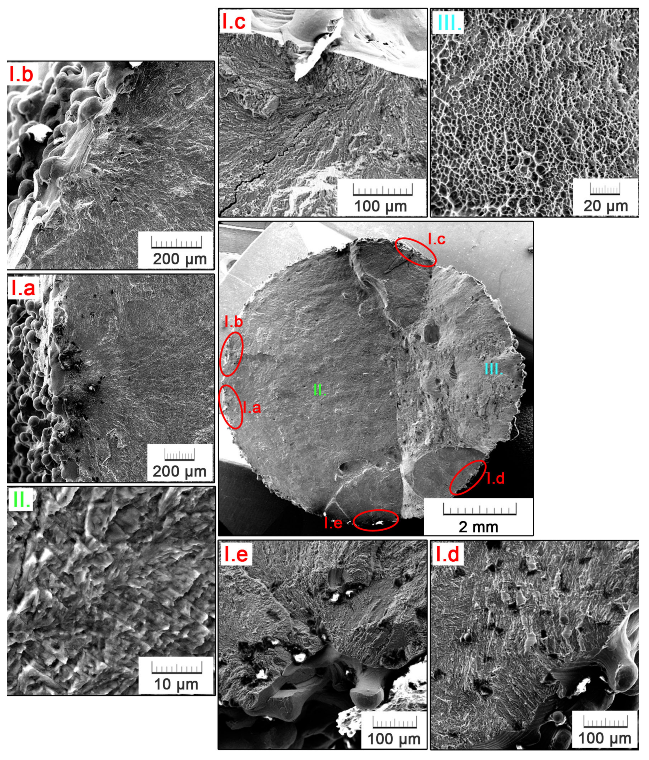
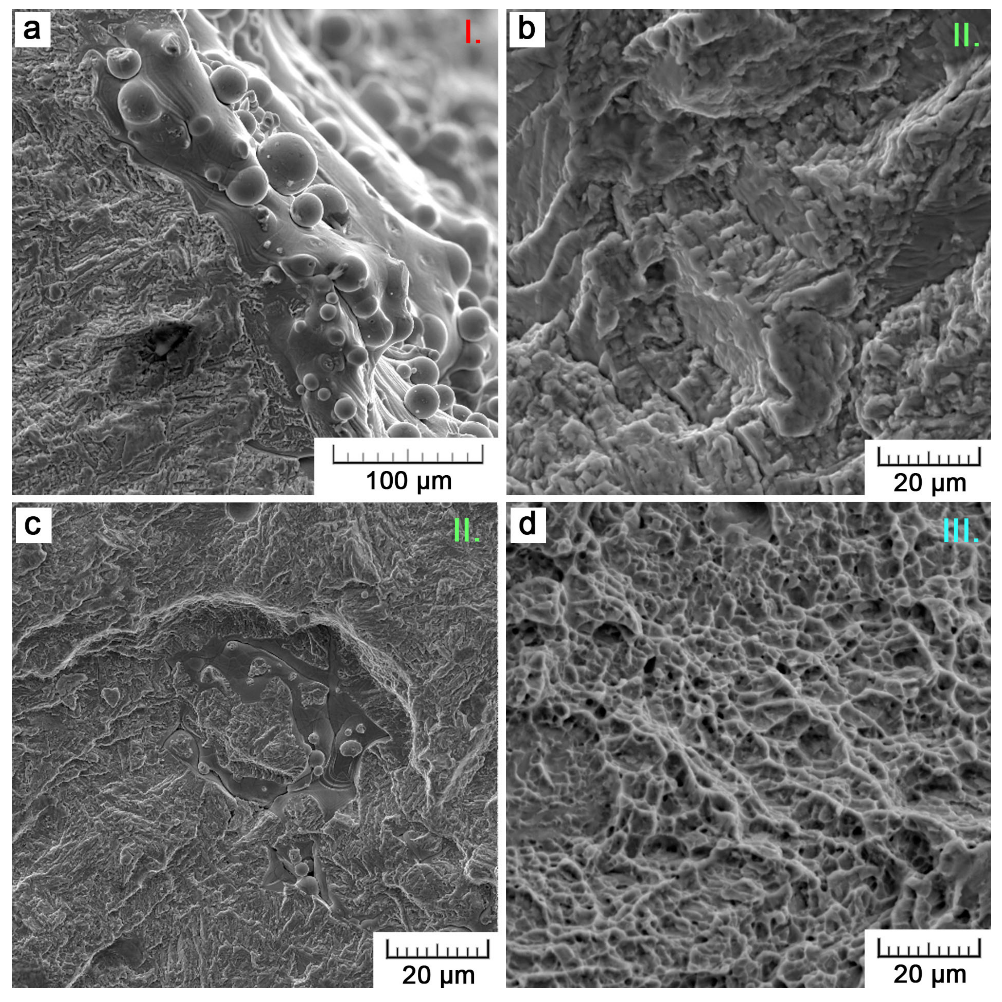
3.3. Fractography
4. Discussion
4.1. Microstructure
4.2. Mechanical Properties
4.2.1. Static Properties
4.2.2. Fatigue
5. Conclusions
- The metallographic analysis proved a very fine two-phase lamellar microstructure with a low amount of porosity (0.5% in maximum) for both SLM and EBM specimens.
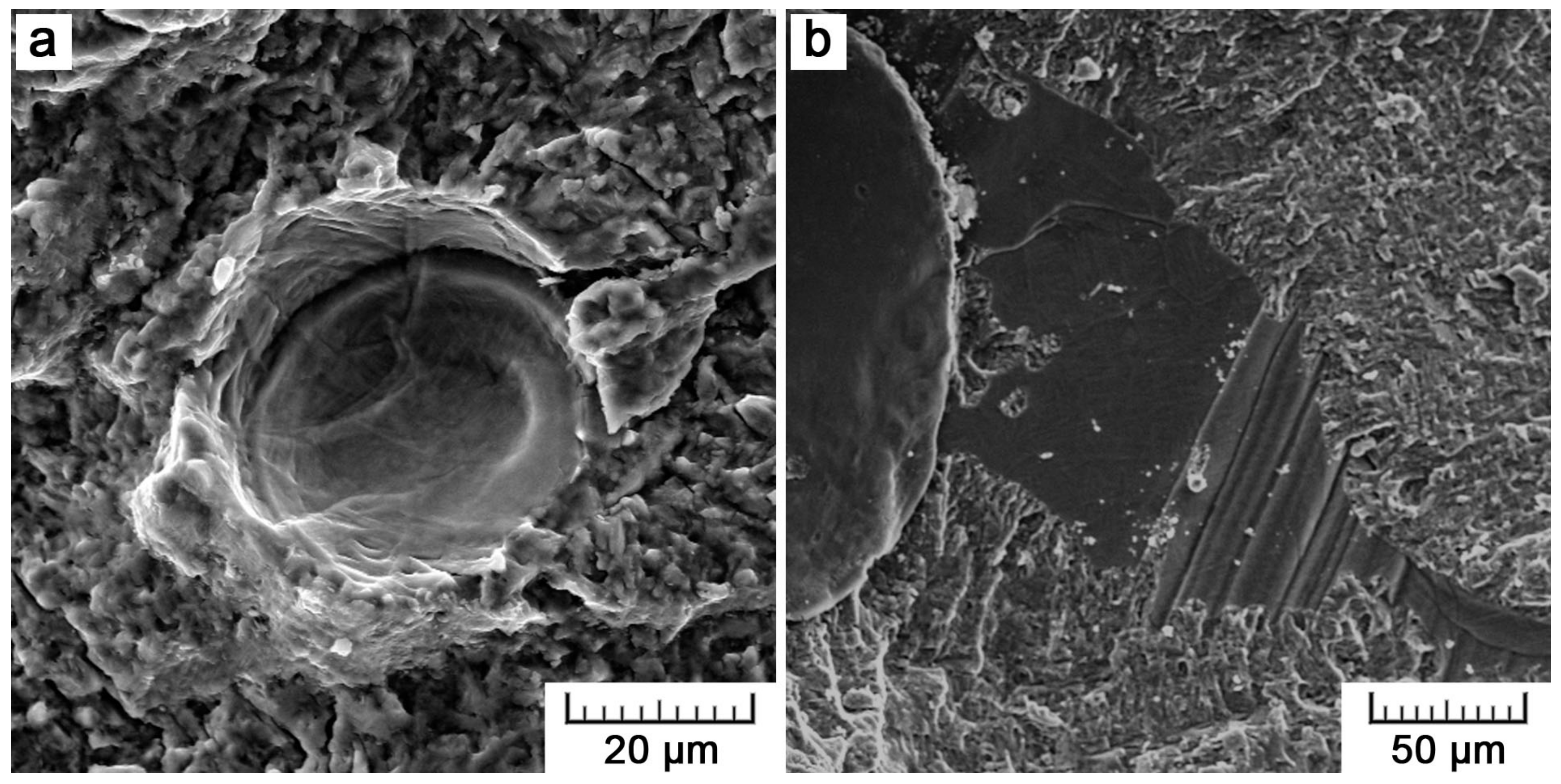
- Internal defects were of a different origin. In SLM, insufficient melting defects prevailed, while spherical pores in EBM resulted from gas entrapment.
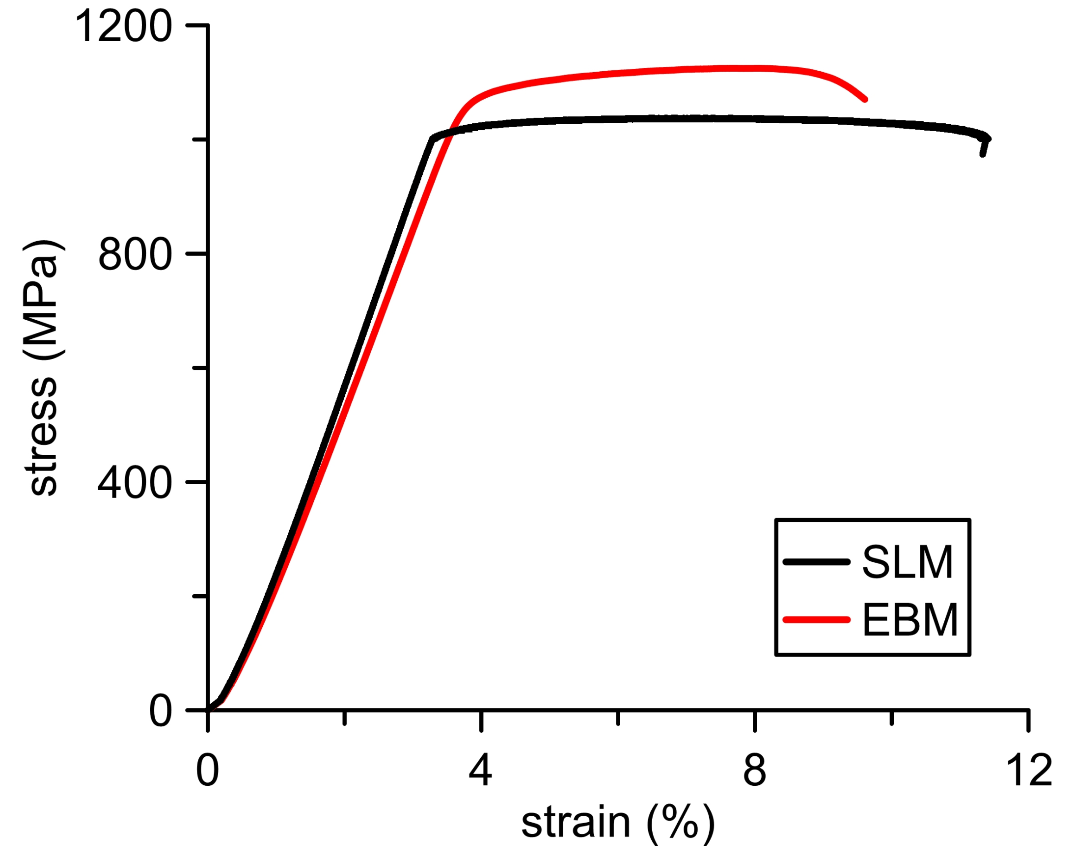
- Regarding comparable microstructures and relative densities, static properties in tension reached similar values.
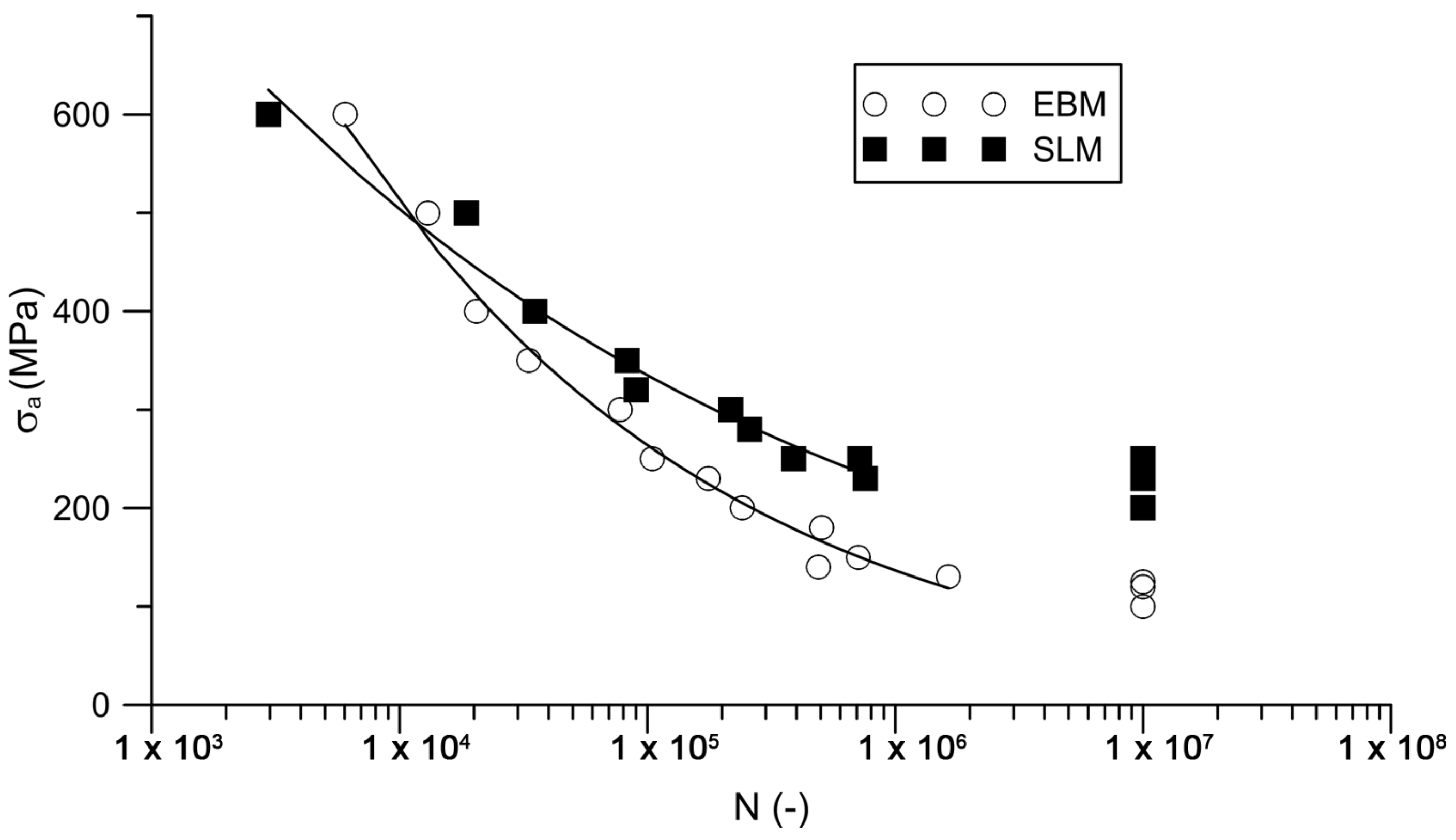
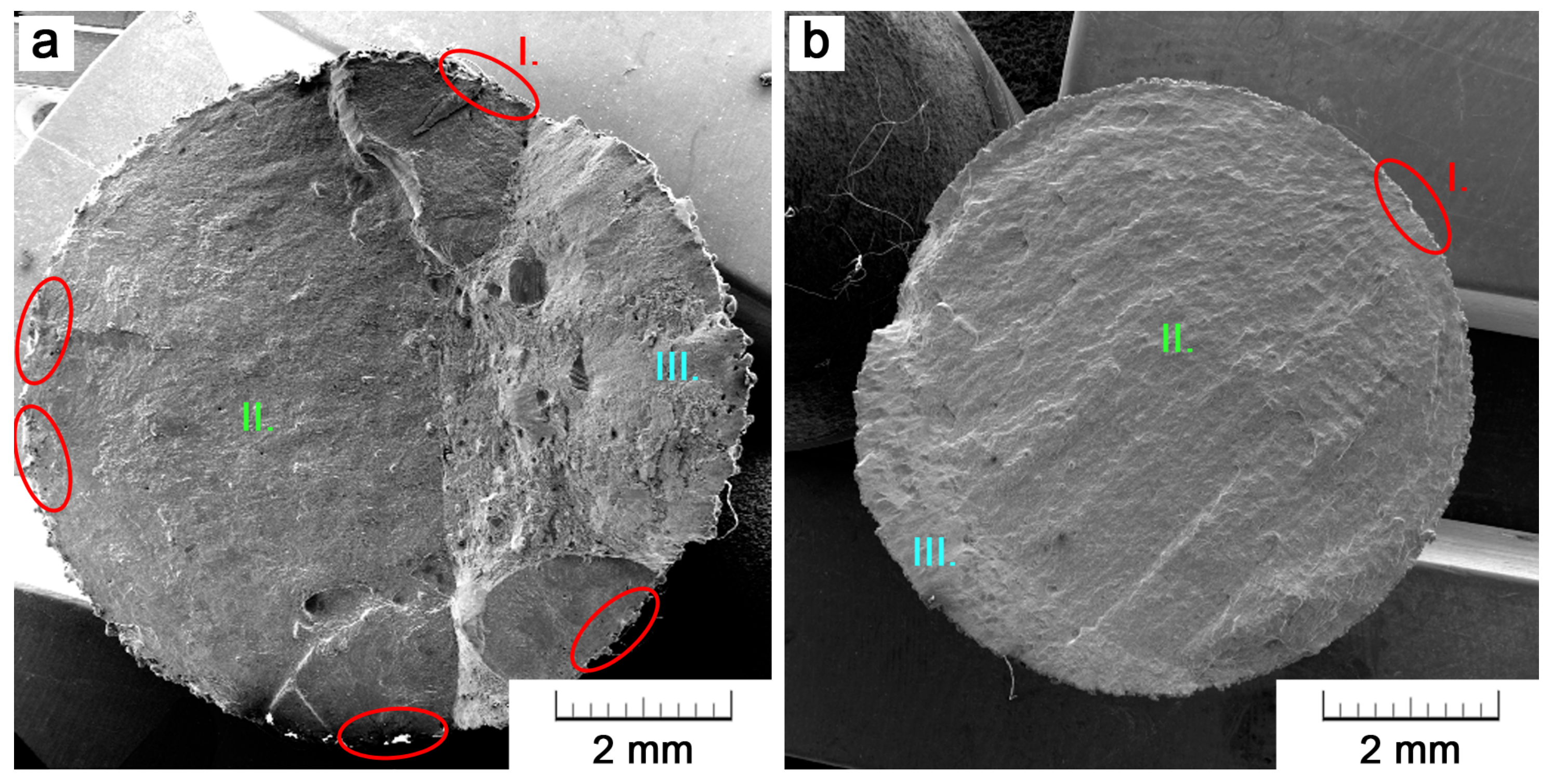
- On the contrary, a significant difference was registered in fatigue behavior. Due to a higher surface roughness and more harmful defects distributed across the whole section, fatigue strength reached 115 ± 13 MPa for EBM when compared to 220 ± 24 MPa for SLM.
- From the fatigue point of view, in the current state of art, SLM seems to be a better choice for the fabrication of porous structures in which surface effect cannot be eliminated.
Acknowledgments
Author Contributions
Conflicts of Interest
References
- Banerjee, D.; Williams, J.C. Perspectives on titanium science and technology. Acta Mater. 2013, 61, 844–879. [Google Scholar] [CrossRef]
- Edwards, P.; Ramulu, M. Fatigue performance evaluation of selective laser melted Ti–6Al–4V. Mater. Sci. Eng. A 2014, 598, 327–337. [Google Scholar] [CrossRef]
- Murr, L.E. Frontiers of 3D printing/additive manufacturing: from human organs to aircraft fabrication. J. Mater. Sci. Technol. 2016, 32, 987–995. [Google Scholar] [CrossRef]
- Levy, G.N. The role and future of the laser technology in the additive manufacturing environment. Phys. Procedia 2010, 5, 65–80. [Google Scholar] [CrossRef]
- Wong, K.V.; Hernandez, A. A review of additive manufacturing. ISRN Mech. Eng. 2012, 2012, 208760. [Google Scholar] [CrossRef]
- Calleja, A.; Tabernero, I.; Fernández, A.; Celaya, A.; Lamikiz, A.; López de Lacalle, L.N. Improvement of strategies and parameters for multi-axis laser cladding operations. Opt. Lasers Eng. 2014, 56, 113–120. [Google Scholar] [CrossRef]
- Frazier, W.E. Metal additive manufacturing: A review. J. Mater. Eng. Perform. 2014, 23, 1917–1928. [Google Scholar] [CrossRef]
- Herzog, D.; Seyda, V.; Wycisk, E.; Emmelmann, C. Additive manufacturing of metals. Acta Mater. 2016, 117, 371–392. [Google Scholar] [CrossRef]
- Edwards, P.; O’Conner, A.; Ramulu, M. Electron beam additive manufacturing of titanium components: Properties and performance. J. Manuf. Sci. Eng. 2013, 135, 061016. [Google Scholar] [CrossRef]
- Murr, L.E.; Gaytan, S.M.; Ramirez, D.A.; Martinez, E.; Hernandez, J.; Amato, K.N.; Shindo, P.W.; Medina, F.R.; Wicker, R.B. Metal fabrication by additive manufacturing using laser and electron beam melting technologies. J. Mater. Sci. Technol. 2012, 28, 1–14. [Google Scholar] [CrossRef]
- Murr, L.E.; Martinez, E.; Amato, K.N.; Gaytan, S.M.; Hernandez, J.; Ramirez, D.A.; Shindo, P.W.; Medina, F.; Wicker, R.B. Fabrication of metal and alloy components by additive manufacturing: Examples of 3D materials science. J. Mater. Res. Technol. 2012, 1, 42–54. [Google Scholar] [CrossRef]
- Günther, J.; Krewerth, D.; Lippmann, T.; Leuders, S.; Tröster, T.; Weidner, A.; Biermann, H.; Niendorf, T. Fatigue life of additively manufactured Ti–6Al–4V in the very high cycle fatigue regime. Int. J. Fatigue 2017, 94, 236–245. [Google Scholar] [CrossRef]
- Hiemenz, J. Electron beam melting. Adv. Mater. Process. 2007, 165, 45–46. [Google Scholar]
- Rafi, H.; Karthik, N.; Gong, H.; Starr, T.L.; Stucker, B.E. Microstructures and mechanical properties of Ti6Al4V parts fabricated by selective laser melting and electron beam melting. J. Mater. Eng. Perform. 2013, 22, 3872–3883. [Google Scholar] [CrossRef]
- Chan, K.S.; Koike, M.; Mason, R.L.; Okabe, T. Fatigue life of titanium alloys fabricated by additive layer manufacturing techniques for dental implants. Metall. Mater. Trans. A 2013, 44, 1010–1022. [Google Scholar] [CrossRef]
- Zhao, X.; Li, S.; Zhang, M.; Liu, Y.; Sercombe, T.B.; Wang, S.; Hao, Y.; Yang, R.; Murr, L.E. Comparison of the microstructures and mechanical properties of Ti–6Al–4V fabricated by selective laser melting and electron beam melting. Mater. Des. 2016, 95, 21–31. [Google Scholar] [CrossRef]
- Gong, H.; Rafi, K.; Gu, H.; Janaki Ram, G.D.; Starr, T.; Stucker, B. Influence of defects on mechanical properties of Ti–6Al–4V components produced by selective laser melting and electron beam melting. Mater. Des. 2015, 86, 545–554. [Google Scholar] [CrossRef]
- Greitemeier, D.; Palm, F.; Syassen, F.; Melz, T. Fatigue performance of additive manufactured TiAl6V4 using electron and laser beam melting. Int. J. Fatigue 2017, 94, 211–217. [Google Scholar] [CrossRef]
- He, W.; Jia, W.; Liu, H.; Tang, H.; Kang, X.; Huang, Y. Research on preheating of titanium alloy powder in electron beam melting technology. Rare Met. Mater. Eng. 2011, 40, 2072–2075. [Google Scholar] [CrossRef]
- Yan, C.; Hao, L.; Hussein, A.; Young, P. Ti–6Al–4V triply periodic minimal surface structures for bone implants fabricated via selective laser melting. J. Mech. Behav. Biomed. Mater. 2015, 51, 61–73. [Google Scholar] [CrossRef] [PubMed] [Green Version]
- Gong, H.; Rafi, K.; Gu, H.; Starr, T.; Stucker, B. Analysis of defect generation in Ti–6Al–4V parts made using powder bed fusion additive manufacturing processes. Addit. Manuf. 2014, 1–4, 87–98. [Google Scholar] [CrossRef]
- Simonelli, M. Microstructure Evolution and Mechanical Properties of Selective Laser Melted Ti–6Al–4V. Ph.D. Thesis, School of Aeronautical, Automotive, Chemical and Materials Engineering, Loughborough University, Loughborough, UK, 2014. [Google Scholar]
- Fousová, M.; Vojtěch, D.; Kubásek, J.; Jablonská, E.; Fojt, J. Promising characteristics of gradient porosity Ti–6Al–4V alloy prepared by SLM process. J. Mech. Behav. Biomed. Mater. 2017, 69, 368–376. [Google Scholar] [CrossRef] [PubMed]
- Vilaro, T.; Colin, C.; Bartout, J.D. As-Fabricated and heat-treated microstructures of the Ti–6Al–4V alloy processed by Selective Laser Melting. Metall. Mater. Trans. A 2011, 42, 3190–3199. [Google Scholar] [CrossRef]
- Xu, W.; Brandt, M.; Sun, S.; Elambasseril, J.; Liu, Q.; Latham, K.; Xia, K.; Qian, M. Additive manufacturing of strong and ductile Ti–6Al–4V by Selective Laser Melting via in situ martensite decomposition. Acta Mater. 2015, 85, 74–84. [Google Scholar] [CrossRef]
- Ahmed, T.; Rack, H.J. Phase transformations during cooling in α + β titanium alloys. Mater. Sci. Eng. A 1998, 243, 206–211. [Google Scholar] [CrossRef]
- Sallica-Leva, E.; Caram, R.; Jardini, A.L.; Fogagnolo, J.B. Ductility improvement due to martensite α′ decomposition in porous Ti–6Al–4V parts produced by selective laser melting for orthopedic implants. J. Mech. Behav. Biomed. Mater. 2016, 54, 149–158. [Google Scholar] [CrossRef] [PubMed]
- Clemens, H.; Bartels, A.; Bystrzanowski, S.; Chladil, H.; Leitner, H.; Dehm, G.; Gerling, R.; Schimansky, F.P. Grain refinement in γ-TiAl-based alloys by solid state phase transformations. Intermetallics 2006, 14, 1380–1385. [Google Scholar] [CrossRef]
- Vrancken, B.; Thijs, L.; Kruth, J.-P.; Van Humbeeck, J. Heat treatment of Ti6Al4V produced by Selective Laser Melting: Microstructure and mechanical properties. J. Alloys Compd. 2012, 541, 177–185. [Google Scholar] [CrossRef]
- Fousová, M.; Vojtěch, D.; Kubásek, J. Titanium alloy Ti–6Al–4V prepared by Selective Laser Melting (SLM). Manuf. Technol. 2016, 16, 691–697. [Google Scholar]
- Hrabe, N.; Gnäupel-Herold, T.; Quinn, T. Fatigue properties of a titanium alloy (Ti–6Al–4V) fabricated via electron beam melting (EBM): Effects of internal defects and residual stress. Int. J. Fatigue 2017, 94, 202–210. [Google Scholar] [CrossRef]
- Zhai, Y.; Galarraga, H.; Lados, D.A. Microstructure, static properties, and fatigue crack growth mechanisms in Ti–6Al–4V fabricated by additive manufacturing: LENS and EBM. Eng. Fail. Anal. 2016, 69, 3–14. [Google Scholar] [CrossRef]
- Galarraga, H.; Warren, R.J.; Lados, D.A.; Dehoff, R.R.; Kirka, M.M. Fatigue crack growth mechanisms at the microstructure scale in as-fabricated and heat treated Ti–6Al–4V ELI manufactured by electron beam melting (EBM). Eng. Fract. Mech. 2017, 176, 263–280. [Google Scholar] [CrossRef]
- Murr, L.E.; Esquivel, E.V.; Quinones, S.A.; Gaytan, S.M.; Lopez, M.I.; Martinez, E.Y.; Medina, F.; Hernandez, D.H.; Martinez, E.; Martinez, J.L.; et al. Microstructures and mechanical properties of electron beam-rapid manufactured Ti–6Al–4V biomedical prototypes compared to wrought Ti–6Al–4V. Mater. Charact. 2009, 60, 96–105. [Google Scholar] [CrossRef]
- Leuders, S.; Thöne, M.; Riemer, A.; Niendorf, T.; Tröster, T.; Richard, H.A.; Maier, H.J. On the mechanical behaviour of titanium alloy TiAl6V4 manufactured by selective laser melting: Fatigue resistance and crack growth performance. Int. J. Fatigue 2013, 48, 300–307. [Google Scholar] [CrossRef]
- Thöne, M.; Leuders, S.; Riemer, A.; Tröster, T.; Richard, H. Influence of heat-treatment on Selective Laser Melting products–e.g. Ti6Al4V. In Proceedings of the Solid Freeform Fabrication Symposium, Austin, TX, USA, 6–8 August 2012; pp. 492–498. [Google Scholar]
- Rekedal, K.; Liu, D. Fatigue Life of Selective Laser Melted and Hot Isostatically Pressed Ti–6Al–4V Absent of Surface Machining. In Proceedings of the 56th AIAA/ASCE/AHS/ASC Structures, Structural Dynamics, and Materials Conference, Kissimmee, FL, USA, 5–9 January 2015; American Institute of Aeronautics and Astronautics: Reston, VA, USA, 2015. [Google Scholar] [CrossRef]
- Donachie, M.J. Titanium: A Technical Guide, 2nd ed.; ASM International: Almere, The Netherlands, 2000; ISBN 9781615030620. [Google Scholar]
- Wycisk, E.; Emmelmann, C.; Siddique, S.; Walther, F. High cycle fatigue (HCF) performance of Ti–6Al–4V alloy processed by selective laser melting. Adv. Mater. Res. 2013, 816–817, 134–139. [Google Scholar] [CrossRef]
- Kasperovich, G.; Hausmann, J. Improvement of fatigue resistance and ductility of TiAl6V4 processed by selective laser melting. J. Mater. Process. Technol. 2015, 220, 202–214. [Google Scholar] [CrossRef]
- Ukar, E.; Lamikiz, A.; De Lacalle, L.N.L.; Del Pozo, D.; Liebana, F.; Sanchez, A. Laser polishing parameter optimisation on selective laser sintered parts. Int. J. Mach. Mach. Mater. IJMMM 2010, 8, 417–432. [Google Scholar] [CrossRef]
- Kahlin, M.; Ansell, H.; Moverare, J.J. Fatigue behaviour of notched additive manufactured Ti6Al4V with as-built surfaces. Int. J. Fatigue 2017, 101, 51–60. [Google Scholar] [CrossRef]
- Wycisk, E.; Solbach, A.; Siddique, S.; Herzog, D.; Walther, F.; Emmelmann, C. Effects of Defects in Laser Additive Manufactured Ti–6Al–4V on Fatigue Properties. Phys. Procedia 2014, 56, 371–378. [Google Scholar] [CrossRef]
- Karlsson, J.; Norell, M.; Ackelid, U.; Engqvist, H.; Lausmaa, J. Surface oxidation behavior of Ti–6Al–4V manufactured by Electron Beam Melting (EBM®). J. Manuf. Process. 2015, 17, 120–126. [Google Scholar] [CrossRef]
- Murr, L.E.; Quinones, S.A.; Gaytan, S.M.; Lopez, M.I.; Rodela, A.; Martinez, E.Y.; Hernandez, D.H.; Martinez, E.; Medina, F.; Wicker, R.B. Microstructure and mechanical behavior of Ti–6Al–4V produced by rapid-layer manufacturing, for biomedical applications. J. Mech. Behav. Biomed. Mater. 2009, 2, 20–32. [Google Scholar] [CrossRef] [PubMed]
- Biamino, S.; Penna, A.; Ackelid, U.; Sabbadini, S.; Tassa, O.; Fino, P.; Pavese, M.; Gennaro, P.; Badini, C. Electron beam melting of Ti–48Al–2Cr–2Nb alloy: Microstructure and mechanical properties investigation. Intermetallics 2011, 19, 776–781. [Google Scholar] [CrossRef]
- Zuo, J.H.; Wang, Z.G.; Han, E.H. Effect of microstructure on ultra-high cycle fatigue behavior of Ti–6Al–4V. Mater. Sci. Eng. A 2008, 473, 147–152. [Google Scholar] [CrossRef]
- Gong, H.; Rafi, K.; Karthik, N.; Starr, T.; Stucker, B. Defect morphology in Ti–6Al–4V parts fabricated by selective laser melting and electron beam melting. In Proceedings of the Solid Freeform Fabrication Symposium, Austin, TX, USA, 12–14 August 2013; pp. 440–453. [Google Scholar]
- Thijs, L.; Verhaeghe, F.; Craeghs, T.; Humbeeck, J.V.; Kruth, J.-P. A study of the microstructural evolution during selective laser melting of Ti–6Al–4V. Acta Mater. 2010, 58, 3303–3312. [Google Scholar] [CrossRef]
- Murakami, Y. Metal Fatigue: Effects of Small Defects and Nonmetallic Inclusions, 1st ed.; Elsevier: Amsterdam, The Netherlands, 2002; ISBN 9780080440644. [Google Scholar]
- Bagehorn, S.; Wehr, J.; Maier, H.J. Application of mechanical surface finishing processes for roughness reduction and fatigue improvement of additively manufactured Ti–6Al–4V parts. Int. J. Fatigue 2017, 102, 135–142. [Google Scholar] [CrossRef]
- Wysocki, B.; Idaszek, J.; Szlązak, K.; Strzelczyk, K.; Brynk, T.; Kurzydłowski, K.; Święszkowski, W. Post Processing and Biological Evaluation of the Titanium Scaffolds for Bone Tissue Engineering. Materials 2016, 9, 197. [Google Scholar] [CrossRef] [PubMed]
- Łyczkowska, E.; Szymczyk, P.; Dybała, B.; Chlebus, E. Chemical polishing of scaffolds made of Ti–6Al–7Nb alloy by additive manufacturing. Arch. Civi. Mech. Eng. 2014, 14, 586–594. [Google Scholar] [CrossRef]
- Truscello, S.; Kerckhofs, G.; Van Bael, S.; Pyka, G.; Schrooten, J.; Van Oosterwyck, H. Prediction of permeability of regular scaffolds for skeletal tissue engineering: A combined computational and experimental study. Acta Biomater. 2012, 8, 1648–1658. [Google Scholar] [CrossRef] [PubMed]
- Kerckhofs, G.; Van Bael, S.; Pyka, G.; Schrooten, J.; Wevers, M. Investigation of the influence of surface roughness modification of bone tissue engineering scaffolds on the morphology and mechanical properties. In Proceedings of the SkyScan User Meeting, Mechelen, Belgium, 21–23 April 2010; pp. 1–5. [Google Scholar]


| Technology | Average Porosity (%) | Pore Density (mm−2) | Feret Diameter of Pores (µm) | Prior-β Grains Thickness (µm) | α-Lamellae Thickness (µm) |
|---|---|---|---|---|---|
| SLM | 0.37 | 5.0 ± 1.9 | 34.1 ± 27.9 | 81 ± 22 | 0.86 ± 0.27 |
| EBM | 0.15 | 1.6 ± 0.9 | 42.0 ± 32.6 | 58 ± 16 | 0.45 ± 0.13 |
| Specimen | Yield Strength (MPa) | Ultimate Tensile Strength (MPa) | Elongation (%) |
|---|---|---|---|
| SLM | 1010 ± 18 | 1045 ± 12 | 8.0 ± 0.3 |
| EBM | 1074 ± 14 | 1132 ± 11 | 7.2 ± 0.2 |
| Reference | YS (MPa) | UTS (MPa) | Elongation (%) | |
|---|---|---|---|---|
| EBM | our study | 1074 ± 14 | 1132 ± 11 | 7.2 ± 0.2 |
| Hrabe (2017) [31] | 990 ± 50 | 1060 ± 20 | 14 ± 5 | |
| Zhai (2016) [32] | 1026 ± 25 | 1094 ± 21 | 13 ± 2 | |
| Galarraga (2017) [33] | 1001 ± 25 | 1073 ± 28 | 11 ± 2 | |
| Murr (2009) [34] | 1150 | 1200 | 25 | |
| Gong (2015) [17] | 962 ± 4 | 1012 ± 3 | 8.8 ± 1.6 | |
| Greitemeier (2016) [18] | 869 ± 7 | 965 ± 5 | 6 ± 0 | |
| SLM + HT | our study | 1010 ± 18 | 1045 ± 12 | 8.0 ± 0.3 |
| Leuders (2013) [35] | 1040 ± 30 | 962 ± 30 | 5 ± 2 | |
| Thöne (2012) [36] | ~1040 | ~5.1 | ||
| Rekedal (2015) [37] | 862 ± 3 | 937 ± 4 | 11.4 ± 0.8 | |
| Greitemeier (2016) [18] | 1017 ± 7 | 1096 ± 7 | 12.0 ± 0.5 | |
| Vilaro (2011) [24] | 965 ± 16 | 1046 ± 6 | 10 ± 1 | |
| Xu (2015) [25] | 1106 ± 6 | 11.4 ± 0.4 | ||
| Vrancken (2012) [29] | 955 ± 6 | 1004 ± 6 | 13 ± 1 | |
| wrought | Murr (2009) [34] | 1195 ± 35 | 1260 ± 42 | 13 ± 1 |
| wrought + MA | ASM [38] | 945 | 1069 | 10 |
| wrought + STA | ASM [38] | 1103 | 1151 | 13 |
© 2018 by the authors. Licensee MDPI, Basel, Switzerland. This article is an open access article distributed under the terms and conditions of the Creative Commons Attribution (CC BY) license (http://creativecommons.org/licenses/by/4.0/).
Share and Cite
Fousová, M.; Vojtěch, D.; Doubrava, K.; Daniel, M.; Lin, C.-F. Influence of Inherent Surface and Internal Defects on Mechanical Properties of Additively Manufactured Ti6Al4V Alloy: Comparison between Selective Laser Melting and Electron Beam Melting. Materials 2018, 11, 537. https://doi.org/10.3390/ma11040537
Fousová M, Vojtěch D, Doubrava K, Daniel M, Lin C-F. Influence of Inherent Surface and Internal Defects on Mechanical Properties of Additively Manufactured Ti6Al4V Alloy: Comparison between Selective Laser Melting and Electron Beam Melting. Materials. 2018; 11(4):537. https://doi.org/10.3390/ma11040537
Chicago/Turabian StyleFousová, Michaela, Dalibor Vojtěch, Karel Doubrava, Matěj Daniel, and Chiu-Feng Lin. 2018. "Influence of Inherent Surface and Internal Defects on Mechanical Properties of Additively Manufactured Ti6Al4V Alloy: Comparison between Selective Laser Melting and Electron Beam Melting" Materials 11, no. 4: 537. https://doi.org/10.3390/ma11040537