Cutting Parameter Selection for Efficient and Sustainable Repair of Holes Made in Hybrid Mg–Ti–Mg Component Stacks by Dry Drilling Operations


Abstract
:1. Introduction
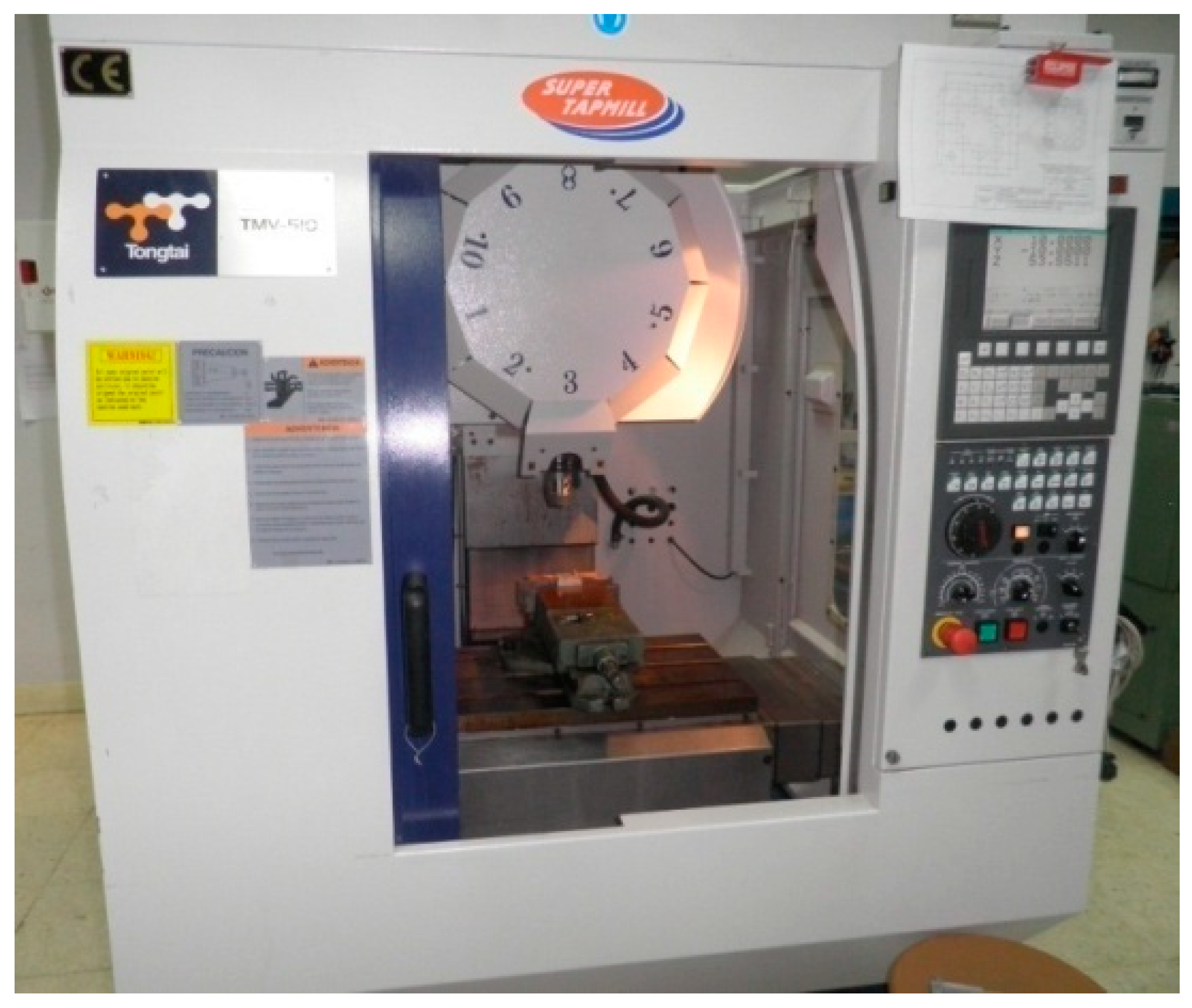
2. Materials and Methods
3. Trials
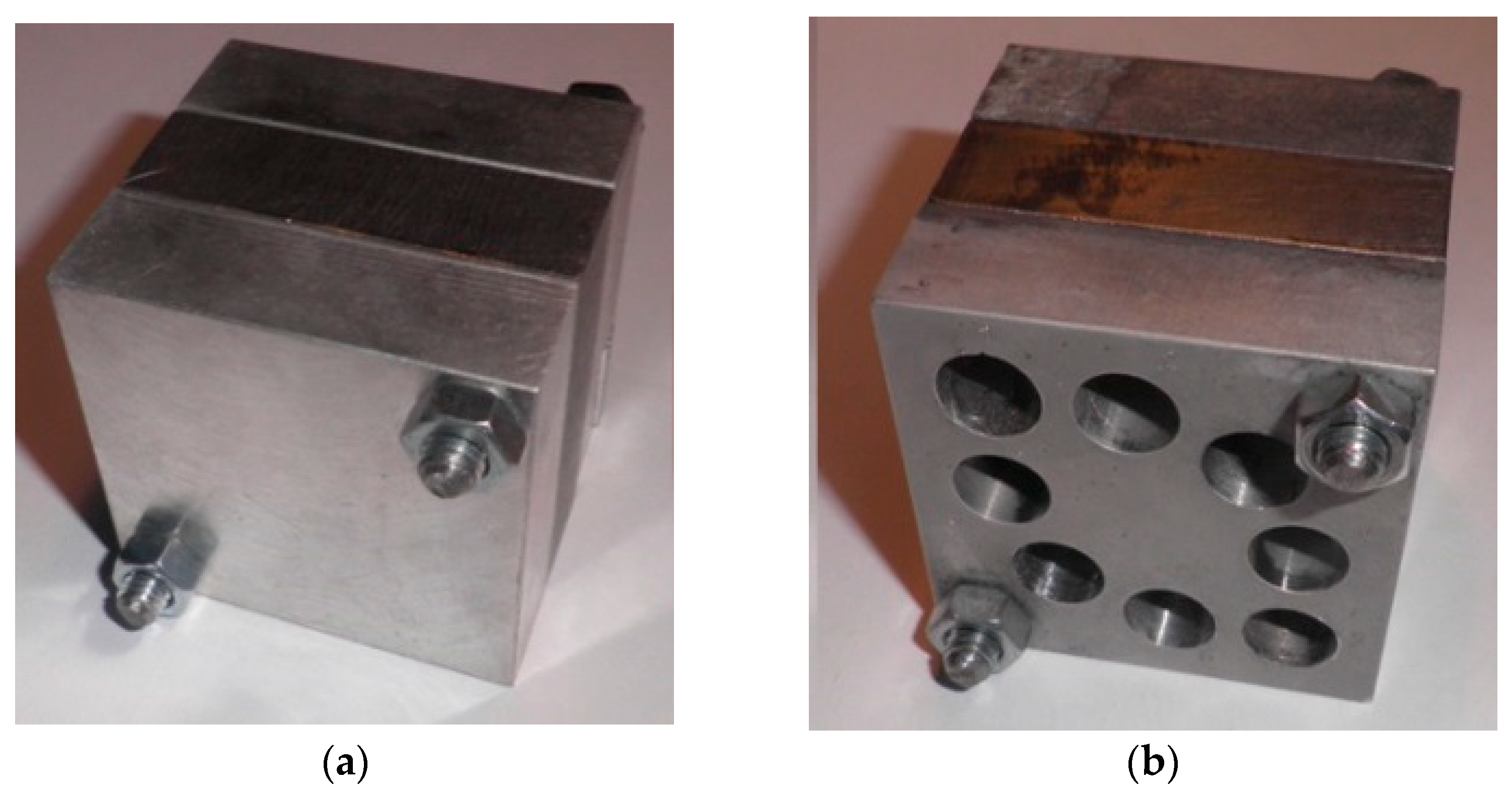
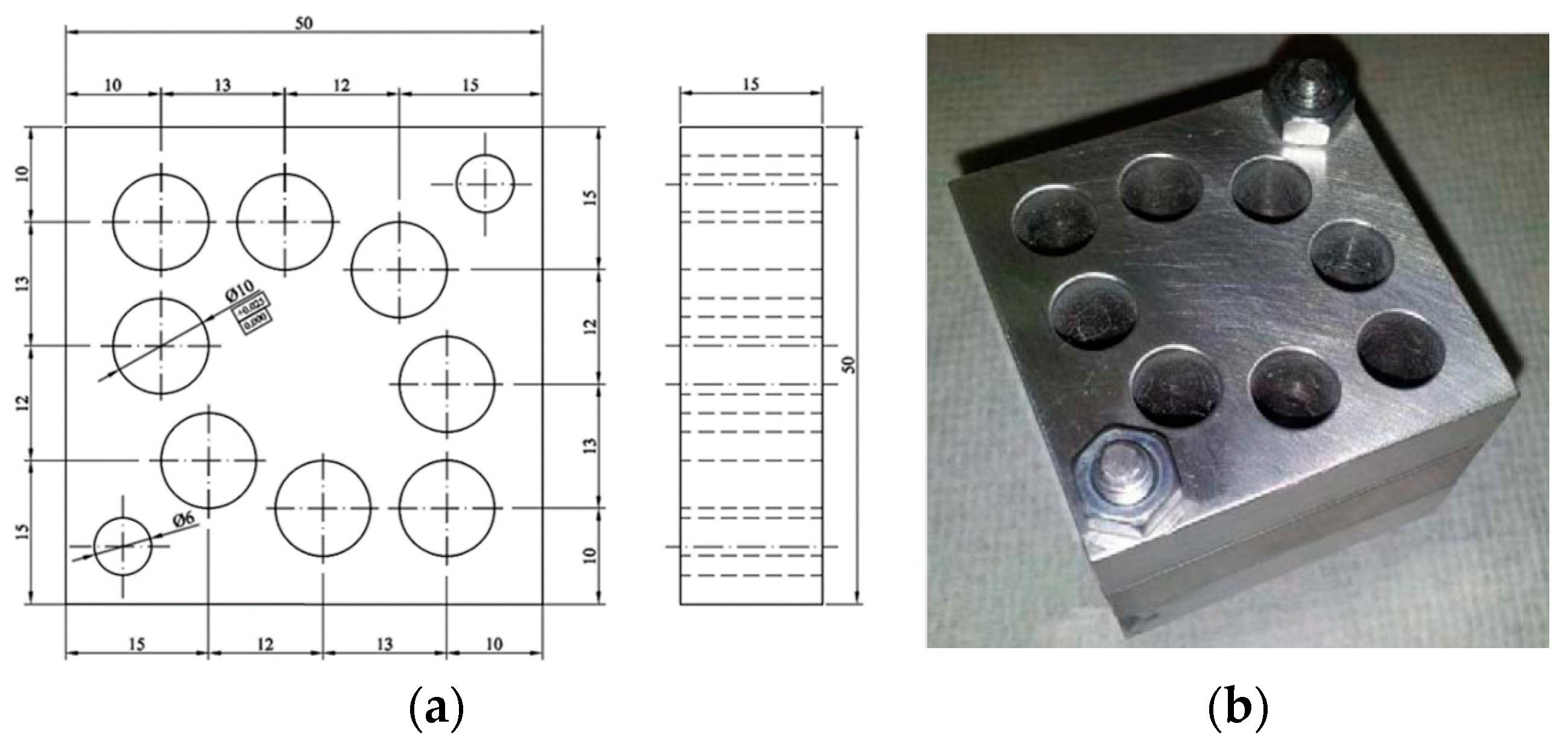
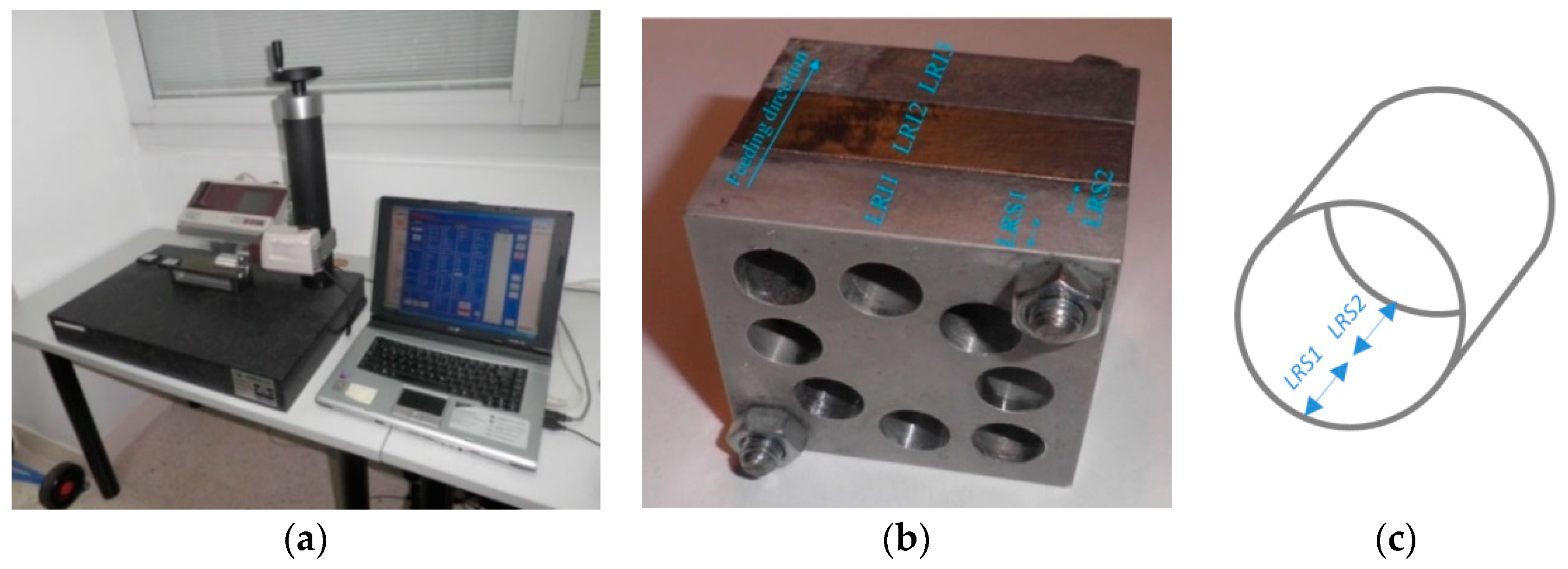
3.1. Specimens: Materials and Geometries
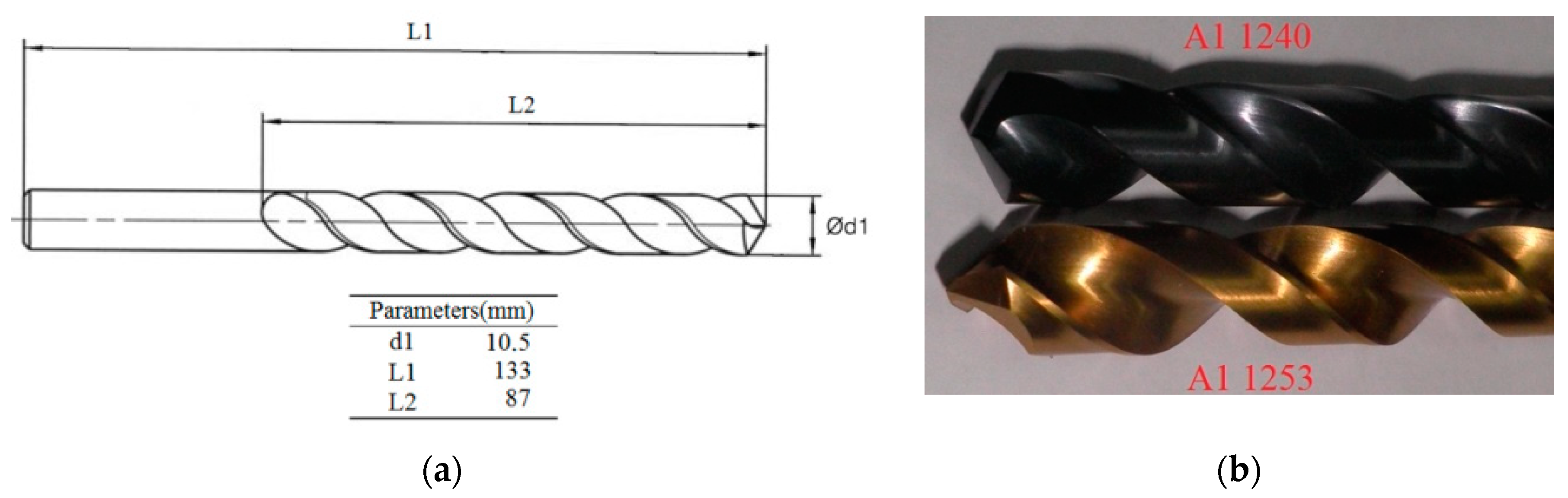
3.2. Tools
3.3. Cutting Parameters
3.4. Measurement Locations
3.5. Factors and Levels Selected
4. Results, Analysis, and Discussion
4.1. Results
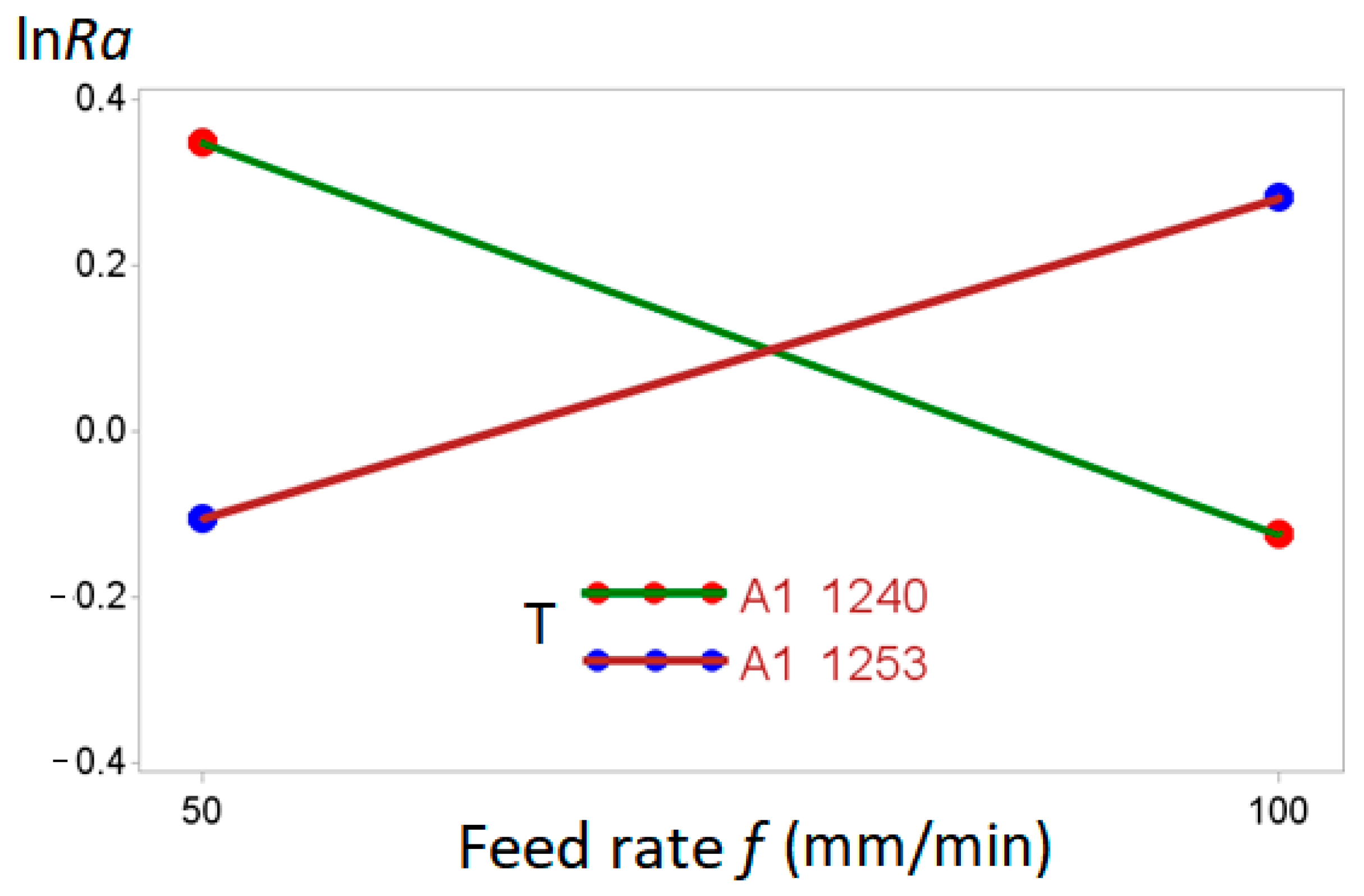
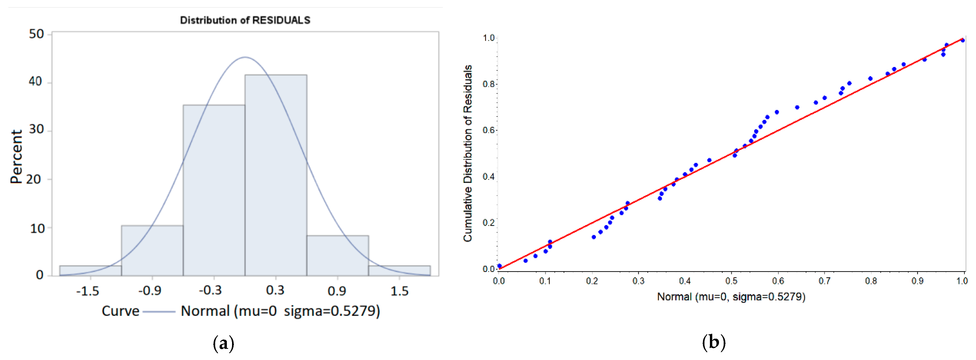
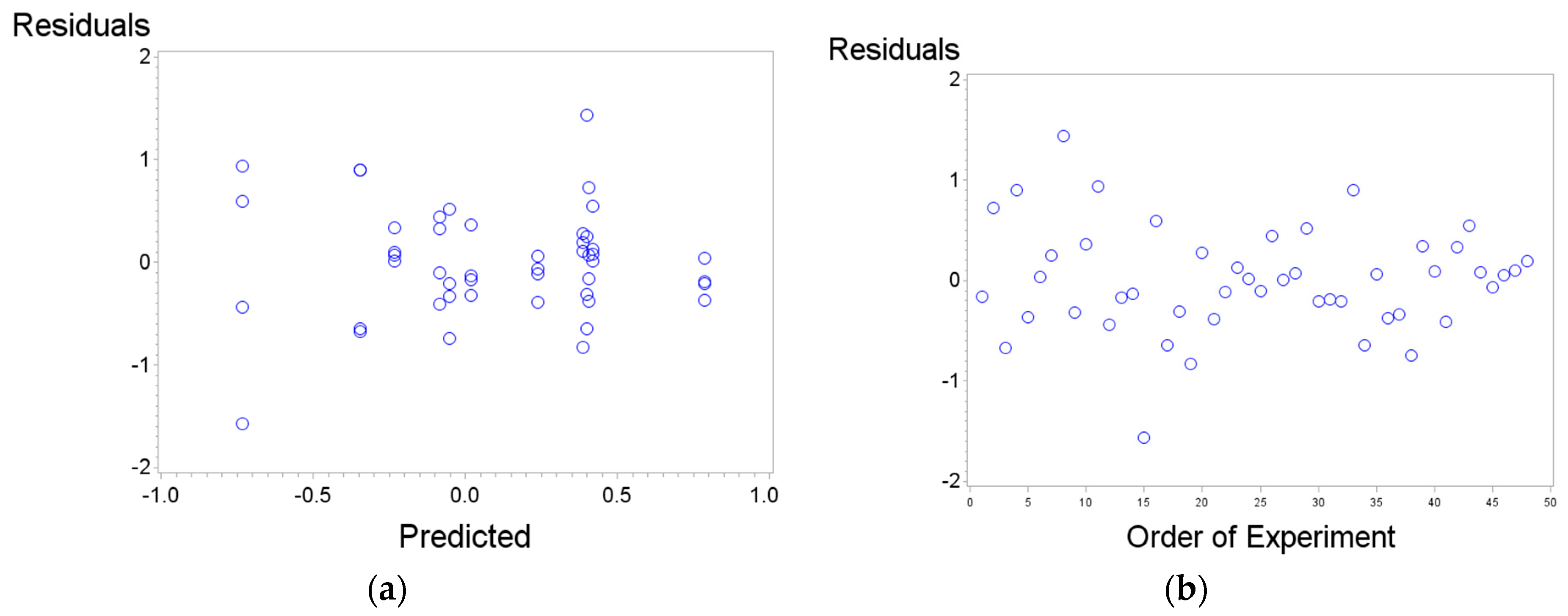
4.2. Analysis and Discussion
4.3. Technological Point of View
5. Conclusions
Author Contributions
Funding
Acknowledgments
Conflicts of Interest
References
- Pervaiz, S.; Deiab, I.; Darras, B. Power consumption and tool wear assessment when machining titanium alloys. Int. J. Precis. Eng. Manuf. 2013, 14, 925–936. [Google Scholar] [CrossRef]
- Calamaz, M.; Dominique, C.; Franck, G. A new material model for 2D numerical simulation of serrated chip formation when machining titanium alloy Ti–6Al–4V. Int. J. Mach. Tools Manuf. 2008, 48, 275–288. [Google Scholar] [CrossRef] [Green Version]
- Khanna, N.; Davim, J.P. Design-of-Experiments application in machining titanium alloys for aerospace structural components. Measurement 2015, 61, 280–290. [Google Scholar] [CrossRef]
- Wyen, C.F.; Wegener, K. Influence of cutting edge radius on cutting forces in machining titanium. CIRP Ann. 2010, 59, 93–96. [Google Scholar] [CrossRef]
- Kuttolamadom, M.; Joshua, J.; Laine, M.; Von Oehsen, J.; Kurfess, T.; Ziegert, J. High performance computing simulations to identify process parameter designs for profitable titanium machining. J. Manuf. Syst. 2017, 43, 235–247. [Google Scholar] [CrossRef]
- Jackson, M.J.; Novakov, T.; Whitfield, M.; Robinson, G.; Handy, R.; Sein, H.; Ahmed, W. VFCVD Diamond-Coated cutting tools for micro-machining titanium alloy Ti6Al4V. Int. J. Adv. Manuf. Technol. 2017, 92, 2881–2918. [Google Scholar] [CrossRef]
- Pervaiz, S.; Amir, R.; Ibrahim, D.; Cornel, M.N. An experimental investigation on effect of minimum quantity cooling lubrication (MQCL) in machining titanium alloy (Ti6Al4V). Int. J. Adv. Manuf. Technol. 2016, 87, 1371–1386. [Google Scholar] [CrossRef]
- Yang, X.P.; Liu, C.R. Machining titanium and its alloys. Mach. Sci. Technol. 1999, 3, 107–139. [Google Scholar] [CrossRef]
- Hoyne, A.C.; Nath, C.; Kapoor, S.G. On cutting temperature measurement during titanium machining with an atomization-based cutting fluid spray system. J. Manuf. Sci. Eng. 2015, 137, 024502. [Google Scholar] [CrossRef]
- Liu, Z.Q.; Xu, J.Y.; Han, S.; Chen, M. A coupling method of response surfaces (CRSM) for cutting parameters optimization in machining titanium alloy under minimum quantity lubrication (MQL) condition. Int. J. Precis. Eng. Manuf. 2013, 14, 693–702. [Google Scholar] [CrossRef]
- Ramesh, S.; Karunamoorthy, L.; Palanikumar, K. Fuzzy modeling and analysis of machining parameters in machining titanium alloy. Mater. Manuf. Process. 2008, 23, 439–447. [Google Scholar] [CrossRef]
- Revuru, R.S.; Zhang, J.Z.; Posinasetti, N.R.; Kidd, T. Optimization of titanium alloys turning operation in varied cutting fluid conditions with multiple machining performance characteristics. Int. J. Adv. Manuf. Technol. 2018, 95, 1451–1463. [Google Scholar] [CrossRef]
- Sun, J.; Guo, Y.B. Material flow stress and failure in multiscale machining titanium alloy Ti-6Al-4V. Int. J. Adv. Manuf. Technol. 2009, 41, 651–659. [Google Scholar] [CrossRef]
- Sun, S.; Brandt, M.; Dargusch, M.S. Characteristics of cutting forces and chip formation in machining of titanium alloys. Int. J. Mach. Tools Manuf. 2009, 49, 561–568. [Google Scholar] [CrossRef]
- Sima, M.; Tuğrul, Ö. Modified material constitutive models for serrated chip formation simulations and experimental validation in machining of titanium alloy Ti–6Al–4V. Int. J. Mach. Tools Manuf. 2010, 50, 943–960. [Google Scholar] [CrossRef]
- Liu, Z.; Qinglong, A.; Jinyang, X.; Ming, C.; Shu, H. Wear performance of (Nc-AlTiN)/(a-Si3N4) coating and (Nc-AlCrN)/(a-Si3N4) coating in high-speed machining of titanium alloys under dry and minimum quantity lubrication (MQL) conditions. Wear 2013, 305, 249–259. [Google Scholar] [CrossRef]
- Kannan, S.; Kishawy, H.A. Tribological aspects of machining aluminium metal matrix composites. J. Mater. Process. Technol. 2008, 198, 399–406. [Google Scholar] [CrossRef]
- Sreejith, P.S. Machining of 6061 aluminium alloy with MQL, dry and flooded lubricant conditions. Mater. Lett. 2008, 62, 276–278. [Google Scholar] [CrossRef]
- Nouari, M.; List, G.; Girot, F.; Coupard, D. Experimental analysis and optimisation of tool wear in dry machining of aluminium alloys. Wear 2003, 255, 1359–1368. [Google Scholar] [CrossRef]
- Kelly, J.F.; Cotterell, M.G. Minimal lubrication machining of aluminium alloys. J. Mater. Process. Technol. 2002, 120, 327–334. [Google Scholar] [CrossRef]
- Davoodi, B.; Tazehkandi, A.H. Experimental investigation and optimization of cutting parameters in dry and wet machining of aluminum alloy 5083 in order to remove cutting fluid. J. Clean. Prod. 2014, 68, 234–242. [Google Scholar] [CrossRef]
- Kouadri, S.; Necib, K.; Atlati, S.; Haddag, B.; Nouari, M. Quantification of the chip segmentation in metal machining: Application to machining the aeronautical aluminium alloy AA2024-T351 with cemented carbide tools WC-Co. Int. J. Mach. Tools Manuf. 2013, 64, 102–113. [Google Scholar] [CrossRef]
- Hovsepian, P.E.; Luo, Q.; Robinson, G.; Pittman, M.; Howarth, M.; Doerwald, D.; Tietema, R.; Sim, W.M.; Deeming, A.; Zeus, T. TiAlN/VN superlattice structured PVD coatings: A new alternative in machining of aluminium alloys for aerospace and automotive components. Surf. Coat. Technol. 2006, 201, 265–272. [Google Scholar] [CrossRef]
- Arumugam, P.U.; Malshe, A.P.; Batzer, S.A. Dry machining of aluminum–silicon alloy using polished CVD diamond-coated cutting tools inserts. Surf. Coat. Technol. 2006, 200, 3399–3403. [Google Scholar] [CrossRef]
- Nouari, M.; List, G.; Girot, F.; Géhin, D. Effect of machining parameters and coating on wear mechanisms in dry drilling of aluminium alloys. Int. J. Mach. Tools Manuf. 2005, 45, 1436–1442. [Google Scholar] [CrossRef]
- Sánchez, J.M.; Rubio, E.; Álvarez, M.; Sebastián, M.A.; Marcos, M. Microstructural characterisation of material adhered over cutting tool in the dry machining of aerospace aluminium alloys. J. Mater. Process. Technol. 2005, 164, 911–918. [Google Scholar] [CrossRef]
- Pu, Z.; Umbrello, D.; Dillon, O.W.; Lu, T.; Puleo, D.A.; Jawahir, I.S. Finite element modeling of microstructural changes in dry and cryogenic machining of AZ31B magnesium alloy. J. Manuf. Process. 2014, 16, 335–343. [Google Scholar] [CrossRef]
- Denkena, B.; Lucas, A. Biocompatible magnesium alloys as absorbable implant materials—Adjusted surface and subsurface properties by machining processes. CIRP Ann. 2007, 56, 113–116. [Google Scholar] [CrossRef]
- Gariboldi, E. Drilling a magnesium alloy using PVD coated twist drills. J. Mater. Process. Technol. 2003, 134, 287–295. [Google Scholar] [CrossRef]
- Dinesh, S.; Senthilkumar, V.; Asokan, P.; Arulkirubakaran, D. Effect of cryogenic cooling on machinability and surface quality of bio-degradable ZK60 mg alloy. Mater. Des. 2015, 87, 1030–1036. [Google Scholar] [CrossRef]
- Menezes, P.L.; Kailas, K.S.V. Influence of roughness parameters on coefficient of friction under lubricated conditions. Sadhana 2008, 33, 181–190. [Google Scholar] [CrossRef] [Green Version]
- Pu, Z.; Outeiro, J.C.; Batista, A.C.; Dillon, O.W.; Puleo, D.A.; Jawahir, I.S. Enhanced surface integrity of AZ31B mg alloy by cryogenic machining towards improved functional performance of machined components. Int. J. Mach. Tools Manuf. 2012, 56, 17–27. [Google Scholar] [CrossRef]
- Shokrani, A.; Dhokia, V.; Newman, S.T. Environmentally conscious machining of difficult-to-machine materials with regard to cutting fluids. Int. J. Mach. Tools Manuf. 2012, 57, 83–101. [Google Scholar] [CrossRef] [Green Version]
- Shaharun, M.A.; Ahmad, R.Y. Effects of irregular tool geometry and machining process parameters on the wavelength performance of process damping in machining titanium alloy at low cutting speed. Int. J. Adv. Manuf. Technol. 2016, 85, 1019–1033. [Google Scholar] [CrossRef]
- Rubio, E.M.; Sáenz de Pipaón, J.M.; Villeta, M.; Sebastián, M.A. Experimental study for improving repair operations of pieces of magnesium UNS M11311 obtained by dry turning. In Proceedings of the 12th CIRP Conference on Modelling of Machining, San Sebastian, Spain, 7–8 May 2009; pp. 819–826. [Google Scholar]
- Villeta, M.; Agustina, B.; Sáenz de Pipaón, J.M.; Rubio, E.M. Efficient optimisation of machining processes based on technical specifications for surface roughness: Application to magnesium pieces in the aerospace industry. Int. J. Adv. Manuf. Technol. 2011, 60, 1237–1246. [Google Scholar] [CrossRef]
- Villeta, M.; Rubio, E.M.; Sáenz de Pipaón, J.M.; Sebastián, M.A. Surface finish optimization of magnesium pieces obtained by dry turning based on Taguchi techniques and statistical tests. Mater. Manuf. Process. 2011, 26, 1503–1510. [Google Scholar] [CrossRef]
- Rubio, E.M.; Valencia, J.L.; Saá, A.J.; Carou, D. Experimental study of the dry facing of magnesium pieces based on the surface roughness. Int. J. Precis. Eng. Manuf. 2013, 14, 995–1001. [Google Scholar] [CrossRef]
- Rubio, E.M.; Villeta, M.; Carou, D.; Saá, A.J. Comparative analysis of sustainable cooling systems in intermittent turning of magnesium pieces. Int. J. Precis. Eng. Manuf. 2014, 15, 929–940. [Google Scholar] [CrossRef]
- Rubio, E.M.; Valencia, J.L.; Agustina, B.; Saá, A.J. Tool selection based on surface roughness in dry facing repair operations of magnesium pieces. Int. J. Mater. Prod. Technol. 2014, 48, 116–134. [Google Scholar] [CrossRef]
- Carou, D.; Rubio, E.M.; Davim, J.P. Discontinuous cutting: Failure mechanisms, tool materials and temperature study—A review. Rev. Adv. Mater. Sci. 2014, 38, 110–124. [Google Scholar]
- Carou, D.; Rubio, E.M.; Lauro, C.H.; Davim, J.P. Experimental investigation on surface finish during intermittent turning of UNS M11917 magnesium alloy under dry and near dry machining conditions. Measurement 2014, 56, 136–154. [Google Scholar] [CrossRef]
- Bureau of Labor Statistics, Productivity and Costs by Industry: Manufacturing and Mining Industries-2017, Economic New Release, 2018. Available online: www.bls.gov/news.release/pdf/prin.pdf (accessed on 3 July 2018).
- Rubio, E.M.; de Agustina, B.; Marín, M.M.; Bericua, A. Cooling systems based on cold compressed air: A review of the applications in machining processes. Proc. Eng. 2015, 132, 413–418. [Google Scholar] [CrossRef]
- Carou, D.; Rubio, E.M.; Davim, J.P. A note on the use of the minimum quantity lubrication (MQL) system in turning. Ind. Lubr. Tribol. 2015, 67, 256–261. [Google Scholar] [CrossRef]
- Carou, D.; Rubio, E.M.; Davim, J.P. Analysis of ignition risk in intermittent turning of UNS M11917 magnesium alloy at low cutting speeds based on the chip morphology. Proc. Inst. Mech. Eng. Part B J. Eng. Manuf. 2015, 229, 365–371. [Google Scholar] [CrossRef]
- Carou, D.; Rubio, E.M.; Lauro, C.H.; Davim, J.P. Experimental investigation on finish intermittent turning of UNS M11917 magnesium alloy under dry machining. Int. J. Adv. Manuf. Technol. 2015, 75, 1417–1429. [Google Scholar] [CrossRef]
- Carou, D.; Rubio, E.M.; Lauro, C.H.; Davim, J.P. The effect of minimum quantity lubrication in the intermittent turning of magnesium based on vibration signals. Measurement 2016, 94, 338–343. [Google Scholar] [CrossRef]
- Carou, D.; Rubio, E.M.; Agustina, B.; Marín, M.M. Experimental study for effective and sustainable repair and maintenance of bars made of Ti-6Al-4V alloy application to the aeronautic industry. J. Clean. Prod. 2017, 164, 465–475. [Google Scholar] [CrossRef]
- Ben Artzy, A.; Munitz, A.; Kohn, G.; Bronfin, B.; Shtechman, A. Joining of light hybrid constructions made of magnesium and aluminum alloys. TMS Ann. Meet. 2002, 1, 295–302. [Google Scholar]
- Ashby, M.F.; Brécht, Y.J.M. Designing hybrid materials. Acta Mater. 2003, 51, 5801–5821. [Google Scholar] [CrossRef]
- Amancio, S. Innovative Solid-State Spot Joining Methods for Fiber Composites and Metal-Polymer Hybrid Structures; Joining in Car Body; Helmholtz-ZentrumGeesthacht: Geesthacht, Germany, 2012; pp. 1–47. [Google Scholar]
- Gururaja, M.N.; Rao, A.N.H. A review on recent applications and future prospectus of hybrid composites. Int. J. Soft Comput. Eng. 2012, 1, 352–355. [Google Scholar]
- Suryawanshi, B.K.; Prajitsen, G.D. Review of design of hybrid aluminum/composite drive shaft for automobile. Int. J. Innov. Technol. Explor. Eng. 2013, 2, 259–266. [Google Scholar]
- Lee, D.; Morillo, C.; Oller, S.; Bugeda, G.; Oñate, E. Robust design optimization of advance hybrid (fiber-metal) composite structures. Compos. Struct. 2013, 99, 181–192. [Google Scholar] [CrossRef]
- Rubio, E.M.; Villeta, M.; Valencia, J.L.; Sáenz de Pipaón, J.M. Experimental study for improving repair of magnesium-aluminium hybrid parts by turning processes. Metals 2018, 8, 59. [Google Scholar] [CrossRef]
- Rubio, E.M.; Sáenz de Pipaón, J.M.; Valencia, J.L.; Villeta, M. Design, Manufacturing and Machining Trials of Magnesium Based Hybrid Parts, Machining of Light Alloys: Aluminium, Titanium and Magnesium; CRC-Press: Boca Raton, FL, USA, 2018; in press. [Google Scholar]
- Zakaria, B.; Yazid, H. Friction stir welding of disimilar materials Aluminum Al6061-T6 to ultra low carbon steel. Metals 2017, 7, 42. [Google Scholar]
- Casalino, G. Advances in welding metal alloys, Disimilar metals and additively manufactured parts. Metals 2017, 7, 32. [Google Scholar] [CrossRef]
- Casalino, G.; Guglielmi, P.; Lorusso, V.D.; Mortello, M.; Peyre, P.; Sorgente, D. Lasser offset welding of AZ31B magnesium alloy to 316 stainless steel. J. Mater. Process. Technol. 2017, 242, 49–59. [Google Scholar] [CrossRef]
- Li, Y.; Liu, C.; Yu, H.; Zhao, F.; Wu, Z. Numerical simulation of Ti/Al bimetal composite fabricated by explosive welding. Metals 2017, 7, 407. [Google Scholar] [CrossRef]
- Wagner, F.; Zerner, I.; Kreimeyer, M.; Seefeld, T.; Sepold, G. Characterization and properties of dissimilar metal combinations of Fe/Al and Ti/Al sheet materials. In Proceedings of the ICALEO’01, Orlando, FL, USA, 15–18 October 2001. [Google Scholar]
- Luo, J.G.; Acoff, V.L. Interfacial reactions of titanium and aluminum during diffusion welding. Weld. J. 2000, 79, 239–243. [Google Scholar]
- Sáenz de Pipaón, M.J. Diseño y Fabricación de Probetas de Componentes Híbridos con Aleaciones de Magnesio para Ensayos de Mecanizado. Ph.D. Thesis, UNED (Universidad Nacional de Educación a Distancia), Madrid, Spain, 2013. [Google Scholar]
- Qi, X.; Song, G. Interfacial structure of the joints between magnesium alloy and mild steel with nickel as interlayer laser-TIG welding. Mater. Des. 2010, 31, 605–609. [Google Scholar] [CrossRef]
- Nasiri, A.M.; Li, L.; Kim, S.H.; Zhou, Y.; Weckman, D.C.; Nguyen, T.C. Microstructure and properties of laser brazed magnesium to coated steel. Weld. J. 2011, 90, 211–219. [Google Scholar]
- Nasiri, A.M.; Weckman, D.C.; Zhou, Y. Interfacial microstructure of diode laser brazed AZ31B magnesium to steel sheet using a nickel interlayer. Weld. J. 2013, 92, 1S–10S. [Google Scholar]
- Dau, J.; Lauter, C.; Damerow, U.; Homberg, W.; Tröster, T. Multi-material systems for tailored automotive structural components. In Proceedings of the 18th International Conference on Composite Materials, Jeju Island, Korea, 21–26 August 2011. [Google Scholar]
- Frantz, M.; Lauter, C.; Tröster, T. Advanced manufacturing technologies for automotive structures in multi-material design consisting of high-strength steels and CFRP. In Proceedings of the 56th International Scientific Colloquium, Ilmenau, Germany, 12–16 September 2011. [Google Scholar]
- DRL. Innovation Report 2011; Institute of Composites Structures and Adaptative Systems: Braunschweig, Germany, 2011. [Google Scholar]
- Amin, N. Titanium Alloys—Towards Achieving Enhanced Properties for Diversified Applications. Edited by A.K.M. Nurul Amin, 2012. Available online: www.intechopen.com (accessed on 1 July 2018).
- Bisker, J.; Christman, T.; Allison, T.; Goranson, H.; Landmesser, J.; Minister, A.; Plonski, R. DOE Handbook, Primer on Spontaneous Heating and Pyrophoricity; U.S. Department of Energy: Washington, DC, USA, 1994; pp. 1–68.
- NanoMAG. Hydro Magnesium’s Machining Magnesium; Technical Document; NanoMAG: Livonia, MI, USA, 2009; Available online: http://nanomag.us (accessed on 22 November 2017).
- Layens, C.; Peters, M. Titanium and Titanium Alloys. Fundamentals and Applications; Wiley-VCH Verlag GmbH & Co.: Weinheim, Germany, 2003. [Google Scholar]
- Sáenz de Pipaón, J.M.; Rubio, E.M.; Villeta, M.; Sebastián, M.A. Analysis of the chips obtained by dry turning of UNS M11311 magnesium. In Proceedings of the 3rd Manufacturing Engineering Society International Conference 2009, Alcoy, Spain, 17–19 June 2009; pp. 33–38. [Google Scholar]
- Sáenz de Pipaón, J.M.; Rubio, E.M.; Villeta, M.; Sebastián, M.A. Selection of the cutting tools and conditions for the low speed turning of bars of magnesium UNS M11311 based on the surface roughness. In Innovative Production Machines and Systems; Whittles Publishing: Scotland, UK, 2010; pp. 174–179. ISBN 978-184995-006-0. [Google Scholar]
- El-CGizawy, A.S.; Khasawneh, F.A.; Bogis, H. Drilling process design for hybrid structures of polymer composites over titanium alloy. J. Mater. Sci. Eng. 2016, 5, 243. [Google Scholar] [CrossRef]
- Matsumara, T.; Tamura, S. Cutting simulation of titanium alloy drilling with energy analysis and FEM. In Proceedings of the 15th CIRP Conference on Modelling of Machining Operations, Karlsruhe, Germany, 11–12 June 2015; pp. 252–257. [Google Scholar]
- Poutord, A.; Rossi, F.; Paulachon, G.; M’Saoubi, R.; Abrivard, G. Local approach of wear in drilling Ti6Al4V/CFRP for stack modelling. In Proceedings of the 14th CIRP Conference on Modelling of Machining Operations, Turin, Italy, 13–14 June 2013; pp. 316–321. [Google Scholar]
- Shetty, P.K.; Shetty, R.; Shetty, D.; Rehaman, F. Machinability study on dry drilling of titanium alloy Ti-6Al-4V using L9 othogonal array. Procedia Mater. Sci. 2014, 5, 2605–2614. [Google Scholar] [CrossRef]
- Ramulu, M.; Spaulding, M. Drilling of hybrid titanium composite laminate (HTCL) with electrical discharge machining. Materials 2016, 9, 746. [Google Scholar] [CrossRef] [PubMed]
- Grasin, K.; Ayvar-Soberanis, S. Evaluation of workpiece temperature during drilling of GLARE fiber metal laminates using infrared techniques: Effect of cutting parameters, fiber orientation and spray mist application. Materials 2016, 9, 622. [Google Scholar] [CrossRef]
- Abdulgadir, M.; Demir, B.; Emre Turam, M. Hybrid reinforced magnesium matrix composites (Mg/Sic/GNPs): Drilling investigation. Metals 2018, 8, 215. [Google Scholar] [CrossRef]
- Li, M.; Huang, M.; Jiang, X. Study on burr occurrence and surface integrity during slot milling of multidirectional and plain woven CFRPs. Int. J. Adv. Manuf. Technol. 2018, 97, 163–173. [Google Scholar] [CrossRef]
- Bellini, C.; Polini, W.; Sorrentino, L. A new class of thin composite parts for small batch productions. Adv. Compos. Lett. 2014, 23, 115–120. [Google Scholar]
- Liao, B.B.; Liu, P.F. Finite element analysis of dynamic progressive failure properties of GLARE hybrid laminates under low-velocity impact. J. Compos. Mater. 2018, 52, 1317–1330. [Google Scholar] [CrossRef]
- Montgomery, D.C. Design and Analysis of Experiments; John Wiley & Sons, Inc.: Hoboken, NJ, USA, 2017. [Google Scholar]
- ISO. Geometrical Product Specifications (GPS) Surface Texture: Profile Method. Rules and Procedures for the Assessment of Surface Texture; International Organization for Standardization: Geneva, Switzerland, 1998. [Google Scholar]
- Zhang, P.F.; Churi, N.J.; Treadwell, C. Mechanical drilling processes for titanium alloys: A literature review. Mach. Sci. Technol. 2008, 12, 417–444. [Google Scholar] [CrossRef]
- Celik, Y.M. Investigating the effects of cutting parameters on the hole quality in drilling the Ti-6Al-4V alloy. Mater. Technol. 2014, 48, 653–659. [Google Scholar]
- Rahim, E.A.; Sharif, S.; Sasahara, H. Machinability of titanium alloys in drilling. Chapter 6. In Titanium Alloys-Towards Achieving Enhanced Properties for Diversified Applications; Edited by A.K.M. Nurul Amin; 2012; Available online: www.intechopen.com (accessed on 1 July 2018).
- Chong, K.Z.; Shih, T.S. Optimizing drilling conditions for AZ61A magnesium alloy. Mater. Trans. 2002, 43, 2148–2156. [Google Scholar] [CrossRef]
- Taguchi, G. System of Experimental Design: Engineering Methods to Optimize Quality and Mimimize Costs, 1st ed.; Kraus International Publications: New York, NY, USA, 1987; Volume 1. [Google Scholar]
- The American Society of Mechanical Engineers. Surface Texture: Surface Roughness, Waviness and Lay; ANSI/ASME B46.1-2009; ASME: New York, NY, USA, 2010. [Google Scholar]


| Factor | Level |
|---|---|
| Feed rate, f (mm/min) | f1, f2 |
| Cutting speed, V (m/min) | V1, V2 |
| Tool coating type, T | T1, T2 |
| Location with respect to the specimen, LRS | LRS1, LRS2 |
| Location with respect to the insert, LRI | LRI1, LRI2, LRI3 |
| T | V (m/min) | f (mm/min) | LRI | LRS | |
|---|---|---|---|---|---|
| T1 | V1 | f2 | LRI2 | LRS1 | LRS2 |
| T1 | V1 | f2 | LRI1 | LRS1 | LRS2 |
| T1 | V1 | f2 | LRI3 | LRS1 | LRS2 |
| T1 | V1 | f1 | LRI3 | LRS1 | LRS2 |
| T1 | V1 | f1 | LRI2 | LRS1 | LRS2 |
| T1 | V1 | f1 | LRI1 | LRS1 | LRS2 |
| T1 | V2 | f1 | LRI2 | LRS1 | LRS2 |
| T1 | V2 | f1 | LRI1 | LRS1 | LRS2 |
| T1 | V2 | f1 | LRI3 | LRS1 | LRS2 |
| T2 | V1 | f1 | LRI3 | LRS1 | LRS2 |
| T2 | V1 | f1 | LRI2 | LRS1 | LRS2 |
| T2 | V1 | f1 | LRI1 | LRS1 | LRS2 |
| T2 | V2 | f2 | LRI3 | LRS1 | LRS2 |
| T2 | V2 | f2 | LRI2 | LRS1 | LRS2 |
| T2 | V2 | f2 | LRI1 | LRS1 | LRS2 |
| T1 | V2 | f2 | LRI3 | LRS1 | LRS2 |
| T1 | V2 | f2 | LRI1 | LRS1 | LRS2 |
| T1 | V2 | f2 | LRI2 | LRS1 | LRS2 |
| T2 | V1 | f2 | LRI1 | LRS1 | LRS2 |
| T2 | V1 | f2 | LRI2 | LRS1 | LRS2 |
| T2 | V1 | f2 | LRI3 | LRS1 | LRS2 |
| T2 | V2 | f1 | LRI1 | LRS1 | LRS2 |
| T2 | V2 | f1 | LRI2 | LRS1 | LRS2 |
| T2 | V2 | f1 | LRI3 | LRS1 | LRS2 |
| UNS M11917 (AZ91D) | UNS R56400 (Ti-6Al-4V) |
|---|---|
| Al 8.30–9.70% | Al 5.5–6.75% |
| Cu ≤ 0.03% | C ≤ 0.08% |
| Fe ≤ 0.005% | H ≤ 0.015% |
| Mg 90% | Fe ≤ 0.4% |
| Mn ≥ 0.13% | N ≤ 0.03% |
| Ni ≤ 0.002% | O ≤ 0.2% |
| Si ≤ 0.1% | Ti 87.725–91% |
| Zn 0.35–1% | Zn 3.5–4.5% |
| Factor | Level Value |
|---|---|
| Feed rate, f, (mm/min) | 50/100 |
| Cutting speed, V, (m/min) | 20/25 |
| Type of tool, T | A1 1253/A1 1240 |
| Location with respect to the specimen, LRS | Beginning of the specimen, end of the specimen |
| Location with respect to the insert, LRI | Before the insert, on the insert, after the insert |
| T | V (m/mnin) | f (mm/min) | LRI | Ra (μm) | |
|---|---|---|---|---|---|
| LRS1 | LRS2 | ||||
| A11253 | 20 | 100 | LRI2 | 1.28 | 3.09 |
| A11253 | 20 | 100 | LRI1 | 0.36 | 1.73 |
| A11253 | 20 | 100 | LRI3 | 1.52 | 2.28 |
| A11253 | 20 | 50 | LRI3 | 1.91 | 6.28 |
| A11253 | 20 | 50 | LRI2 | 0.74 | 1.46 |
| A11253 | 20 | 50 | LRI1 | 1.23 | 0.31 |
| A11253 | 25 | 50 | LRI2 | 0.86 | 0.89 |
| A11253 | 25 | 50 | LRI1 | 0.10 | 0.87 |
| A11253 | 25 | 50 | LRI3 | 0.78 | 1.09 |
| A11240 | 20 | 50 | LRI3 | 0.64 | 1.94 |
| A11240 | 20 | 50 | LRI2 | 0.86 | 1.13 |
| A11240 | 20 | 50 | LRI1 | 1.73 | 1.54 |
| A11240 | 25 | 100 | LRI3 | 0.83 | 1.43 |
| A11240 | 25 | 100 | LRI2 | 0.80 | 0.85 |
| A11240 | 25 | 100 | LRI1 | 1.59 | 0.77 |
| A11253 | 25 | 100 | LRI3 | 1.81 | 1.79 |
| A11253 | 25 | 100 | LRI1 | 1.73 | 0.37 |
| A11253 | 25 | 100 | LRI2 | 1.60 | 1.03 |
| A11240 | 20 | 100 | LRI1 | 0.68 | 0.45 |
| A11240 | 20 | 100 | LRI2 | 1.11 | 0.87 |
| A11240 | 20 | 100 | LRI3 | 0.61 | 1.28 |
| A11240 | 25 | 50 | LRI1 | 2.62 | 1.65 |
| A11240 | 25 | 50 | LRI2 | 1.19 | 1.34 |
| A11240 | 25 | 50 | LRI3 | 1.63 | 1.78 |
| Ra (μm) | f (mm/min) | V (m/min) | ||
|---|---|---|---|---|
| 50 | 100 | 20 | 25 | |
| RaLRI1 | 1.26 | 0.96 | 1.00 | 1.21 |
| RaLRI2 | 1.06 | 1.33 | 1.32 | 1.08 |
| RaLRI3 | 2.01 | 1.44 | 2.06 | 1.39 |
| Effect | DF | Sum of Squares | Mean Square | F-Value | Pr > F |
|---|---|---|---|---|---|
| LRI | 2 | 2.426 | 1.213 | 3.77 | 0.036 |
| T | 1 | 0.007 | 0.007 | 0.02 | 0.823 |
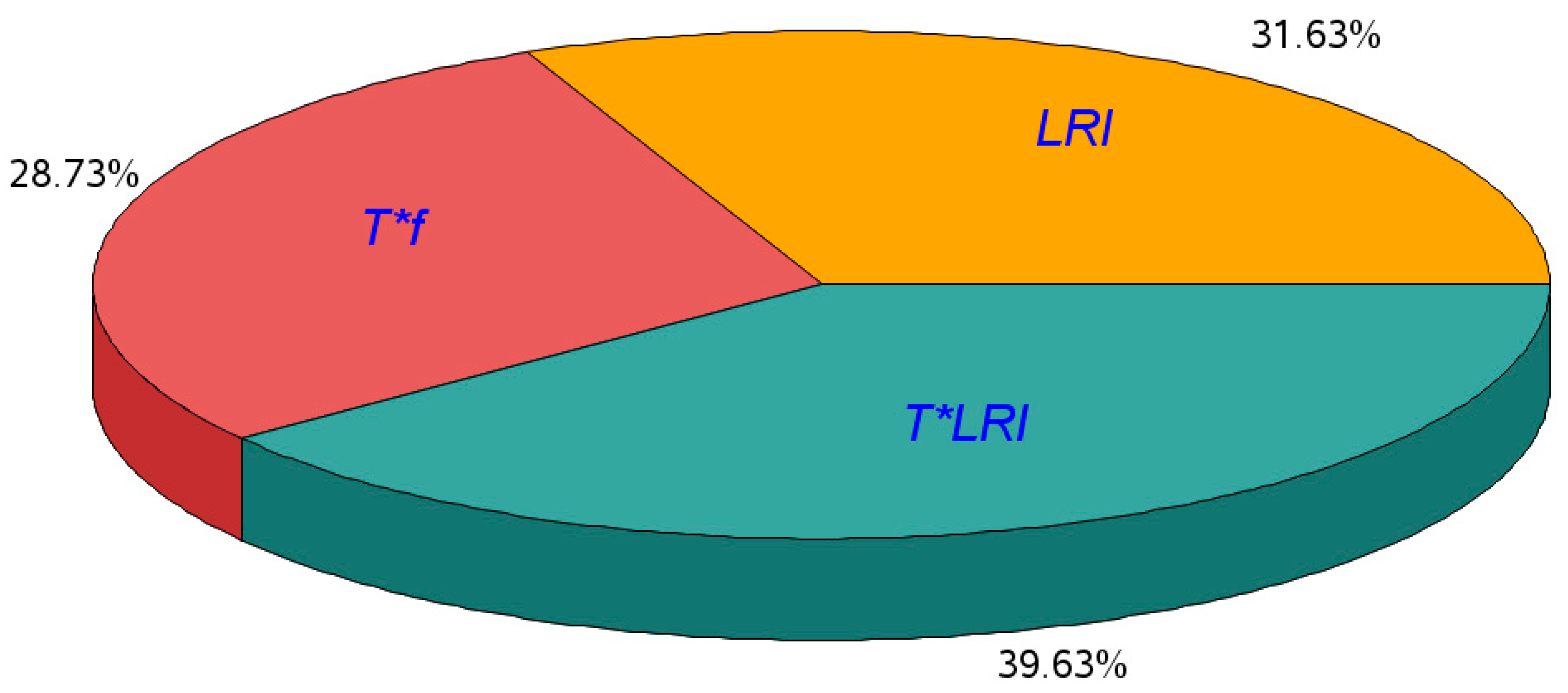
| T*LRI | 2 | 3.041 | 1.521 | 4.73 | 0.017 |
| f | 1 | 0.021 | 0.021 | 0.06 | 0.802 |
| LRI*f | 2 | 0.225 | 0.112 | 0.35 | 0.708 |
| T*f | 1 | 2.206 | 2.206 | 6.86 | 0.014 |
| LRS | 1 | 0.492 | 0.492 | 1.53 | 0.227 |
| LRI*LRS | 2 | 0.886 | 0.443 | 1.38 | 0.270 |
| T*LRS | 1 | 0.177 | 0.177 | 0.55 | 0.465 |
| f*LRS | 1 | 0.214 | 0.214 | 0.67 | 0.422 |
| V | 1 | 0.092 | 0.092 | 0.29 | 0.597 |
| LRI*V | 2 | 0.122 | 0.061 | 0.19 | 0.828 |
| T*V | 1 | 1.565 | 1.565 | 4.86 | 0.036 |
| f*V | 1 | 0.211 | 0.211 | 0.65 | 0.425 |
| V*LRS | 1 | 0.429 | 0.429 | 1.33 | 0.259 |
| Error | 27 | 8.686 | 0.322 | ||
| Total | 47 | 20.800 |
| Effect | DF | Sum of Squares | Mean Square | F-Value | Pr > F |
|---|---|---|---|---|---|
| T*f | 1 | 2.206 | 2.206 | 7.06 | 0.011 |
| LRI | 2 | 2.426 | 1.213 | 3.88 | 0.028 |
| T*LRI | 2 | 3.041 | 1.521 | 4.87 | 0.013 |
| Error | 42 | 13.127 | 0.313 | ||
| Total | 47 | 20.800 |
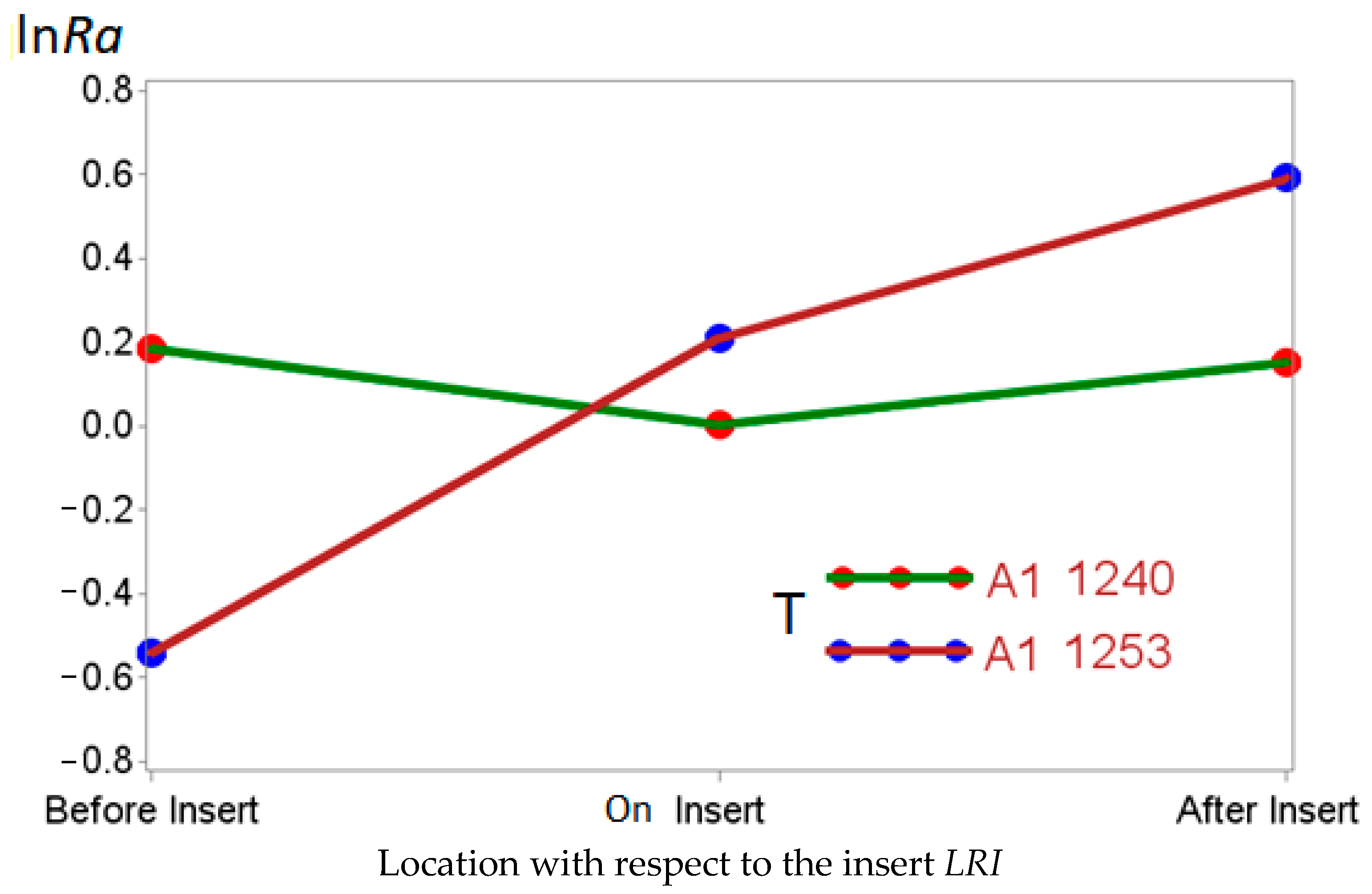
| Parameter | Designation | Estimation | Standard Error | t-Value | Pr > |t| |
|---|---|---|---|---|---|
| Intercept | µ | 0.7862 | 0.2336 | 3.37 | 0.0017 |
| A1 1253*50 (mm/min) | βγ11 | −0.3873 | 0.2336 | −1.66 | 0.1052 |
| A1 1253*100 (mm/min) | βγ12 | 0 | . | . | . |
| A1 1240*50 (mm/min) | βγ21 | −0.4004 | 0.3304 | −1.21 | 0.2326 |
| A1 1240*100 (mm/min) | βγ22 | −0.8706 | 0.3304 | −2.64 | 0.0119 |
| Before the insert | α1 | −1.1333 | 0.2861 | −3.96 | 0.0003 |
| On the insert | α2 | −0.3820 | 0.2861 | −1.34 | 0.1894 |
| After the insert | α3 | 0 | . | . | . |
| A1 1253*Before the insert | βα11 | 0 | . | . | . |
| A1 1253*On the insert | βα12 | 0 | . | . | . |
| A1 1253*After the insert | βα13 | 0 | . | . | . |
| A1 1240*Before the insert | βα21 | 1.1654 | 0.4046 | 2.88 | 0.0064 |
| A1 1240*On the insert | βα22 | 0.2335 | 0.4046 | 0.58 | 0.5671 |
| A1 1240*After the insert | βα23 | 0 | . | . | . |
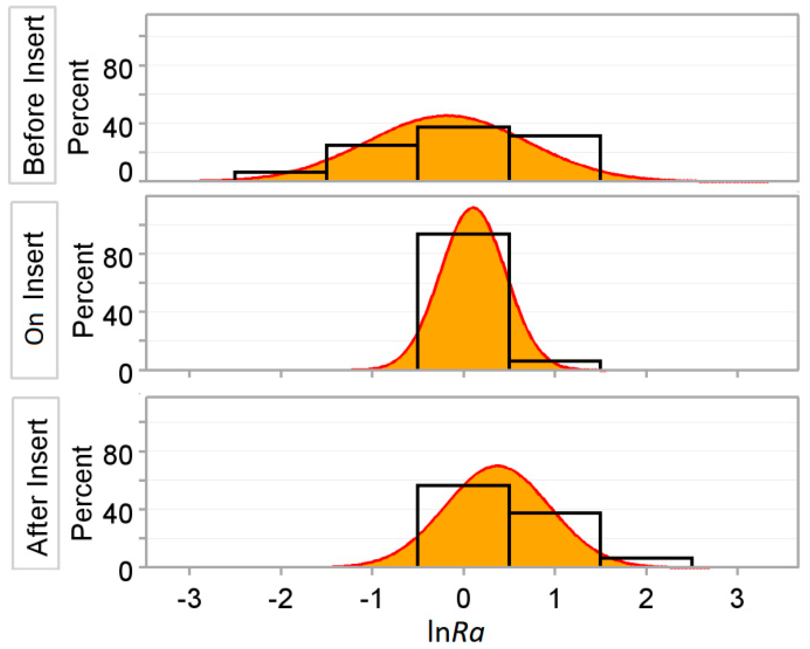
| Test for Normality | Statistic | p-Value | ||
|---|---|---|---|---|
| Shapiro–Wilk | W | 0.977919 | Pr < W | 0.4952 |
| Kolmogorov–Smirnov | D | 0.0900 | Pr > D | >0.150 |
| LRI | T | f (mm/min) | lnRa Predicted αi + βαji + βγjk | Ra Predicted (µm) exp (αi + βαji + βγjk) | Ra Predicted * (µm) exp (αi* + βαji* + βγjk*) |
|---|---|---|---|---|---|
| Before insert | A1 1253 | 50 | −0.734 | 0.48 | 0.71 (Class I) |
| Before insert | A1 1253 | 100 | −0.347 | 0.71 | |
| On insert | A1 1240 | 100 | −0.233 | 0.79 | 0.92 (Class II) |
| After insert | A1 1240 | 100 | −0.084 | 0.92 | |
| Before insert | A1 1240 | 100 | −0.052 | 0.95 | 0.95 (Class III) |
| On insert | A1 1253 | 50 | 0.017 | 1.02 | 2.20 (Class IV) |
| On insert | A1 1240 | 50 | 0.237 | 1.27 | |
| After insert | A1 1240 | 50 | 0.386 | 1.47 | |
| After insert | A1 1253 | 50 | 0.399 | 1.49 | |
| On insert | A1 1253 | 100 | 0.404 | 1.50 | |
| Before insert | A1 1240 | 50 | 0.418 | 1.52 | |
| After insert | A1 1253 | 100 | 0.786 | 2.20 |
© 2018 by the authors. Licensee MDPI, Basel, Switzerland. This article is an open access article distributed under the terms and conditions of the Creative Commons Attribution (CC BY) license (http://creativecommons.org/licenses/by/4.0/).
Share and Cite
Rubio, E.M.; Villeta, M.; Valencia, J.L.; Sáenz de Pipaón, J.M. Cutting Parameter Selection for Efficient and Sustainable Repair of Holes Made in Hybrid Mg–Ti–Mg Component Stacks by Dry Drilling Operations. Materials 2018, 11, 1369. https://doi.org/10.3390/ma11081369
Rubio EM, Villeta M, Valencia JL, Sáenz de Pipaón JM. Cutting Parameter Selection for Efficient and Sustainable Repair of Holes Made in Hybrid Mg–Ti–Mg Component Stacks by Dry Drilling Operations. Materials. 2018; 11(8):1369. https://doi.org/10.3390/ma11081369
Chicago/Turabian StyleRubio, Eva María, María Villeta, José Luis Valencia, and José Manuel Sáenz de Pipaón. 2018. "Cutting Parameter Selection for Efficient and Sustainable Repair of Holes Made in Hybrid Mg–Ti–Mg Component Stacks by Dry Drilling Operations" Materials 11, no. 8: 1369. https://doi.org/10.3390/ma11081369