TiN Films Deposited on Uranium by High Power Pulsed Magnetron Sputtering under Low Temperature


Abstract
:1. Introduction
2. Materials and Methods
2.1. Sample Preparation
2.2. Film Characterization
3. Results and Discussion
3.1. Surface Morphology and Microstructure
3.2. Hardness (H) and Young’s Modulus (E)
3.3. Wear Behavior
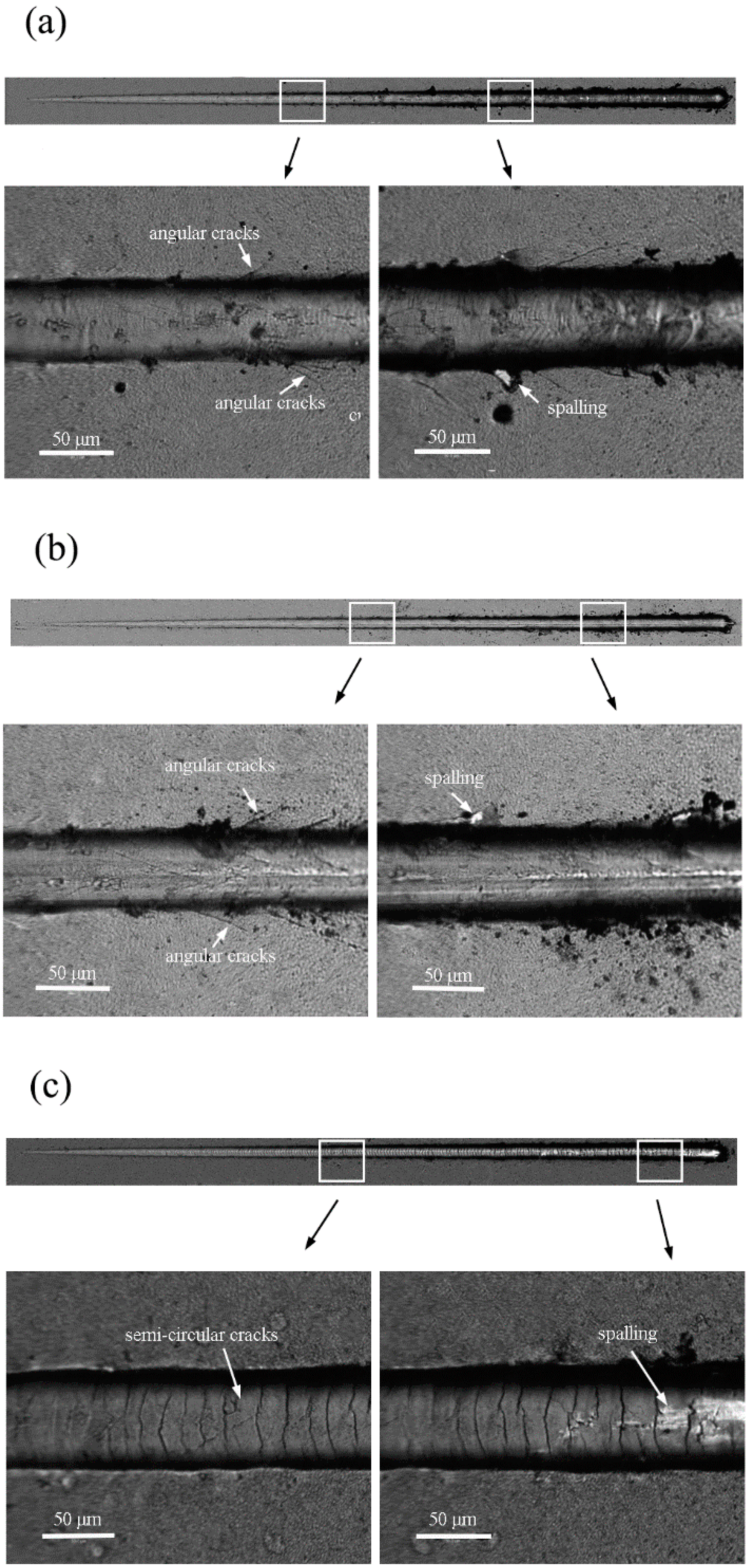
3.4. Adhesion
3.5. Corrosion Resistance
4. Conclusions
Author Contributions
Funding
Conflicts of Interest
References
- McGillivray, G.W.; Geeson, D.A.; Greenwood, R.C. Studies of the kinetics and mechanism of the oxidation of uranium by dry and moist air A model for determining the oxidation rate over a wide range of temperatures and water vapor pressures. J. Nucl. Mater. 1994, 208, 81–97. [Google Scholar] [CrossRef]
- Toque, C.; Milodowski, A.E.; Baker, A.C. The corrosion of depleted uranium in terrestrial and marine environments. J. Environ. Radioact. 2014, 128, 97–105. [Google Scholar] [CrossRef] [PubMed]
- Orman, S.; Owen, L.W.; Picton, G. The corrosion behaviour of nickel-plated uranium. Corros. Sci. 1972, 12, 35–44. [Google Scholar] [CrossRef]
- Liu, K.Z.; Luo, L.Z.; Zhou, W. Study of behaviors of aluminum overlayers deposited on uranium via aes, eels, and xps. Appl. Surf. Sci. 2013, 270, 184–189. [Google Scholar] [CrossRef]
- Liu, T.W.; Dong, C.; Wu, S. TiN, TiN gradient and Ti/TiN multi-layer protective coatings on Uranium. Surf. Coat. Technol. 2007, 201, 6737–6741. [Google Scholar] [CrossRef]
- Zhu, S.F.; Chen, L.; Wu, Y.P. Microstructure and corrosion resistance of Cr/Cr2N multilayer film deposited on the surface of depleted uranium. Corros. Sci. 2014, 82, 420–425. [Google Scholar] [CrossRef]
- Arkush, R.; Mintz, M.H.; Shamir, N. Passivation of uranium towards air corrosion by N2+ and C+ ion implantation. J. Nucl. Mater. 2000, 281, 182–190. [Google Scholar] [CrossRef]
- Arkush, R.; Mintz, M.H.; Shamir, N. Long-term amorphisation of C+ and N2+ implanted layers on a uranium surface. J. Alloys Compd. 2002, 330, 472–475. [Google Scholar] [CrossRef]
- Wang, Y.T.; Lin, Y.C. Study on the Performance of Nano-Titanium Nitride-Coated Stainless Steel Electrodes in Electro-Fenton Systems. Nanomaterials 2018, 8, 494. [Google Scholar] [CrossRef] [PubMed]
- Mori, T.; Fukuda, S.; Takemura, Y. Improvement of mechanical properties of Ti/TiN multilayer film deposited by sputtering. Surf. Coat. Technol. 2001, 140, 122–127. [Google Scholar] [CrossRef]
- Shukla, K.; Rane, R.; Alphonsa, J.; Maity, P.; Mukherjee, S. Structural, mechanical and corrosion resistance properties of Ti/TiN bilayers deposited by magnetron sputtering on AISI 316L. Surf. Coat. Technol. 2017, 324, 167–174. [Google Scholar] [CrossRef]
- Håkansson, G.; Hultman, L.; Sundgren, J.-E.; Greene, W.-D.; Munz, W.-D. Microstructures of TiN films grown by various physical vapour deposition techniques. Surf. Coat. Technol. 1991, 48, 51–67. [Google Scholar] [CrossRef]
- Al Jabbari, Y.S.; Fehrman, J.; Barnes, A.C.; Zapf, A.M.; Zinelis, S.; Berzins, D.W. Titanium Nitride and Nitrogen Ion Implanted Coated Dental Materials. Coatings 2012, 2, 160–178. [Google Scholar] [CrossRef] [Green Version]
- Perillo, P.M. Corrosion behaviour of titanium nitride coating on Titanium and Zircaloy-4. Am. J. Mater. Sci. Appl. 2015, 3, 18–25. [Google Scholar]
- Konstantinidis, S.; Ricard, A.; Ganciu, M. Measurement of ionic and neutral densities in amplified magnetron discharges by pulsed absorption spectroscopy. J. Appl. Phys. 2004, 95, 2900–2905. [Google Scholar] [CrossRef]
- Kouznetsov, V.; Macák, K.; Schneider, J.M. A novel pulsed magnetron sputter technique utilizing very high target power densities. Surf. Coat. Technol. 1999, 122, 290. [Google Scholar] [CrossRef]
- Ehiasarian, A.P.; Münza, W.-D.; Hultman, L.; Helmersson, U.; Petrov, I. High power pulsed magnetron sputtered CrNx films. Surf. Coat. Technol. 2003, 163–164, 267–272. [Google Scholar] [CrossRef]
- Barna, P.B.; Adamik, M. Fundamental structure forming phenomena of polycrystalline films and the structure zone models. Thin Solid Films 1998, 317, 27–33. [Google Scholar] [CrossRef]
- Sarakinos, K.; Alami, J.; Konstantinidis, S. High power pulsed magnetron sputtering a review on scientific and engineering. Surf. Coat. Technol. 2010, 204, 1661–1684. [Google Scholar] [CrossRef]
- Chawla, V.; Jayaganthan, R.; Chandra, R. Structural characterizations of magnetron sputtered nanocrystalline TiN thin films. Mater. Charact. 2008, 59, 1015–1020. [Google Scholar] [CrossRef]
- Abadias, G. Stress and preferred orientation in nitride-based pvd coatings. Surf. Coat. Technol. 2008, 202, 2223–2235. [Google Scholar] [CrossRef]
- Pelleg, J.; Zevin, L.Z.; Lungo, S. Reactive-sputter-deposition TiN films on glass substrates. Thin Solid Films 1991, 197, 117–128. [Google Scholar] [CrossRef]
- Greene, J.E.; Sundgren, J.; Hultman, L. Development of preferred orientation in polycrystalline TiN layers grown by ultra high vacuum reactive magnetron sputtering. Appl. Phys. Lett. 1995, 67, 2928–2930. [Google Scholar] [CrossRef]
- Paulitsch, J.; Mayrhofer, P.H.; Münz, W.D. Structure and mechanical properties of CrN/TiN multilayer coatings prepared by a combined HIPIMS/UBMS deposition technique. Thin Solid Films 2008, 517, 1239–1244. [Google Scholar] [CrossRef]
- Wu, J.; Wu, B.H.; Ma, D.L. Effects of magnetic field strength and deposition pressure on the properties of TiN films produced by high power pulsed magnetron sputtering (HPPMS). Surf. Coat. Technol. 2017, 315, 258–267. [Google Scholar] [CrossRef]
- Bull, S.J. Failure modes in scratch adhesion testing. Surf. Coat. Technol. 1991, 50, 25–32. [Google Scholar] [CrossRef]
- Gharagozloo, P.E.; Kanouff, M.P. Ionic diffusion oxidation model of uranium. J. Am. Ceram. Soc. 2013, 96, 2943–2949. [Google Scholar] [CrossRef]


| Deposition Mode | Distance to Targets (mm) | Ratio of Ar/N2 | Ti Inter-Layer | TiN Film | Deposition Rate (nm/min) | ||
|---|---|---|---|---|---|---|---|
| Time (min) | Deposition Mode | Time (min) | Deposition Mode | ||||
| 1 | 150 | 160/18 | 5 | DCMS | 35 | DCMS | 62 |
| 2 | 150 | 160/18 | 5 | HPPMS | 35 | DCMS | 67 |
| 3 | 150 | 160/18 | 5 | HPPMS | 70 | HPPMS | 28 |
| Tribology Pair | Load (g) | Speed (r/min) | Radius of Balls (mm) |
|---|---|---|---|
| Ф6 mm SiN | 100 | 160 | 4 |
| Deposition Mode | DCMS | HP + DC | HPPMS |
|---|---|---|---|
| Ra (nm) | 46.65 ± 11.27 | 37.14 ± 6.65 | 25.89 ± 5.29 |
| Hardness (GPa) | 15.75 ± 0.41 | 20.56 ± 0.76 | 22.09 ± 0.39 |
| Modulus (GPa) | 163.62 ± 2.21 | 200.37 ± 4.17 | 220.21 ± 2.33 |
| Deposition mode | 1 | 2 | 3 |
| Average tribology coefficient | 0.56 | 0.42 | 0.34 |
| Deposition Mode | Ecorr (mV) | Icorr (A/cm2) |
|---|---|---|
| DU | −773 ± 97 | 3.4 ± 0.7 × 10⁻⁶ |
| DCMS | −230 ± 21 | 5.1 ± 3.8 × 10⁻⁷ |
| HP + DC | −113 ± 14 | 2.7 ± 1.4 × 10⁻⁷ |
| HPPMS | −87 ± 19 | 2.6 ± 1.1 × 10⁻⁸ |
© 2018 by the authors. Licensee MDPI, Basel, Switzerland. This article is an open access article distributed under the terms and conditions of the Creative Commons Attribution (CC BY) license (http://creativecommons.org/licenses/by/4.0/).
Share and Cite
Ding, J.; Yin, X.; Fang, L.; Meng, X.; Yin, A. TiN Films Deposited on Uranium by High Power Pulsed Magnetron Sputtering under Low Temperature. Materials 2018, 11, 1400. https://doi.org/10.3390/ma11081400
Ding J, Yin X, Fang L, Meng X, Yin A. TiN Films Deposited on Uranium by High Power Pulsed Magnetron Sputtering under Low Temperature. Materials. 2018; 11(8):1400. https://doi.org/10.3390/ma11081400
Chicago/Turabian StyleDing, Jingjing, Xixi Yin, Liping Fang, Xiandong Meng, and Anyi Yin. 2018. "TiN Films Deposited on Uranium by High Power Pulsed Magnetron Sputtering under Low Temperature" Materials 11, no. 8: 1400. https://doi.org/10.3390/ma11081400
APA StyleDing, J., Yin, X., Fang, L., Meng, X., & Yin, A. (2018). TiN Films Deposited on Uranium by High Power Pulsed Magnetron Sputtering under Low Temperature. Materials, 11(8), 1400. https://doi.org/10.3390/ma11081400