Insertion of Platinum Nanoparticles into MoS2 Nanoflakes for Enhanced Hydrogen Evolution Reaction
by
 , and
, and
Dan Li
1,2, 
Yang Li
1,
Bowei Zhang
2,
Yu Hui Lui
2,
Sivaprasad Mooni
1,3,
Rongsheng Chen
4,
Shan Hu
2,* and
Hongwei Ni
1,* 1
The State Key Laboratory of Refractories and Metallurgy, Key Laboratory for Ferrous Metallurgy and Resources Utilization of Ministry of Education, Wuhan University of Science and Technology, Wuhan 430081, China
2
Department of Mechanical Engineering, Iowa State University, Ames, IA 50011, USA
3
Electroanalytical Lab., Department of Chemistry, Sri Venkateswara University, Tirupati 517502, India
4
School of Chemical Engineering and Technology, Wuhan University of Science and Technology, Wuhan 430081, China
*
Authors to whom correspondence should be addressed.
Materials 2018, 11(9), 1520; https://doi.org/10.3390/ma11091520
Submission received: 10 July 2018
/
Revised: 13 August 2018
/
Accepted: 22 August 2018
/
Published: 24 August 2018
(This article belongs to the Special Issue Metal-based Heterogeneous Catalysts for Hydrogen Generation/Production)
Abstract
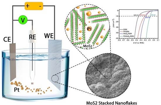
:Pt as a chemical inert metal has been widely applied as the counter electrode in various electrochemical measurements. However, it can also be dissolved and redeposit to the working electrode under certain electrochemical circumstances. Herein we demonstrated a cyclic voltammetry (CV) cycling method to synthesize a catalyst comprising inserted Pt nanoparticles into MoS2 nanoflake stack structures on stainless steel mesh (SSM). The binder-free composite structure exhibits significantly enhanced hydrogen evolution reaction (HER) catalytic activity with an overpotentials of 87 mV at 10 mA cm−2. The deposited Pt nanoparticles significantly enhance the catalytic activity through changing the structure of MoS2 and increasing the amount of active sites. This work provides a new way forward for rational design of the nano-electrocatalysts.
1. Introduction
To address the environmental crisis of global warming and energy shortage, all kinds of renewable energies such as wind, water and solar energy have been regarded as promising substitutes for fossil energy [1,2,3,4]. Hydrogen gas (H2), with zero carbon emission and a high combustion value, has been considered to be a green and high energy source as it can be produced by electro-splitting of water, which can convert electric energy into chemical energy for easier storage and delivery [5]. Up to now, noble-metal platinum (Pt) based electrocatalysts remain as the benchmark for hydrogen evolution reaction (HER) owing to the low overpotential and small Tafel slope. Unfortunately, its widespread utilization have been greatly restricted by the skyrocketing prices. Therefore, to develop noble-metal-free HER catalysts with high catalytic efficiency, long-term durability and low cost, many metal and metallic compounds with various nanostructures have been exploited [6]. Transition metal composites [7,8], transition metal carbide [9,10], phosphides [11,12], and chalcogenides [13,14,15,16] have received extensive research interest.
Over the past decade, molybdenum disulfide (MoS2) has attracted a great amount of attention because of its extraordinary ability for accepting electrons and protons [13,15]. This material exhibits good corrosion resistance compared with other most Transition metal composites in acid solution and similar electronic properties with Pt-group metals [16,17]. What’s more, the hydrogen binding energy of MoS2 was calculated to be similar to that of Pt [18,19] and the reaction activity of MoS2 can be tuned by the density of exposed edge sites. The inert basal plane with limited amount of edge active sites greatly limits its catalytic activity. In recent years, some approaches such as chemical interlayer intercalation [14,20], 2H-to-1T phase conversion [15,21] and large surface structural design [22,23] have been reported as effective methods to reduce the HER overpotentials and Tafel slope of MoS2.
Pt metal has been prevalently used as a counter electrode in various electrochemical measurements due to its chemical inertness. However, Pt can also be oxidized and dissolved under certain chemical or electrochemical circumstances. The dissolution of Pt is most significant when highly oxidative potential is applied to the Pt counter electrode, while repetitive oxidation and reduction cycles further aggravate the dissolution of Pt [24,25]. Pt dissolution and redeposition are easier in acidic media than that in alkaline medium during electrochemical process [26]. In HER process, cyclic voltammetry (CV) scans are inevitably applied to pretreat the surface of electrocatalysts and stabilize the polarization curve. Therefore, without ion exchange membrane to separate the working electrode from the counter electrode, Pt counter electrode would be unavoidably dissolved and redeposited onto the working electrode and would affect the HER catalytic activity of the working electrode.
Herein, we demonstrate a facile and cost-effective route to grow MoS2 nanoflakes directly on the stainless steel mesh (SSM) substrates via a hydrothermal process. SSM is a widely used engineering product with a high physical durability and chemical resistance in both basic and acidic environments [27,28]. Additionally, it has a relatively low electrical resistivity of around 70 mΩ cm and the elements of Mo, Ni, Cr are also in favor of the HER activity. Then Pt plate was used as counter electrode to introduce Pt nanoparticles into MoS2 nanoflakes by multiple CV cycles in 0.5 mol L−1 H2SO4 aqueous solution. The resultant composite electrode is denoted as Pt-MoS2/SSM. The composite structure exhibits significantly enhanced intrinsic catalytic activity toward HER, compared with MoS2/SSM and Pt/SSM. The enhanced HER performance of Pt-MoS2/SSM is ascribed to the interaction of Pt and MoS2.
2. Materials and Methods
2.1. Materials and Chemicals
316L SSM (1 cm × 2.5 cm, 200 mesh) was purchased from good fellow (Cambridge, Ltd., Shanghai, China). Pt plate (0.6 cm × 0.2 cm), Na2MoO4·2H2O (99%), CH4N2S (99%), H2SO4 (95%), HCL (37%), ethanol were purchased from Sinopharm Chemical Reagent Co., Ltd., Shanghai, China. All chemicals were analytical grade and used as received without further purification. The deionized water (~18.2 mΩ.cm) used throughout all experiments was purified by Milli-Q system (Thermo Fisher Scientific, Massachusetts, MA, USA).
2.2. Synthesis of Pt-MoS2/SSM, MoS2/SSM and Pt/SSM
The SSM was carefully cleaned in ethanol, 20% HCl aqueous solution, and deionized water for 15 min with assistance of sonication to remove the impurities on the surface respectively. The MoS2/SSM was synthesized via a simple hydrothermal method. 0.19 g CH4N2S and 0.121 g Na2MoO4·2H2O were added to 30 mL of deionized water to form a homogeneous solution under vigorously stirring for 10 min. Then the cleaned SSM and solution were transferred into a 50 mL Teflon-lined stainless steel autoclave (Zhong Nuo Instrument Co., Ltd., Wuhan, China), sealed and maintained 220 °C for 24 h, then naturally cooling down to room temperature. Subsequently, the sample was taken out, rinsed in ethanol and deionized water respectively and dried at 50 °C for overnight. The MoS2/SSM was immersed in 20% H2SO4 solution for 10 min to pretreat the surface and then subjected to 200 CV cycles (150 mV s−1 between 0.4 and −1.0 V vs. SCE) using a graphite rod as a counter electrode to activate the electrode in the same electrolyte solution [13,29].
The Pt-MoS2/SSM was synthesized by a CV cycle method, which was carried out in a standard three-electrode cell containing 0.5 mol L−1 H2SO4 aqueous solution (pH = 0.03, 50 mL) at 20 °C using the activated MoS2/SSM, a Pt plate electrode, and a saturated calomel electrode (SCE) (Gaoss Union, Wuhan, China) as working, counter and reference electrodes, respectively. The CV experiment was performed with 200, 400, 600, 800 cycles between 0.6 and −1.2 V vs. SCE with a scan rate of 150 mV s−1. Subsequently, the electrodes were withdrawn from the solution, carefully rinsed with deionized water and dried at 50 °C. For comparative studies, Pt/SSM was synthesized via the same electrochemical method. The MoS2 and Pt loadings of Pt-MoS2/SSM were determined by inductively coupled plasma-optical emission spectrometry (ICP-OES, Optima 5300DV, Perkin Elmer, Richmond, California, CA, USA) to be ~0.14 mg cm−2 and ~0.13 mg cm−2, respectively. There is almost the same loading mass of MoS2 (0.14 mg cm−2) in MoS2/SSM and Pt (0.13 mg cm−2) in Pt/SSM electrode respectively according to the ICP-OES results.
2.3. Characterizations
The crystal phase analysis of the MoS2/SSM and Pt-MoS2/SSM electrocatalysts were performed by X-ray diffraction (XRD, XRD-7000S diffractometer, Shimadzu, Kyoto, Japan) using Cu Kα radiation at a scanning rate of 5° min−1 in the 2θ range from 10 to 80°. The morphology and structure of the samples were characterized using scanning electron microscopy (SEM, Hitachi S-4800 high-resolution scanning electron microscope, Kyoto, Japan) at an accelerating voltage of 15 kV and transmission electron microscopy (TEM, Hitachi H-7600 transmission electron microscope, Kyoto, Japan). The elemental composition of the Pt-MoS2 supported by SSM and the valence states of the metal elements were probed by an X-ray photoelectron spectroscopy (XPS, Thermo ESCALAB 250XI, Massachusetts, MA, USA). The Faradic efficiency of the electrocatalysts was determined by analyzing H2 produced at a current density of 50 mA cm−2. The gaseous products were detected using a GC-7920 Gas Chromatograph (Beijing Zhong Jiao Jin Yuan Technology Co., Ltd., Beijing, China) equipped with a TCD detector (N2 as carrier gas).
2.4. Electrochemical Measurements
All electrochemical measurements were conducted at room temperature with a CHI 660E electrochemical workstation (CH Instrument Co., Ltd., Shanghai, China) in a typical three-electrode system. The SSM loaded with MoS2, Pt, and Pt-MoS2 were directly used as working electrode, a graphite rod as counter electrode, and SCE as reference electrode. The electrolyte solutions were 0.5 mol L−1 H2SO4 aqueous solution and all the potentials reported in this paper were calibrated with the reversible hydrogen electrode (RHE) according to the equation: ERHE = ESCE + 0.2412 + 0.05916 × pH. All the polarization curves were measured at 5 mV s−1 by linear sweep voltammetry (LSV). The long-term stability tests were carried out by the chronopotentiometry in same conditions. There were IR compensations and no stirring in all measurements.
2.5. Calculation of TOFs for HER
The turnover frequency (TOF, s−1) for HER was calculated by following equation:
where j is the current density (A cm−2) obtained at overpotential of 150 mV, A is the surface area of the electrode, F is the Faraday efficiency (96,485 C mol−1) and m is the number of catalyst active sites (in mol) based on the calculation in one CV cycle (from previous report [30]). The factor 1/2 is included considering that two electrons are required to form one hydrogen molecule from two protons.
3. Results
The HER polarization curves of Pt-MoS2/SSM fabricated by 200, 400, 600, 800 CV cycles with Pt as counter electrode were shown in Figure 1a. The polarization curve of MoS2/SSM (denoted as “0 cycle” in Figure 1a) is also included for comparison. The polarization curves changed remarkably when the CV cycles increased from 0 to 600 cycles. After 600 cycles, the catalytic performance became stable. The HER overpotentials at jHER = 100 mA cm−2 as a function of cycle number used in the Pt-MoS2/SSM synthesis process is shown in Figure 1b. The enhancement of the HER activity should be attributed to the trace dissolved Pt species from the counter electrode and redeposition on the working electrode. To probe the formation process of Pt in MoS2/SSM, we used the same Pt plate as a working electrode to do the redox process in 0.5 mol L−1 H2SO4 aqueous solution with the scan rate of 150 mV s−1. As shown in Figure 1c, the representative peaks at 0.39 and 0.57 V vs. SCE should be ascribed to the formation/reduction of Pt oxide, respectively. Other peaks under larger potentials are rooted in electro adsorption/desorption of ‘O’ and oxygen evolution reaction (OER) according to the previous report [26]. By contrast, if a graphite rod was employed as the counter electrode during the Pt-MoS2/SSM synthesis process, the HER polarization curves remained stable even after 800 CV cycles, as shown in Figure 1d.
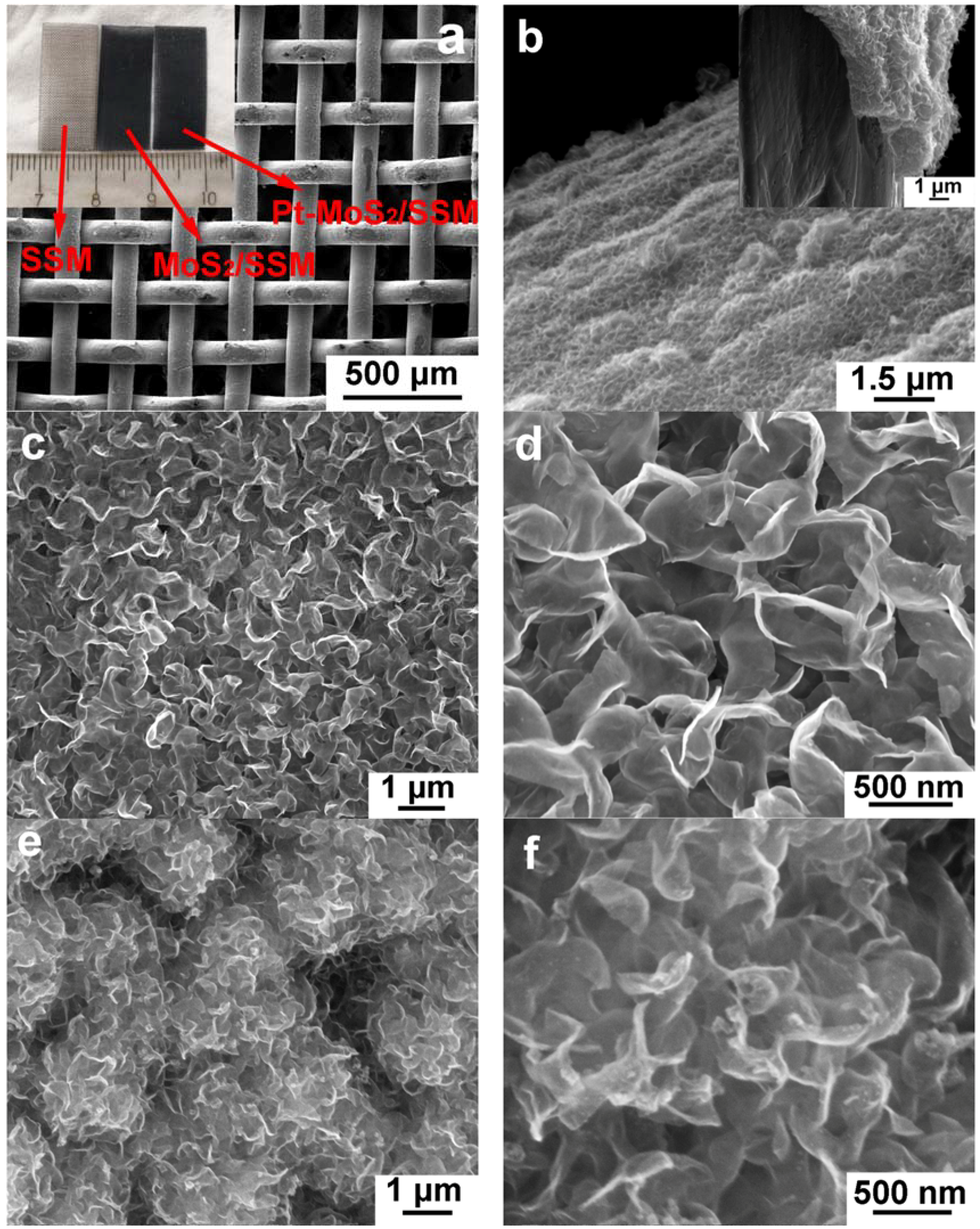
The morphology of the as prepared MoS2/SSM was investigated by SEM, as shown in Figure 2. It is clearly observed that the SSM structure integrity is mostly retained after hydrothermal and electrochemical treatment (Figure 2a). The SSM color changed from silvery white to dark grey after hydrothermal treatment, with almost no further change after CV process, as shown in inset Figure 2a. The side view of high magnifications of the SSM was displayed in Figure 2b, suggesting that the MoS2 nanoflakes was successfully deposited on SSM with the thickness of ~1.5 μm. Figure 2c,d showed the high resolution SEM images of MoS2/SSM with nanoflakes of size between 300 to 800 nm. Figure 2e,f showed the high resolution SEM images of Pt-MoS2/SSM had similar morphology as MoS2/SSM. In both MoS2/SSM and Pt-MoS2/SSM, interconnected nanoflake stack structures were observed, which can provide abundant electrolyte channels for short ion diffusion/exchange paths and greatly enhance the active surface area for electrochemical reactions. It should be noticed that under the current magnification, no Pt nanoparticles were observed in the SEM of Pt-MoS2/SSM samples. The existence of Pt nanoparticles will be proven by the TEM studies discussed later.
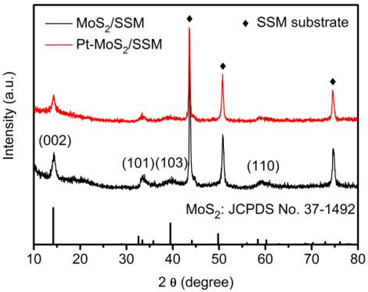
Figure 3 shows XRD pattern of the MoS2 nanoflakes (black) and Pt-MoS2 composites (red) supported by SSM substrate (marked in rhombus). The diffraction peaks at 14.4°, 33.5°, 39.5° and 58.3° should be assigned to MoS2 (JCPDS No. 37-1492) after hydrothermal process [28]. The broadening of the (101), (103) and (110) peaks indicates that the lattice imperfections in the crystal structure. There are no peaks corresponding to metallic molybdenum or molybdenum oxides. Meanwhile, after the CV process, the characteristic peaks of Pt-MoS2 are observed with no obvious shift but a slight decrease in the intensity for the typical basal (002) planes of MoS2, implying the increase of interplanar spacing could happen after Pt nanoparticles insertion or CV process [20,29,31,32]. However, no signal of Pt is observed, which is attributed to the low mass ratio of Pt in the nanocomposite.
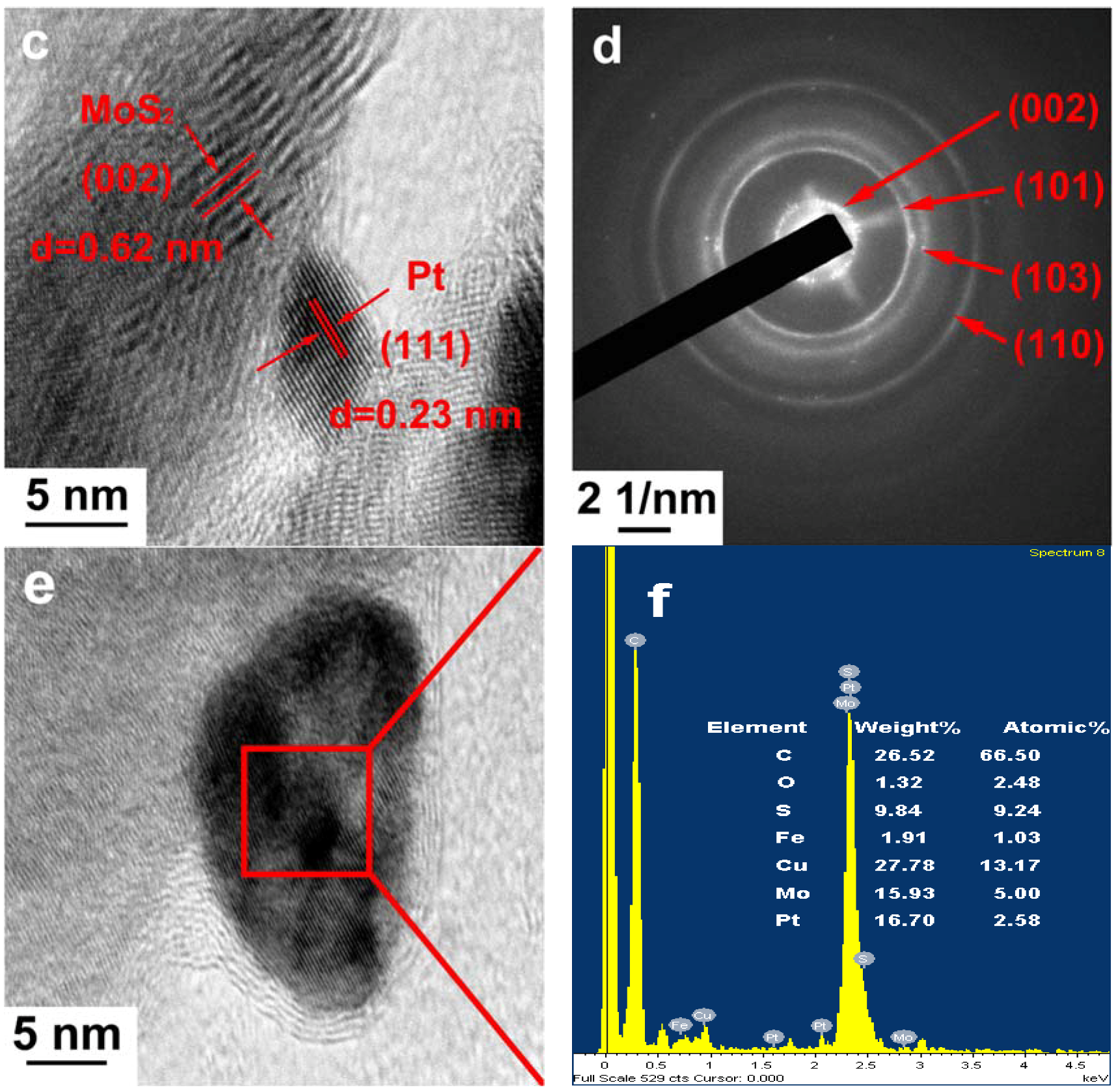
In order to further elucidate the structure of the as prepared electrode, TEM and EDX (Energy Dispersive X-ray Spectroscopy) were conducted for Pt-MoS2 are shown in Figure 4. TEM image in Figure 4a shows the morphology of MoS2 layer, confirming that the thin nanoflakes structure of MoS2 with thickness of ~20 nm has been successfully synthesized. Obviously, Pt nanoparticles with a relatively deep color are distributed in the MoS2 layer with diameters between 3 nm and 15 nm, as shown in Figure 4. The high-resolution TEM images of Pt-MoS2 are illustrated in Figure 4b,c. The interplanar spacing of 0.62 nm and 0.26 nm should be assigned to the typical (002) and (101) lattice plane of MoS2, respectively. Moreover, the adjacent lattices spacing is 0.23 nm in Figure 4c, which is well in agreement with the (111) plane of Pt. As displayed in Figure 4d, the selected-area diffraction (SAED) pattern for Pt-MoS2 further indicates that the diffraction ring is well indexed to MoS2. Figure 4e shows the boundary details between Pt nanoparticle and MoS2. Combining with the TEM-EDX image of Pt nanoparticle showed in Figure 4f, all the results suggest that the successfully insertion of Pt species into MoS2 stacked structures.
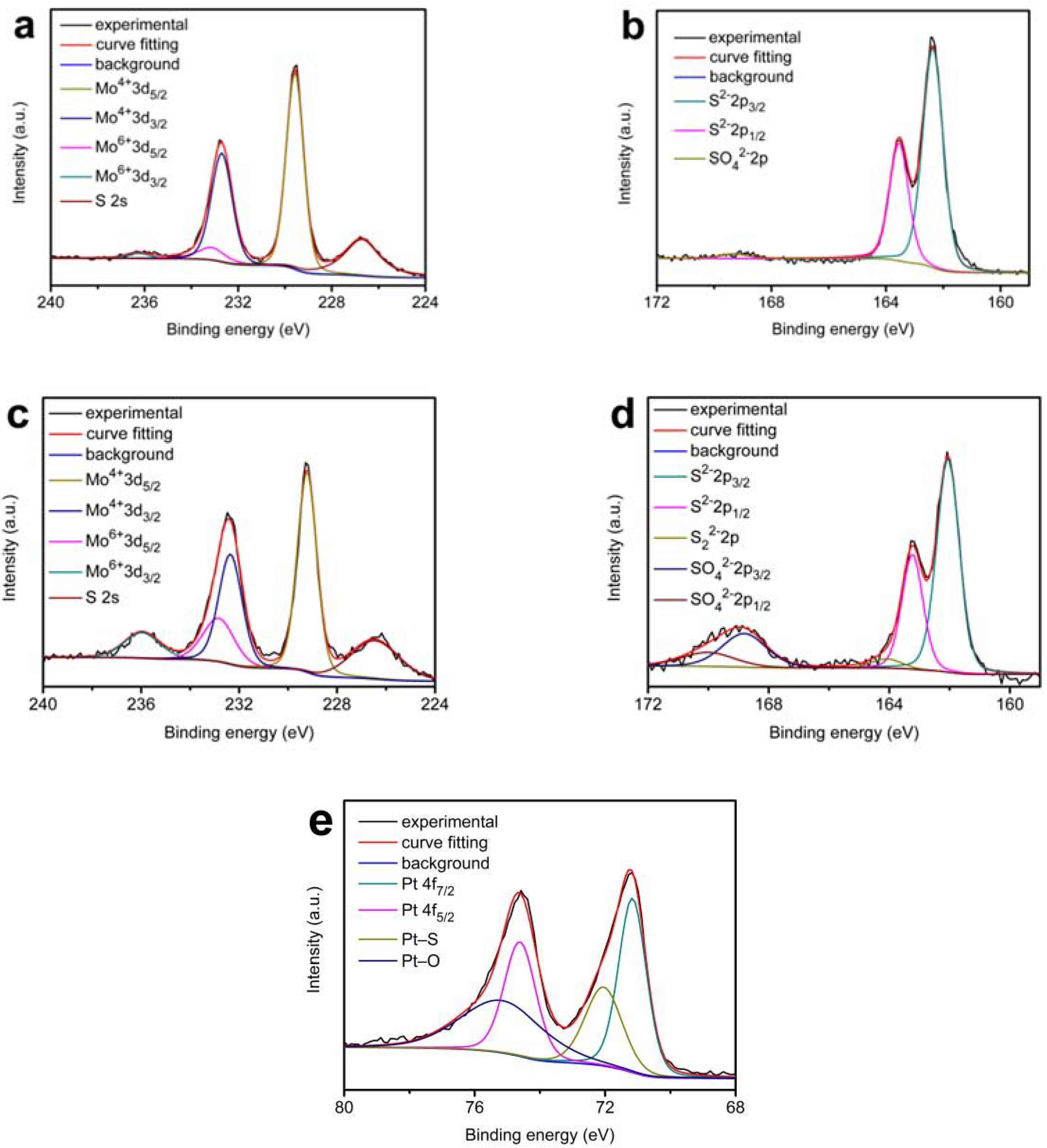
XPS experiments were carried out to further determine the chemical state of MoS2/SSM and Pt-MoS2/SSM catalysts. Figure 5a,b display the XPS spectra of Mo are 3d and S 2p of the MoS2/SSM. In the molybdenum spectrum of MoS2/SSM, two peaks are observed at approximately 229.6 eV and 232.7 eV, which can be attributed to typical Mo 3d5/2 and Mo 3d3/2 binding energies of Mo4+ oxidation state in all the materials respectively [15,20,29,32]. The peaks at 226.7 eV are indexed to S 2s [16]. Note that the presence of a shoulder in the Mo 3d3/2 peak indicates the Mo4+ ions are mixed with a few Mo6+ ions, which should be attributed to the surface oxidation of MoS2 in the air [15,32],. Meanwhile, the corresponding S 2p peaks were deconvoluted by fitting the data with the S 2p3/2 and S 2p1/2 at 162.4 eV and 163.5 eV suitably in Figure 5b. An extremely weak peak of the SO42− observed at 169.3 eV is due to the oxidation in the air.
Compared with the MoS2/SSM, significant changes in both Mo and S spectra are observed owing to the insertion of platinum for Pt-MoS2/SSM. There are four peaks in the Mo 3d spectrum of Pt-MoS2/SSM in Figure 5c. Except the S 2p peaks at 226.4 eV, other peaks are ascribed to an overlap of two doublets of Mo4+ ions and Mo6+ ions 3d peaks. The ratio of Mo6+ to Mo4+ for Pt-MoS2/SSM is evaluated to be ~0.55 by taking a ratio of the intensities of the deconvoluted peaks. As compared to the ratio of Mo6+ to Mo4+ of ~0.10 for MoS2/SSM, it indicates that the structure of MoS2 has been changed and there are some platinum atoms incorporated into the MoS2 catalyst. The presence of a shoulder in the S 2p1/2 peak in Figure 5d reveals presence of a small amount of S22−, which is a major active edge site of MoS2 [29,33,34,35,36]. Furthermore, the peak of SO42− markedly increases with the insertion of platinum, which likely be attributed to the accumulation of sulfur oxidation during CV process, agreeing with those in previous reports [32,37,38]. From the high resolution Pt 4f XPS peaks shown in Figure 5e, characteristic peaks of Pt 4f7/2, Pt 4f5/2 at 71.2 eV and 74.6 eV, respectively, should be attributed to metallic Pt nanoparticles. The Pt 4f peak shows two shoulders on the high binding energy side of the Pt 4f5/2 and Pt 4f7/2 peaks at a binding energy of 75.2 eV and 72.1 eV, which can be assigned to the Pt atoms linked to the oxygen and sulfur atoms respectively [39,40]. The formation of Pt–S bond can cause sulfur vacancies, and then enhance the catalytic activity of MoS2 inner planes [29,41,42].
The HER catalytic activities of the Pt-MoS2/SSM electrode have been further characterized with a three electrode electrochemical system in 0.5 mol L−1 H2SO4 aqueous solution by linear sweep voltammetry (LSV). Figure 6a shows the polarization curve of the as-obtained composite electrodes at a scan rate of 5 mV s−1. The as-prepared electrodes of MoS2/SSM and Pt/SSM exhibit overpotentials of 183 mV and 210 mV, respectively at a current density of 10 mA cm−2. The Pt-MoS2/SSM shows much improved HER activity of overpotentials of 87 mV to achieve the same current density. Moreover, the overpotential values are 515 mV for SSM, 434 mV for Pt/SSM, 379 mV for MoS2/SSM, and 225 mV for Pt-MoS2/SSM, at the current density of 100 mA cm−2. The corresponding Tafel plots of the four electrodes are displayed in Figure 6b. As expected, the Tafel slope of Pt-MoS2/SSM electrode is only 42.7 mV dec−1, which is much lower than those of the MoS2/SSM (108.6 mV dec−1), Pt/SSM (127.1 mV dec−1), and SSM (220.4 mV dec−1) electrodes, suggesting fast kinetics of the Pt-MoS2/SSM electrode. In addition, the turnover frequency value of the Pt-MoS2/SSM was calculated to be 0.27 s−1 at an overpotential of 150 mV, which is higher than that of the MoS2/SSM (0.08 s−1) and Pt/SSM (0.05 s−1). The mass-specific activities of MoS2 (jmass) in MoS2/SSM and Pt-MoS2/SSM samples can be calculated by the following equation [25]:
Based on the equation, the jmass at different potentials was be calculated. As shown in the Figure 6c, the jmass of Pt-MoS2 is higher than the value of MoS2 for all potentials, indicating the MoS2 mass activities were increased after Pt was introduced. According to these results, it is reasonable to believe that the increased activity of HER should be attributed to the change of the MoS2 structure with insertion of platinum and a strong synergistic effect between Pt nanoparticles and the MoS2 nanoflakes.
The durability of the Pt-MoS2/SSM electrode is evaluated in long-term bulk electrolysis via chronoamperometry. As seen from Figure 6d, the catalytic electrode shows almost a horizontal curve at a current density of 100 mA cm−2 in 0.5 M H2SO4 aqueous solution. There is only a small increasement in potential of 32 mV at the current density of 100 mA cm−2 for 15 h, suggesting the high stability of Pt-MoS2/SSM electrode. The insert image in Figure 6d shows the theoretically calculated gas amount equals well to the experimentally measured values, suggesting that the Faradic efficiency of Pt-MoS2 electrocatalyst was about 100%.
4. Conclusions
In conclusion, using a simple CV cycling process, we have successfully synthesized Pt-MoS2/SSM catalyst, which comprises of Pt nanoparticles inserted into the stacked structures of MoS2 supported by SSM. The binder-free Pt-MoS2/SSM electrode can be directly used as a catalytic electrode for HER. Compared to SSM, Pt/SSM and MoS2/SSM, Pt-MoS2/SSM exhibits much higher electrocatalytic activity for HER. It exhibits a very low over potentials of 87 and 225 mV for current density of 10 and 100 mA cm−2, respectively, and a good durability in acid. The MoS2 in Pt-MoS2/SSM also has higher mass-specific catalytic activity than that in MoS2/SSM. The superior performances of Pt-MoS2/SSM are mainly ascribed to its unique nanostructure and the synergistic effect between the nanoparticles and the MoS2 nanoflakes. This work provides a promising approach for synthesizing advanced catalysts for energy conversion and storage applications.
Author Contributions
Methodology, D.L.; Software, Y.H.L.; Validation, Y.L. and R.C.; Formal Analysis, D.L. and Y.L.; Investigation, D.L.; Resources, H.N.; Writing—Original Draft Preparation, D.L.; Writing—Review & Editing, B.Z., S.M., R.C. and S.H.; Funding Acquisition, H.N.
Funding
This research was funded by [National Natural Science Foundation of China] grant number [51471122 and 51604202] and [Key Program of Natural Science Foundation of Hubei Province of China] grant number [2015CFA128].
Conflicts of Interest
The authors declare no conflict of interest.
References
- Luo, J.; Im, J.H.; Mayer, M.T.; Schreier, M.; Nazeeruddin, M.K.; Park, N.G.; Tilley, S.D.; Fan, H.J.; Grätzel, M. Water photolysis at 12.3% efficiency via perovskite photovoltaics and Earth-abundant catalysts. Science 2014, 345, 1593–1596. [Google Scholar] [CrossRef] [PubMed]
- Dresselhaus, M.S.; Thomas, I. Alternative energy technologies. Nature 2001, 414, 332–337. [Google Scholar] [CrossRef] [PubMed]
- Meskani, A.; Haddi, A.; Becherif, M. Modeling and simulation of a hybrid energy source based on solar energy and battery. Int. J. Hydrog. Energy 2015, 40, 13702–13707. [Google Scholar] [CrossRef]
- Chu, S.; Majumdar, A. Opportunities and challenges for a sustainable energy future. Nature 2012, 488, 294–303. [Google Scholar] [CrossRef] [PubMed]
- Turner, J.A. Sustainable Hydrogen production processes. Science 2017, 305, 972–975. [Google Scholar] [CrossRef] [PubMed]
- Li, X.; Hao, X.; Abudula, A.; Guan, G. Nanostructured catalysts for electrochemical water splitting: Current state and prospects. J. Mater. Chem. A 2016, 4, 11973–12000. [Google Scholar] [CrossRef]
- Deng, J.; Ren, P.; Deng, D.; Yu, L.; Yang, F.; Bao, X. Highly active and durable non-precious-metal catalysts encapsulated in carbon nanotubes for hydrogen evolution reaction. Energy Environ. Sci. 2014, 7, 1919–1923. [Google Scholar] [CrossRef]
- Xiao, C.; Li, Y.; Lu, X.; Zhao, C. Bifunctional porous NiFe/NiCo2O4/Ni foam electrodes with triple hierarchy and double synergies for efficient whole cell water splitting. Adv. Funct. Mater. 2016, 26, 3515–3523. [Google Scholar] [CrossRef]
- Wu, C.; Li, J. Unique Hierarchical Mo2C/C nanosheet hybrids as active electrocatalyst for hydrogen evolution reaction. ACS Appl. Mater. Interfaces 2017, 9, 41314–41322. [Google Scholar] [CrossRef] [PubMed]
- Gao, G.; O’Mullane, A.P.; Du, A. 2D MXenes: A new family of promising catalysts for the hydrogen evolution reaction. ACS Catal. 2017, 7, 494–500. [Google Scholar] [CrossRef]
- Li, W.; Xiong, D.; Gao, X.; Song, W.G.; Xia, F.; Liu, L. Self-supported Co–Ni-–P ternary nanowire electrodes for highly efficient and stable electrocatalytic hydrogen evolution in acidic solution. Catal. Today 2017, 287, 122–129. [Google Scholar] [CrossRef]
- Zhang, C.; Huang, Y.; Yu, Y.; Zhang, J.; Zhuo, S.; Zhang, B. Sub-1.1 nm ultrathin porous CoP nanosheets with dominant reactive {200} facets: A high mass activity and efficient electrocatalyst for the hydrogen evolution reaction. Chem. Sci. 2017, 8, 2769–2775. [Google Scholar] [CrossRef] [PubMed]
- Tsai, C.; Li, H.; Park, S.; Park, J.; Han, H.S.; Nørskov, J.K.; Zheng, X.; Abild-Pedersen, F. Electrochemical generation of sulfur vacancies in the basal plane of MoS2 for hydrogen evolution. Nat. Commun. 2017, 8, 1–8. [Google Scholar] [CrossRef] [PubMed]
- Ma, Q.; Hu, C.; Liu, K.; Hung, S.F.; Ou, D.; Chen, H.M.; Fu, G.; Zheng, N. Identifying the electrocatalytic sites of nickel disulfide in alkaline hydrogen evolution reaction. Nano Energy 2017, 41, 148–153. [Google Scholar] [CrossRef]
- Yang, Y.; Zhang, K.; Lin, H.; Li, X.; Chan, H.C.; Yang, L.; Gao, Q. MoS2–Ni3S2 heteronanorods as efficient and stable bifunctional electrocatalysts for overall water splitting. ACS Catal. 2017, 7, 2357–2366. [Google Scholar] [CrossRef]
- Ho, T.A.; Bae, C.; Lee, S.; Kim, M.; Montero-Moreno, J.M.; Park, J.H.; Shin, H. Edge-on MoS2 thin films by atomic layer deposition for understanding the interplay between the active area and hydrogen evolution reaction. Chem. Mater. 2017, 29, 7604–7614. [Google Scholar] [CrossRef]
- Velický, M.; Bissett, M.A.; Toth, P.S.; Patten, H.V.; Worrall, S.D.; Rodgers, A.N.J.; Hill, E.W.; Kinloch, I.A.; Novoselov, K.S.; Georgiou, T.; et al. Electron transfer kinetics on natural crystals of MoS2 and graphite. Phys. Chem. Chem. Phys. 2015, 17, 17844–17853. [Google Scholar] [CrossRef] [PubMed]
- Hinnemann, B.; Moses, P.G.; Bonde, J.; Jørgensen, K.P.; Nielsen, J.H.; Horch, S.; Chorkendorff, I.; Nørskov, J.K. Biomimetic hydrogen evolution: MoS2 nanoparticles as catalyst for hydrogen evolution. J. Am. Chem. Soc. 2005, 127, 5308–5309. [Google Scholar] [CrossRef] [PubMed]
- Laursen, A.B.; Kegnæs, S.; Dahl, S.; Chorkendorff, I. Molybdenum sulfides—Efficient and viable materials for electro—And photoelectrocatalytic hydrogen evolution. Energy Environ. Sci. 2012, 5, 5577–5591. [Google Scholar] [CrossRef]
- Chen, Z.; Leng, K.; Zhao, X.; Malkhandi, S.; Tang, W.; Tian, B.; Dong, L.; Zheng, L.; Lin, M.; Yeo, B.S.; et al. Interface confined hydrogen evolution reaction in zero valent metal nanoparticles-intercalated molybdenum disulfide. Nat. Commun. 2017, 8, 14548. [Google Scholar] [CrossRef] [PubMed] [Green Version]
- Hwang, D.Y.; Choi, K.H.; Park, J.E.; Suh, D.H. Highly efficient hydrogen evolution reaction by strain and phase engineering in composites of Pt and MoS2 nano-scrolls. Phys. Chem. Chem. Phys. 2017, 19, 18356–18365. [Google Scholar] [CrossRef] [PubMed]
- Vikraman, D.; Akbar, K.; Hussain, S.; Yoo, G.; Jang, J.Y.; Chun, S.H.; Jung, J.; Park, H.J. Direct synthesis of thickness-tunable MoS2 quantum dot thin layers: Optical, structural and electrical properties and their application to hydrogen evolution. Nano Energy 2017, 35, 101–114. [Google Scholar] [CrossRef]
- Sun, Z.; Fan, W.; Liu, T. Graphene/graphene nanoribbon aerogels as tunable three-dimensional framework for efficient hydrogen evolution reaction. Electrochim. Acta 2017, 250, 91–98. [Google Scholar] [CrossRef]
- Tavakkoli, M.; Holmberg, N.; Kronberg, R.; Jiang, H.; Sainio, J.; Kauppinen, E.I.; Kallio, T.; Laasonen, K. Electrochemical activation of single-walled carbon nanotubes with pseudo-atomic-scale platinum for the hydrogen evolution reaction. ACS Catal. 2017, 7, 3121–3130. [Google Scholar] [CrossRef]
- Zhang, L.; Han, L.; Liu, H.; Liu, X.; Luo, J. Potential-cycling synthesis of single platinum atoms for efficient hydrogen evolution in neutral media. Angew. Chem. Int. Ed. 2017, 56, 13694–13698. [Google Scholar] [CrossRef] [PubMed]
- Chen, R.; Yang, C.; Cai, W.; Wang, H.-Y.; Miao, J.; Zhang, L.; Chen, S.; Liu, B. Use of platinum as the counter electrode to study the activity of nonprecious metal catalysts for the hydrogen evolution reaction. ACS Energy Lett. 2017, 2, 1070–1075. [Google Scholar] [CrossRef]
- McArthur, M.A.; Jorge, L.; Coulombe, S.; Omanovic, S. Synthesis and characterization of 3D Ni nanoparticle/carbon nanotube cathodes for hydrogen evolution in alkaline electrolyte. J. Power Sources 2014, 266, 365–373. [Google Scholar] [CrossRef]
- Chen, J.S.; Ren, J.; Shalom, M.; Fellinger, T.; Antonietti, M. Stainless steel mesh-supported NiS nanosheet array as highly efficient catalyst for oxygen evolution reaction. ACS Appl. Mater. Interfaces 2016, 8, 5509–5516. [Google Scholar] [CrossRef] [PubMed]
- Li, G.; Zhang, D.; Yu, Y.; Huang, S.; Yang, W.; Cao, L. Activating MoS2 for pH-universal hydrogen evolution catalysis. J. Am. Chem. Soc. 2017. [Google Scholar] [CrossRef] [PubMed]
- Merki, D.; Fierro, S.; Vrubel, H.; Hu, X. Amorphous molybdenum sulfide films as catalysts for electrochemical hydrogen production in water. Chem. Sci. 2011, 2, 1262–1267. [Google Scholar] [CrossRef] [Green Version]
- Khan, M.; Yousaf, A.B.; Chen, M.; Wei, C.; Wu, X.; Huang, N.; Qi, Z.; Li, L. Molybdenum sulfide/graphene-carbon nanotube nanocomposite material for electrocatalytic applications in hydrogen evolution reactions. Nano Res. 2016, 9, 837–848. [Google Scholar] [CrossRef]
- Bose, R.; Jin, Z.; Shin, S.; Kim, S.; Lee, S.; Min, Y.S. Co-catalytic effects of CoS2 on the activity of the MoS2 catalyst for electrochemical hydrogen evolution. Langmuir 2017, 33, 5628–5635. [Google Scholar] [CrossRef] [PubMed]
- Li, G.; Zhang, D.; Qiao, Q.; Yu, Y.; Peterson, D.; Zafar, A.; Kumar, R.; Curtarolo, S.; Hunte, F.; Shannon, S.; et al. All the catalytic active sites of MoS2 for hydrogen evolution. J. Am. Chem. Soc. 2016, 138, 16632–16638. [Google Scholar] [CrossRef] [PubMed]
- Li, D.J.; Maiti, U.N.; Lim, J.; Choi, D.S.; Lee, W.J.; Oh, Y.; Lee, G.Y.; Kim, S.O. Molybdenum sulfide/N-doped CNT forest hybrid catalysts for high-performance hydrogen evolution reaction. Nano Lett. 2014, 14, 1228–1233. [Google Scholar] [CrossRef] [PubMed]
- Chang, Y.H.; Lin, C.T.; Chen, T.Y.; Hsu, C.L.; Lee, Y.H.; Zhang, W.; Wei, K.H.; Li, L.J. Highly efficient electrocatalytic hydrogen production by MoSx grown on graphene-protected 3D Ni foams. Adv. Mater. 2013, 25, 756–760. [Google Scholar] [CrossRef] [PubMed]
- Kibsgaard, J.; Jaramillo, T.F.; Besenbacher, F. Building an appropriate active-site motif into a hydrogen-evolution catalyst with thiomolybdate [Mo3S13]2− clusters. Nat. Chem. 2014, 6, 248–253. [Google Scholar] [CrossRef] [PubMed]
- Siriwardane, R.V.; Cook, J.M. Interactions of SO2 with sodium deposited on CaO. J. Colloid Interface Sci. 1986, 114, 525–535. [Google Scholar] [CrossRef]
- Benck, J.D.; Chen, Z.; Kuritzky, L.Y.; Forman, A.J.; Jaramillo, T.F. Amorphous molybdenum sulfide catalysts for electrochemical hydrogen production: Insights into the origin of their catalytic activity. ACS Catal. 2012, 2, 1916–1923. [Google Scholar] [CrossRef]
- Dong, G.; Fang, M.; Wang, H.; Yip, S.; Cheung, H.Y.; Wang, F.; Wong, C.Y.; Chu, S.T.; Ho, J.C. Insight into the electrochemical activation of carbon-based cathodes for hydrogen evolution reaction. J. Mater. Chem. A 2015, 3, 13080–13086. [Google Scholar] [CrossRef]
- Chen, I.W.P.; Chen, Y.X.; Wu, C.W.; Chiu, C.C.; Hsieh, Y.C. Large-scale fabrication of a flexible, highly conductive composite paper based on molybdenum disulfide-Pt nanoparticle-single-walled carbon nanotubes for efficient hydrogen production. Chem. Commun. 2017, 53, 380–383. [Google Scholar] [CrossRef] [PubMed]
- Merki, D.; Vrubel, H.; Rovelli, L.; Fierro, S.; Hu, X. Fe, Co, and Ni ions promote the catalytic activity of amorphous molybdenum sulfide films for hydrogen evolution. Chem. Sci. 2012, 3, 2515–2525. [Google Scholar] [CrossRef] [Green Version]
- Wang, H.; Tsai, C.; Kong, D.; Chan, K.; Abild-Pedersen, F.; Nørskov, J.K.; Cui, Y. Transition-metal doped edge sites in vertically aligned MoS2 catalysts for enhanced hydrogen evolution. Nano Res. 2015, 8, 566–575. [Google Scholar] [CrossRef]
Figure 1.
HER polarization curves of the MoS2/SSM after different numbers of CV cycles with (a) Pt plate counter electrode and (d) graphite rod counter electrode. (b) Dependence of the overpotentials of the samples on the cycle number with different counter electrode. (c) CV curve of the Pt plate obtained at a scan rate of 150 mV/s in 0.5 mol L−1 H2SO4 aqueous solution.

Figure 2.
SEM images of the samples at top view (a) and side view (b) of Pt-MoS2/SSM. (c,d) High-resolution SEM images of MoS2/SSM composites. (e,f) Pt-MoS2/SSM composites. The upper inset in (a) shows a photograph that compares the SSM substrate before and after the hydrothermal and the electrochemical treatment.

Figure 3.
XRD pattern of the MoS2 nanoflakes (black) and Pt-MoS2 composites (red) supported by SSM substrate (rhombus).
Figure 3.
XRD pattern of the MoS2 nanoflakes (black) and Pt-MoS2 composites (red) supported by SSM substrate (rhombus).

Figure 4.
Low (a) and high (b,c,e) TEM images of Pt-MoS2 nanoflakes scratched off from SSM (Pt nanoparticles display in deep color) and corresponding SAED pattern (d); EDX spectrum (f) of Pt-MoS2 based on image (e).
Figure 4.
Low (a) and high (b,c,e) TEM images of Pt-MoS2 nanoflakes scratched off from SSM (Pt nanoparticles display in deep color) and corresponding SAED pattern (d); EDX spectrum (f) of Pt-MoS2 based on image (e).


Figure 5.
XPS spectra of MoS2/SSM (a,b) and Pt-MoS2/SSM (c–e): (a,c) Mo 3d, (b,d) S 2p, and (e) Pt 4f.
Figure 5.
XPS spectra of MoS2/SSM (a,b) and Pt-MoS2/SSM (c–e): (a,c) Mo 3d, (b,d) S 2p, and (e) Pt 4f.

Figure 6.
(a) HER polarization and corresponding (b) Tafel plots of Pt-MoS2/SSM, MoS2/SSM, Pt/SSM, and SSM electrodes in 0.5 mol L−1 H2SO4 aqueous solution at a scan rate of 5 mV s−1. (c) MoS2 mass activities plot and (d) durability test of Pt-MoS2/SSM electrode. Insert in (d) shows the amount of theoretically calculated and experimentally measured H2 as a function of time for Pt-MoS2/SSM at the constant current densities of 50 mA cm−2.

© 2018 by the authors. Licensee MDPI, Basel, Switzerland. This article is an open access article distributed under the terms and conditions of the Creative Commons Attribution (CC BY) license (http://creativecommons.org/licenses/by/4.0/).
Share and Cite
MDPI and ACS Style
Li, D.; Li, Y.; Zhang, B.; Lui, Y.H.; Mooni, S.; Chen, R.; Hu, S.; Ni, H. Insertion of Platinum Nanoparticles into MoS2 Nanoflakes for Enhanced Hydrogen Evolution Reaction. Materials 2018, 11, 1520. https://doi.org/10.3390/ma11091520
AMA Style
Li D, Li Y, Zhang B, Lui YH, Mooni S, Chen R, Hu S, Ni H. Insertion of Platinum Nanoparticles into MoS2 Nanoflakes for Enhanced Hydrogen Evolution Reaction. Materials. 2018; 11(9):1520. https://doi.org/10.3390/ma11091520
Chicago/Turabian StyleLi, Dan, Yang Li, Bowei Zhang, Yu Hui Lui, Sivaprasad Mooni, Rongsheng Chen, Shan Hu, and Hongwei Ni. 2018. "Insertion of Platinum Nanoparticles into MoS2 Nanoflakes for Enhanced Hydrogen Evolution Reaction" Materials 11, no. 9: 1520. https://doi.org/10.3390/ma11091520
Note that from the first issue of 2016, this journal uses article numbers instead of page numbers. See further details here.