Comparison of Flank Super Abrasive Machining vs. Flank Milling on Inconel® 718 Surfaces
by
 , and
, and
Haizea González
1,* ,
,
Octavio Pereira
2,
Asier Fernández-Valdivielso
2,
L. Norberto López de Lacalle
2 and
and
Amaia Calleja
3 1
Department of Mechanical Engineering, University of the Basque Country (UPV/EHU), Plaza Ingeniero Torres Quevedo 1, 48013 Bilbao, Spain
2
CFAA—University of the Basque Country (UPV/EHU), Parque Tecnológico de Zamudio 202, 48170 Bilbao, Spain
3
Department of Mechanical Engineering, University of the Basque Country (UPV/EHU), Nieves Cano 12, 01006 Vitoria, Spain
*
Author to whom correspondence should be addressed.
Materials 2018, 11(9), 1638; https://doi.org/10.3390/ma11091638
Submission received: 19 July 2018
/
Revised: 3 September 2018
/
Accepted: 5 September 2018
/
Published: 6 September 2018
(This article belongs to the Special Issue Machining—Recent Advances, Applications and Challenges)
Abstract
:Thermoresistant superalloys present many challenges in terms of machinability, which leads to finding new alternatives to conventional manufacturing processes. In order to face this issue, super abrasive machining (SAM) is presented as a solution due to the fact that it combines the advantages of the use of grinding tools with milling feed rates. This technique is commonly used for finishing operations. Nevertheless, this work analyses the feasibility of this technique for roughing operations. In order to verify the adequacy of this new technique as an alternative to conventional process for roughing operations, five slots were performed in Inconel® 718 using flank SAM and flank milling. The results showed that flank SAM implies a suitable and controllable process to improve the manufacture of high added value components made by nickel-based superalloys in terms of roughness, microhardness, white layer, and residual stresses.
1. Introduction
Thermoresistant superalloys, such as titanium- and nickel-based alloys, are an actual challenge for manufacturing technologies. These alloys are widely used for many applications that require stability of material properties working under extreme conditions and temperatures up to 400 °C and 600 °C, respectively [1]. One of the main characteristic of these materials, among others, is the optimal combination of hardness and good ductility with low thermal conductivity [2,3]. Superalloys, like Inconel® 718, has multiple applications as a consequence of its mechanical and physical properties, it is spreading to industries such as petrochemical plants, marine equipment, food processing equipment, and nuclear reactors [4]. Nevertheless, these alloys are known as difficult-to-cut materials, implying premature tool wear and high cutting forces [5,6]. Moreover, the challenge lies in the low machinability combined with difficult geometries and finishing requirements that leads to optimizing traditional manufacturing processes, improving cutting strategies, new tools design [7], and cooling techniques on milling Inconel® 718 [8,9].
Nonetheless, traditional methods such as milling, grinding or broaching presents some difficulties due to the low thermal conductivity and extreme high strength of these superalloys [10,11]. An extra critical adverse effect of conventional techniques consists of tool wear; due to the fact that it is conditioned by cutting parameters and cutting fluids [12,13]. For this reason, non-conventional manufacturing technologies were considered as an alternative or complementary, such as electrochemical machining (ECM), linear friction welding (LFW), electro-discharge machining (EDM) [14]. On the other hand, among abrasive machining, it could be found non-conventional technologies, such as abrasive flow machining (AFM), magnetic abrasive finishing (MAF), or magneto-rheological abrasive flow finishing (MRAFF). These processes are known for high surface quality with low-medium removal rates [15,16]. The main advantage of these non-conventional technologies is that they are able to achieve tough dimensional accuracy and excellent finishing surfaces working on complex geometrical cavities where milling has no accessibility [17,18]. However, these technologies offer low material removal rates, translated to higher manufacturing time and costs [19].
In this line, it is important to find more efficient processes that optimize manufacturing time and machining quality. Among these technologies, super abrasive machining (SAM) was presented in [20,21] as a solution to increase machining efficiency during the production of blades and turbine disks [22]. This method consists of applying grinding processes with machining rates and conditions. Besides, under similar cutting conditions of single point machining it offers finishing precisions closest to grinding technology, what makes this process more versatile than grinding or milling techniques. Among grinding techniques with super abrasive grinding tools, it is found the creep feed grinding (CFG) defined as grinding process with larger cutting depths and higher feed rates resulting on higher removal rates decreasing machining time [23]. Petrilli et al. [24] defined creep fatigue grinding as the closest rival for SAM achieving higher speeds and specific material removal rates up to 1000 mm3/mm s [20]. Major benefits from SAM reside on higher material removal rates at higher speed along with the near-shape surface obtaining more accurate dimensional tolerances [24,25]. The main limitation for the optimal use of this technology is found in spindle speed requirements, up to 90,000 rpm [26].
Previous work was carried out following this trend, comparing conventional milling with the SAM technique using a conventional machining centre limited to 18,000 rpm of spindle rotary speed. Haizea et al. [27] analysed these techniques, manufacturing a complex geometry made of Inconel® 718, what added an extra challenge related to complex geometry and non-developable surfaces. In terms of surface roughness, dimensional deviation, and force measurement, SAM presented competitive results compared to conventional milling. Figure 1 shows obtained results for roughness and dimensional deviation comparing SAM and milling.
Nevertheless, critical parameters need to be analysed to make this technique a feasible alternative to milling technique or a complementary technique using the same equipment, avoiding clamping and unclamping additional errors, among others. For instance, the appearance of residual stress is considered crucial to be controlled. Some residual stresses lead to plastic deformations or structural modifications [28]. Depending on the industrial applications of some components, compressive residual stresses present improvements on material behaviour; owing to this type of stress prevents from brittle fracture and fatigue failure [29].
Therefore, the novelty of this work stems from the idea of studying the material behaviour about using SAM technology instead of conventional milling technology for roughing using conventional machining centre. This technique is becoming a good alternative for finishing, however this work analyses SAM feasibility for full slot roughing. Based on the concept of multitasking machines, it offers the possibility of applying this technique using conventional machining centres. In order to extend the knowledge about SAM behaviour at roughing operations, five full slots were machined with both techniques (flank SAM and flank milling); selected material was Inconel® 718. In order to analyse the adequacy of flank SAM the following parameters were measured: roughness, surface irregularities, white layer, residual stresses, and microhardness.
2. Experimental Setup and Procedure
With the aim of analysing the adequacy of flank SAM compared to flank milling in terms of surface integrity applied to thermo-resistant super alloys, a serial of experiments were designed. The experiments were performed as five full slots with the total effective tool length for flank SAM and for flank milling.
According to previous work, Inconel® 718 was selected as a challenging material for these processes. This material consists of a nickel-based hardened alloy through the precipitation of its metallic matrix secondary phases [30]; Figure 2 shows the microstructure of selected material obtained with an optical microscopy at 50×. It was observed a fine grained structure (ASTM6) with a discrete carbide phase scattered inside the grains, usually presented in Inconel® 718. This superalloy was selected due to the fact that it constitutes one of the most utilized materials in the aeronautic industry, more concretely for engines and turbines [31].
This thermo-resistant super alloy is characterized by good resistance to fatigue and creep combined with high corrosion resistance under extreme working conditions at high temperatures. Nevertheless, it is considered a difficult-to-cut material due to the magnitude of cutting forces, low material removal rates, built-up edges, and extreme tool wear during machining [32,33]. Thus, Inconel® 718 was selected as the material for experimental trials in order to provide data for both manufacturing techniques (flank SAM and flank milling); showing their behaviour working with low-machinable materials and under aggressive machining conditions.
Table 1 shows chemical composition, mechanical and physical properties for the selected material.
Figure 3 shows the experimental set-up for performing defined trials. A five-axis machining centre was used, three linear axes (X, Y, Z) and two rotary axes (A, C). The main limitation of this machine is the spindle speed capacity, a spindle speed up to 18,000 rpm and 18 KW. The machining centre model was an Ibarmia ZV-25/U600 (IBARMIA INNOVATEK, S.L.U., Guipuzkoa, Spain).
Related to manufacturing strategies, flank milling and flank SAM were selected in order to remove the highest amount of material according to tool limitations, using the total cutting effective length. In the case of flank milling, a 16 mm diameter, 20 mm cutting length four-tooth carbide tool coated with AlTiN was selected. This coating was selected because the presence of aluminium implies higher surface hardness and resistance to oxidation [35]. On the other hand, for flank SAM operation a 16 mm diameter, 20 mm cutting length PCBN grinding tool was selected.
Table 2 contains used cutting conditions during trials; cutting parameters and tool type were selected to manufacture Inconel® 718 according to industrial conditions and based on previous experiments [27]. In spite of not using the optimal spindle speed for the SAM technique; in this case, cutting conditions were limited to machine capacities. This leads to the allowance of performing this technique with conventional machining centres.
Machine spindle speed led to the use of limited cutting conditions for SAM technology. Though, with the aim of comparing different grinding processes and equate performed processes, there are two parameters commonly used for this purpose inside grinding technology: the equivalent chip thickness (heq) and the specific material removal rate (Q´) [36]. Figure 4 shows the grinding parameters involved in this calculus, followed by the equations.
Q′ = ae vw,
Through Equations (1) and (2) equivalent chip thickness and specific material removal rate were calculated. These two concepts depend on the following parameters: cutting depth (ae), feed (vw), and cutting speed (vs). The main difference between the proposed roughing strategies compared with conventional grinding conditions is found in the depth of cut since, in this case, the whole tool diameter was used. Consequently, the equivalent chip thickness obtained was 0.8 µm and the specific material removal rate was 12 mm3/mm s. According to Marinescu et al. [37], removal rates in creep feed grinding obtained for Inconel® 989 and Inconel® 718 were around 13 mm3/mm s. This process consists of a grinding process characterized by high stock-removal rates with deep depths of cut as the presented case.
3. Results and Discussions
With the aim of analysing the feasibility of this manufacturing technique compared to the conventional one, roughness, microstructure and white layer, residual stresses, and microhardness were measured after manufacturing.
3.1. Roughness
A Surtronic Duo portable roughness tester from Taylor Hobson® (Ultra Precision Technologies Division of AMETEK Inc., Berwyn, PA, USA) was used to measure roughness during machining trials. It needs to be mentioned that the direction of measurements was perpendicular to the cut. This was carried out in order to obtain the peaks and valleys of the tool teeth, which is the most unfavourable case.
Additionally, after performed tests, a confocal microscope was used to obtain the profile for each sample produced by different techniques. Roughness measuring setting in this case was a 0.8 mm cut-off length and an evaluation length of 4 mm, according to the standard of ISO 4288 [38]. Figure 5 shows obtained data for both the techniques used. Obtained values for flank milling and flank SAM are admissible values for roughing high added-value components in aerospace and aeronautical industries made by this thermo-resistant material [14]. Thus, this implies stable and controllable cutting processes in both cases related to roughness.
Notwithstanding, it should be pointed that under similar cutting conditions, the flank SAM method produces a surface which is characterized by lower value roughness parameters in relation to flank milling, improvements up to 172.28 % and 132.33 % of Ra and Rz, respectively. Moreover, the patterns followed by both processes shown in Figure 3 are typical of milling and grinding processes, respectively. In particular, in the first case the pattern is directional due to the milling tool edge. In the second one, the pattern is non-directional because the grinding tool is composed by small grains which are distributed along the tool surface randomly.
3.2. Cross-Section and White Layer
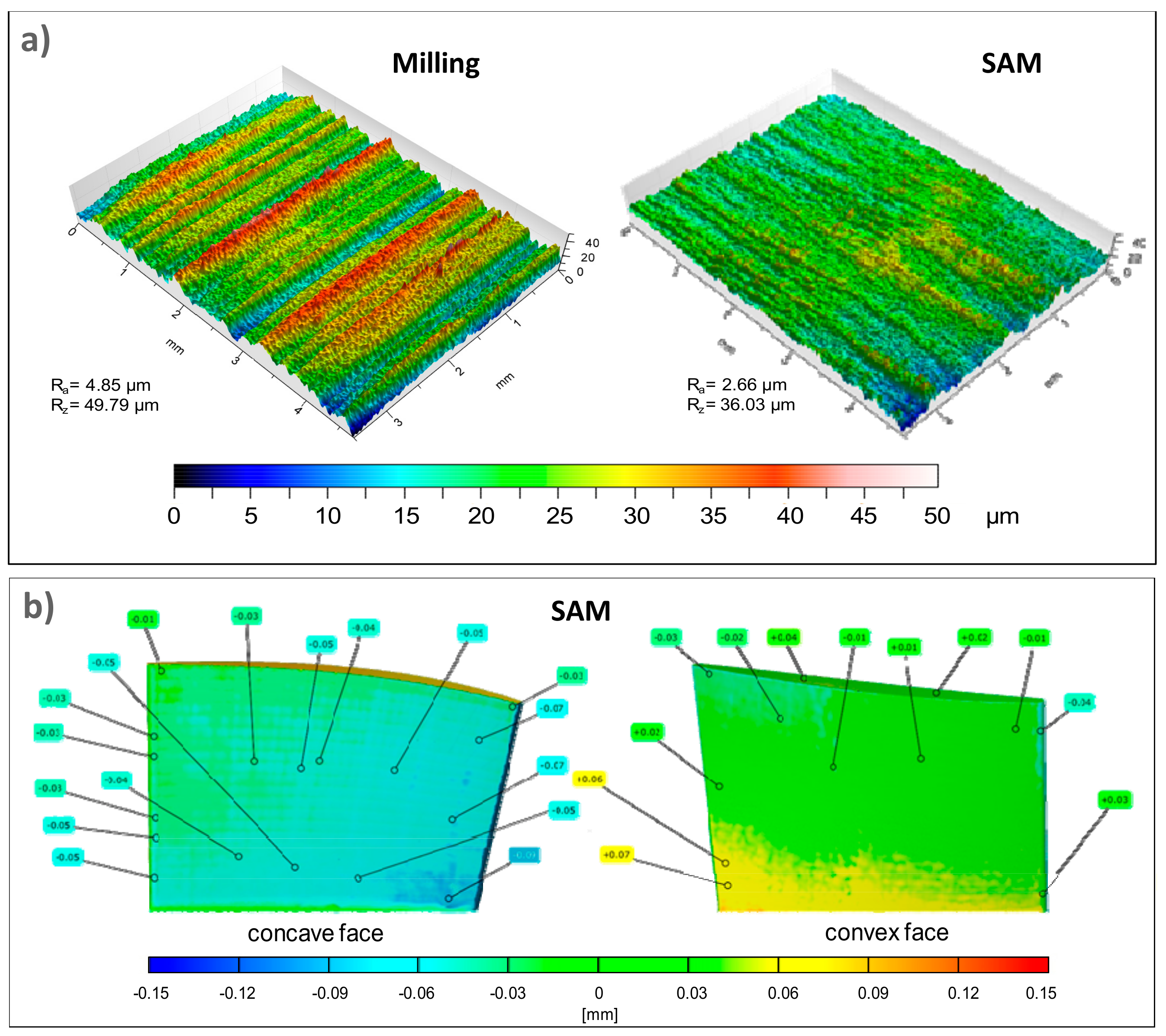
Figure 6 shows the cross-section perpendicular to the workpiece cutting direction for flank milling and flank SAM. Flank milling contained some irregularities on the machined surface with a macroscopic deviation. It is possible that this is as a result of aggressive cutting conditions with thermo-resistant superalloys. Furthermore, as an extra difficulty in the designed tests consisted on opening a full slot, this implied inadequate space for chip removal and refrigeration. Hence, the cutting tool is more prone to suffer from tooth breakage instead of regular wear [39].
On the contrary, the flank SAM top layer presented a regular finished surface with a minimal deviation. This is the consequence of utilizing grinding tools instead of milling tools; these tools have a wear type more regular even in the case of grain detachment [40]. These results explained extensively roughness obtained values. Regarding surface finishing, flank SAM offered a more stable behaviour comparing with conventional technique. This implies the possibility of reducing machining steps in real pieces with the aim of obtaining final surfaces.
The formation of white layer consists of a hard surface layer formed by ferrous materials whilst using high cutting temperatures that can modify the surface integrity. It is produced by a rapid heating during machining over austenitizing temperature and followed by a quick cooling of this surface [41]. Some experts related the existence of this white layer for nickel-based superalloys not only with the high heat during the process but with the low thermal conductivity property of these materials [42]. In order to detect this layer, it is shown in the microscope as a thin white layer. It is important to mention that the existence of the white layer implies a direct discard of technique or conditions if the size overpass is 2 µm [43]. The white layer depends on the cutting parameters and environment contributing to fatigue failure [29].
Chen-Wei Dai et al. [44] found white layer on the surface whilst grinding Inconel® 718 under extreme conditions due to the quick jump from rapid heating to cooling. In this line, considering roughing strategies for flank SAM and flank milling as hard cutting conditions and suffering considerable thermal changes, it is important to point out that no white layer was found for any of these techniques.
3.3. Residual Stress
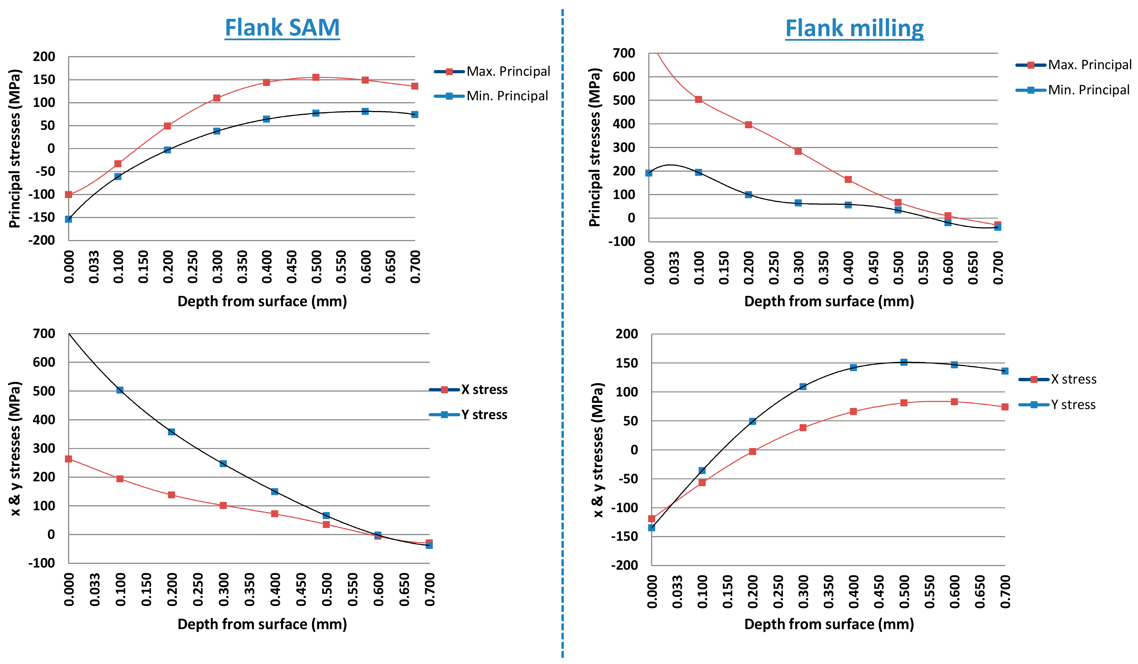
With the aim of measuring residual stress in the final fabricated surfaces and analysing differences between both techniques, hole-drilling strain gage method was selected [45]. According to the selected material, properties for determining residual stresses were established as: Young’s modulus (206 GPa), Poisson’s ratio (0.294), or yield stress (550MPa). The rosette type selected was 062 UL with a mean diameter of 5.13 mm, the hole diameter was 1.94 mm and a limit depth of 0.75 mm. The relation between hole diameter and maximum depth is 0.75/1.94 = 0.386. In line with ASTM standard E837 [45], when applying blind-hole drilling residual stress analysis the relation between hole diameter (D) and maximum hole depth (Z) is specified as Z/D = 0.4. Figure 7 shows the obtained results of principal stresses and each axis stress for flank SAM and flank milling, respectively.
According to residual stresses obtained results, for flank milling technique it was appreciated a tensile residual stress near to machined surface common for this technique [46]. On the contrary, flank SAM measurements showed a compressive pattern residual stress near to the manufactured surface. Additionally to the differences between obtained values magnitude, the most remarkable aspect is that flank SAM values are compressive values, usual for grinding techniques. This implies better behaviour to fatigue failure and prevents brittle fracture.
3.4. Microhardness
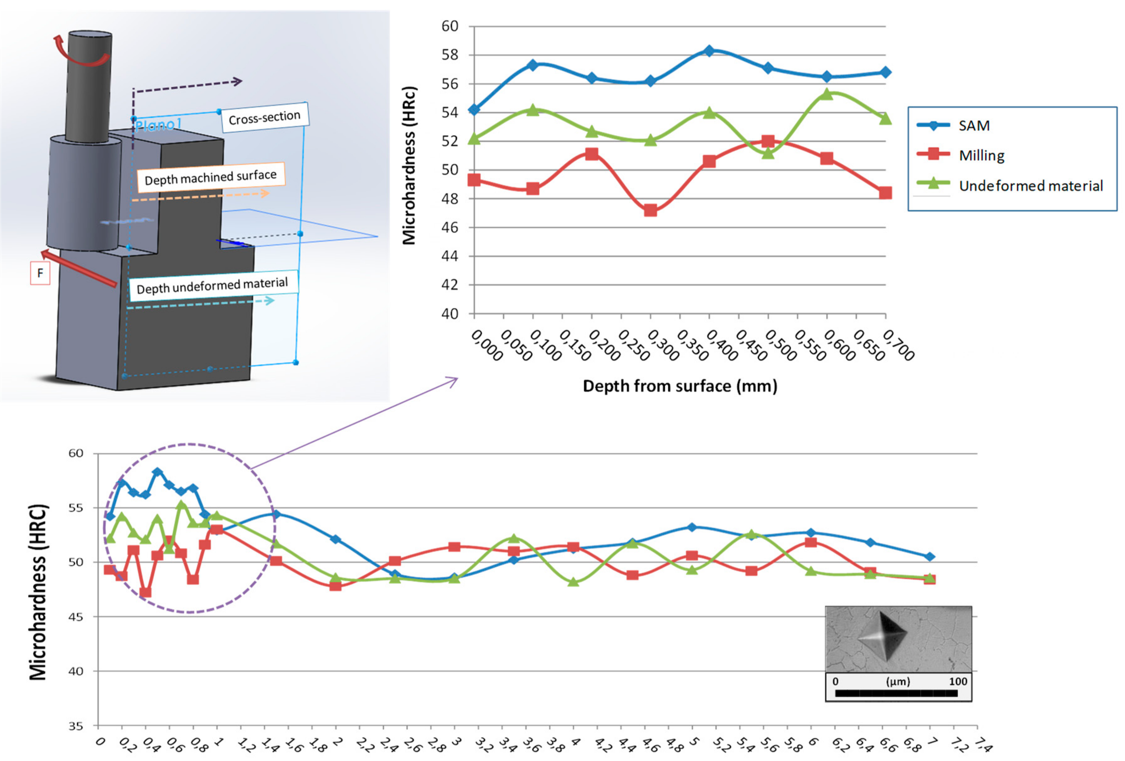
Related to material properties, microhardness was measured for material base, flank milling, and flank SAM. Following the ASTM standard E384 [47] that covers microindentation hardness testing, the Vickers test was selected. Figure 8 shows the Vickers indenter used and the obtained results. According to the ASTM standard E140 [48], these values were converted internally into Rockwell hardness, the more commonly used unit for these materials.
The measuring length along the first 1 mm was 0.1 mm and over this value was 0.5 mm. This was carried out in order to obtain more information close to machined surface. The results showed that undeformed material microhardness presents an average of 52 HRC, with a minimum of 49 HRC and maximum of 55 HRC. These values were set as a reference to study material property variation for both manufacturing techniques. Regarding the machined areas, differences were observed in the first 0.8 mm; approximately the same depth residual stresses were stabilized. In the case of flank milling, microhardness was situated within 46.5 HRC and 53 HRC. Conversely, for flank SAM an increase was observed in microhardness values up to 58 HRC. These values are a direct consequence of the appearance of compressive residual stresses on the machined surface; compressive stresses implied a rise in hardness values. This behavior is in concordance with the study carried out by Hua et al. [49] in which the increase of hardness was related with the maximum hardness value.
4. Conclusions
In this work, full slots were manufactured in Inconel® 718 with the main objective of comparing flank milling and flank SAM techniques in conventional machining centers. The new concept of using SAM as a roughing technique apart from finishing strategies leads to considerer this technique as a robust alternative for traditional milling. Additionally, the possibility of adapting a conventional machine to the use of both technologies fits with the trend of multitasking machines.
For this study, both techniques were compared from a technical point of view. In particular, surface roughness, microstructure, white layer, residual stresses, and microhardness were analyzed. The main conclusions obtained are listed below:
- Regarding surface roughness, flank SAM presented lower values for surface roughness comparing with flank milling. These results lead to consider flank SAM technique as an alternative for roughing strategies applied to these difficult-to-cut materials. Furthermore, obtained results conclude to the capability of using this technique for replacing intermediate manufacturing stages as semi-finishing strategies.
- Concerning cross-section, it was observed that conventional technique generated irregularities on the machined surface. This is directly related to the differences presented on roughness values. The reason why surface irregularities was avoided with flank SAM derived from the tool type. In this case, the use of grinding tools maintained a more constant tool wear and consequently a regular surface finishing. Additionally, it needs to be pointed that no white layer was found in any case.
- Related to residual stresses, considering the importance of the appearance of residual stress (both tensile and compressive), it should be highlighted that compressive residual stresses and tensile residual stresses arose on the machined surface by flank SAM and flank milling respectively, obtaining values five times higher for the conventional technique. Furthermore, compressive residual stresses in some processes add value to the machined material properties, such as better behavior to fatigue failure.
- Finally, microhardness showed higher values on the flank SAM surface. This improvement of the material property is a direct product of compressive residual stresses.
Therefore, from a technical point of view related with surface integrity in terms of surface roughness, residual stresses, microstructure and microhardness, the results obtained in this experiment showed that flank SAM technology does not present a limitation for being used with conventional machines; as long as cutting conditions were adequately adapted to spindle rotary capacity. This novel technology implies better results than conventional milling obtaining a suitable, controllable and predictable process to manufacture high added value components made of heat-resistant super alloys, such as Inconel® 718.
Author Contributions
H.G. and O.P. designed and performed the experiments. On the other hand, H.G. and O.P. wrote the paper. Additionally, A.C. analyzed the data related with residual stress and microstructure and A.F.-V. analyzed the data related to microhardness and white layer, and supervised the experiments. Finally, L.N.L.d.L. contributed with the resources (machine, tools, material, etc.) and supervised all the work carried out in this research.
Acknowledgments
The authors wish to acknowledge the financial support received from the Spanish Ministry of Economy and Competitiveness with the project TURBO (DPI2013-46164-C2-1-R), grant number [BES-2014-068874], to HAZITEK program from the Department of Economic Development and Infrastructures of the Basque Government and from FEDER funds, related to the HEMATEX project and Vice-chancellor of Innovation, Social Compromise and Cultural Action from UPV/EHU (the Bizialab program from the Basque Government). Finally, thanks are also addressed to Spanish Project MINECO DPI2016-74845-R and RTC-2014-1861-4.
Conflicts of Interest
The authors declare no conflict of interest. The founding sponsors had no role in the design of the study; in the collection, analyses, or interpretation of data; in the writing of the manuscript, or in the decision to publish the results.
References
- Campbell, F. Manufacturing Technology for Aerospace Structural Material, 1st ed.; Elsevier Science: Amsterdam, The Netherlands, 2006; pp. 221–272. ISBN 13: 9781856174954. [Google Scholar]
- Moussaoui, K.; Mouseigne, M.; Senatore, J.; Chieragatti, R.; Lamesle, P. Influence of milling on the fatigue lifetime of a Ti6Al4V titanium alloy. Metals 2015, 5, 1148–1162. [Google Scholar] [CrossRef]
- Klocke, F.; Zeis, M.; Klink, A.; Veselovac, D. Technological and economical comparison of roughing strategies via milling, sinking-EDM, wire-EDM and ECM for titanium- and nickel-based blisks. CIRP J. Manuf. Sci. Technol. 2013, 6, 198–203. [Google Scholar] [CrossRef]
- Thellaputta, G.R.; Bose, P.S.C.; Rao, C.S.P. Machinability of Nickel Based Superalloys: A Review. Mater. Today Proc. 2017, 4, 3712–3721. [Google Scholar] [CrossRef]
- Klocke, F.; Krämer, K.; Sangermann, H.; Lung, D. Thermo-mechanical tool load during high performance cutting of hard-to-cut materials. Procedia CIRP 2012, 1, 295–300. [Google Scholar] [CrossRef]
- Chen, Z.; Zhou, J.M.; Peng, R.L.; M´Saoubi, R.; Gustafsson, D.; Palmert, F.; Moverare, J. Plastic deformation and residual stress in high speed turning of AD730TM Nickel-based Superalloy with PCBN and WC tools. Procedia CIRP 2018, 71, 440–445. [Google Scholar] [CrossRef]
- Wu, C.Y. Arbitrary surface flank milling & flank SAM in the design and manufacturing of jet engine fan and compressor airfoils. In Proceedings of the ASME Turbo Expo 2012: Turbine Technical Conference and Exposition, Copenhagen, Denmark, 11–15 June 2012; ASME Digital Collection: Copenhagen, Denmark, 2012. [Google Scholar]
- Pereira, O.; Rodríguez, A.; Barreiro, J.; Rodríguez, A.; Fernández-Abia, A.I.; López de Lacalle, L.N. Nozzle design of combined use of MQL and cryogenic gas in machining. Int. J. Precis. Eng. Manuf.-Green Technol. 2017, 4, 87–95. [Google Scholar] [CrossRef]
- Pereira, O.; Martín-Alfonso, J.E.; Rodríguez, A.; Calleja, A.; Fernández-Valdivielso, A.; López de Lacalle, L.N. Sustainability analysis of lubricant oils for minimum quantity lubrication based on their tribo-rheological performance. J. Clean. Prod. 2017, 164, 1419–1429. [Google Scholar] [CrossRef]
- Li, L.; Guo, Y.B.; Wei, X.T.; Li, W. Surface integrity characteristics in wireEDM of Inconel 718 at different discharge energy. Procedia CIRP 2013, 6, 220–225. [Google Scholar] [CrossRef]
- Godino, L.; Pombo, I.; Sanchez, J.A.; Alvarez, J. On the development and evolution of wear flats in microcrystalline sintered alumina grinding wheels. J. Manuf. Process. 2018, 32, 494–505. [Google Scholar] [CrossRef]
- Jahanbakhsh, M.; Akhavan Farid, A.; Lotfi, M. Optimal flank wear in turning of Inconel 625 super-alloy using ceramic tool. Proc. Inst. Mech. Eng. Part B J. Eng. Manuf. 2016, 232, 208–216. [Google Scholar] [CrossRef]
- Ghoreishi, R.H.; Roohi, A.; Dehghan Ghadikolaei, A. Analysis of the influence of cutting parameters on surface roughness and cutting forces in high speed face milling of Al/SiC MMC. Mater. Res. Express 2018, 5, 086521. [Google Scholar] [CrossRef]
- Klocke, F.; Schmitt, R.; Zeis, M.; Heidemanns, L.; Kerkhoff, J.; Heinen, D.; Klink, A. Technological and economical assessment of alternative process chains for blisk manufacture. Procedia CIRP 2015, 35, 67–72. [Google Scholar] [CrossRef]
- Dehghan Ghadikolaei, A.; Vahdati, M. Experimental study on the effect of finishing parameters on surface roughness in magneto-rheological abrasive flow finishing process. Proc. Inst. Mech. Eng. Part B J. Eng. Manuf. 2014, 229, 1517–1524. [Google Scholar] [CrossRef]
- Chandra Verma, G.; Kala, P.; Mohan Pandey, P. Experimental investigations into internal magnetic abrasive finishing of pipes. Int. J. Adv. Manuf. Technol. 2017, 88, 1657–1668. [Google Scholar] [CrossRef]
- Sánchez, J.A.; López de Lacalle, L.N.; Lamikiz, A.; Bravo, U. Dimensional accuracy optimisation of multi-stage planetary EDM. Int. J. Mach. Tools Manuf. 2002, 42, 1643–1648. [Google Scholar] [CrossRef]
- Wang, J.; Guo, Y.B.; Fu, C.; Jia, Z. Surface integrity of alumina machines by electrochemical discharge assisted diamond wire sawing. J. Manuf. Process. 2018, 31, 96–102. [Google Scholar] [CrossRef]
- Flaño, O.; Ayesta, I.; Izquierso, B.; Sánchez, J.A.; Zhao, Y.; Kunieda, M. Improvement of EDM performance in high-aspect ratio slot machining using multi-holed electrodes. Precis. Eng. 2018, 51, 223–231. [Google Scholar] [CrossRef]
- Włodzimierz, W.; Jacek, T. Modern technology of the turbine blades removal machining. In Proceedings of the 8 International Conference Advanced Manufacturing Operations, Kranevo, Bulgaria, 18–20 June 2008. [Google Scholar]
- Erickson, R.E.; Faughnan, P.R., Jr. Method of Machining Integral Bladed Rotors for a Gas Turbine Engine. U.S. Patent 7967659 B2, 28 June 2011. [Google Scholar]
- Schwartz, B.J.; Vaillette, B.D.; Wu, C.Y.; Colacino, G.J.; Packman, A.B.; United Technologies Corp. Flank Superabrasive Machining. U.S. Patent 7,101,263, 5 September 2006. [Google Scholar]
- Marinescu, I.; Hitchiner, M.; Uhlmann, E. Handbook of Machining with Grinding Wheels; Taylor & Francis Group: Boca Raton, FL, USA, 2006; ISBN 9781574446715. [Google Scholar]
- Petrilli, R. Super abrasive machining for PM. Met. Powder Rep. 2012, 67, 38–41. [Google Scholar] [CrossRef]
- Guo, C.; Ranganath, S.; McIntosh, D.; Elfizy, A. Virtual high performance grinding with CBN wheels. CIRP Ann. Manuf. Technol. 2008, 57, 325–328. [Google Scholar] [CrossRef]
- Aspinwall, D.K.; Soo, S.L.; Curtis, D.T.; Mantle, A.L. Profiled superabrasive grinding wheels for the machining of a nickel based superalloy. CIRP Ann. Manuf. Technol. 2007, 56, 335–338. [Google Scholar] [CrossRef]
- González, H.; Calleja, A.; Pereira, O.; Ortega, N.; López de Lacalle, L.N.; Barton, M. Super Abrasive Machining of Integral Rotary Components Using Grinding Flank Tools. Metals 2018, 8, 24. [Google Scholar] [CrossRef]
- Sharman, A.R.C.; Hughes, J.I.; Ridgway, K. An analysis of the residual stresses generated in Inconel 718TM when turning. J. Mater. Process. Technol. 2006, 173, 359–367. [Google Scholar] [CrossRef]
- Thakur, A.; Gangopadhyay, S. State-of-the-art in surface integrity in machining of nickel-based super alloys. Int. J. Mach. Tools Manuf. 2016, 100, 25–54. [Google Scholar] [CrossRef]
- Pottlacher, G.; Hosaeus, H.; Kaschnitz, E.; Seifter, A. Thermophysical properties of solid and liquid Inconel 718 Alloy. Scand. J. Metall. 2002, 31, 161–168. [Google Scholar] [CrossRef]
- Artetxe, E.; González, H.; Calleja, A.; Fernández Valdivielso, A.; Polvorosa, R.; Lamikiz, A.; López de Lacalle, L.N. Optimised methodology for aircraft engine IBRs five-axis machining process. Int. J. Mechatron. Manuf. Syst. 2016, 9, 385–401. [Google Scholar] [CrossRef]
- Thakur, D.G.; Ramamoorthy, B.; Vijayaraghavan, L. Study on the machinability characteristics of superalloy Inconel 718 during high speed turning. Mater. Des. 2009, 30, 1718–1725. [Google Scholar] [CrossRef]
- Costes, J.P.; Guillet, Y.; Poulachon, G.; Dessoly, M. Tool-life and wear mechanisms of CBN tools in machining of Inconel 718. Int. J. Mach. Tools Manuf. 2007, 47, 1081–1087. [Google Scholar] [CrossRef] [Green Version]
- Kitagawa, T.; Kubo, A.; Maekawa, K. Temperature and wear of cutting in high-speed machining of Inconel 718 and Ti-6Al-6V-2Sn. Wear 1997, 202, 142–148. [Google Scholar] [CrossRef]
- Fernández de Larrinoa, J. Optimización de procesos de recubrimiento para herramientas de corte. In Tecnologías de Recubrimiento, Métodos de Caracterización y Optimización de las Propiedades; University of the Basque Country: Bilbao, Spain, 2015. [Google Scholar]
- Vidal, G.; Ortega, N.; Bravo, H.; Dubar, M.; González, H. An Analysis of Electroplated cBN Grinding Wheel Wear and Conditioning during Creep Feed Grinding of Aeronautical Alloys. Metals 2018, 8, 350. [Google Scholar] [CrossRef]
- Marinescu, I.D.; Rowe, W.B.; Dimitrov, B.; Inasaki, I. Tribology of Abrasive Machining Processe; William Andrew: Norwich, NY, USA, 2004; pp. 341–412. ISBN 0-8155-1490-5. [Google Scholar]
- Geometrical Product Specifications (GPS), Surface Texture: Profile Method, Rules and Procedures for the Assessment of Surface Texture; ISO Standard 4288; ISO: Geneva, Switzerland, 1996.
- López de Lacalle Luis, N.; Lamikiz, A.; Sánchez, J.A.; Arana, J.L. Improving the surface finish in high speed milling of stamping dies. J. Mater. Process. Technol. 2002, 123, 292–302. [Google Scholar] [CrossRef]
- Wenfeng, D.; Linke, B.; Yejun, Z.; Zheng, L.; Yucan, F.; Honghua, S.; Jiuhua, X. Review on monolayer CBN superabrasive wheels for grinding metallic materials. Chin. J. Aeronaut. 2017, 30, 109–134. [Google Scholar]
- Hosseini, S.; Beno, T.; Klement, U.; Kaminski, J.; Ryttberg, K. Cutting temperatures during hard turning Measurements and effects on white layer formation in AISI 52100. J. Mater. Process. Technol. 2014, 214, 1293–1300. [Google Scholar] [CrossRef]
- Herbert, C.R.J.; Kwong, J.; Kong, M.C.; Axinte, D.A.; Hardy, M.C.; Withers, P.J. An evaluation of the evolution of workpiece surface integrity in hole making operations for a nickel-based super alloy. J. Mater. Process. Technol. 2012, 212, 1723–1730. [Google Scholar] [CrossRef]
- Smith, S.; Melkote, S.N.; Lara-Curzio, E.; Watkins, T.R.; Allard, L.; Riester, L. Effect of surface integrity of hard turned AISI 52100 steel on fatigue performance. Mater. Sci. Eng. 2007, 459, 337–346. [Google Scholar] [CrossRef]
- Dai, C.W.; Ding, W.F.; Zhu, Y.J.; Xu, J.H.; Yu, H.W. Grinding temperature and power consumption in high speed grinding of Inconel 718 nickel-based superalloy with a vitrified CBN wheel. Precis. Eng. 2018, 52, 192–200. [Google Scholar] [CrossRef]
- Determining Residual Stresses by the Hole-Drilling Strain-Gage Method; ASTM Standard E 837; ASTM International: West Conshohocken, PA, USA, 2013.
- Denkena, B.; De Leon, L. Milling Induced Residual Stresses in Structural Parts out of Forged Aluminum Alloys. Int. J. Mach. Machinab. Mater. (IJMMM) 2008, 4, 335–344. [Google Scholar]
- Standard Test Method for Microindentation Hardness of Materials; ASTM Standard E 384; ASTM International: West Conshohocken, PA, USA, 2017.
- Standard Hardness Conversion Tables for Metals Relationship Among Brinell Hardness, Vickers Hardness, Rockwell Hardness, Superficial Hardness, Knoop Hardness, and Scleroscope Hardness; ASTM Standard E140; ASTM International: West Conshohocken, PA, USA, 2012.
- Hua, J.; Shivpuri, R.; Cheng, X.; Bedekar, V.; Matsumoto, Y.; Hashimoto, F.; Watkins, T.R. Effect of feed rate, workpiece hardness and cutting edge on subsurface residual stress in the hard turning of bearing steel using chamfer+hone cutting edge geometry. Mater. Sci. Eng. A 2005, 394, 238–248. [Google Scholar] [CrossRef]
Figure 1.
SAM vs. conventional milling obtained results: roughness (a) and dimensional deviation (b) [27].
Figure 1.
SAM vs. conventional milling obtained results: roughness (a) and dimensional deviation (b) [27].

Figure 2.
Microstructure of Inconel® 718.
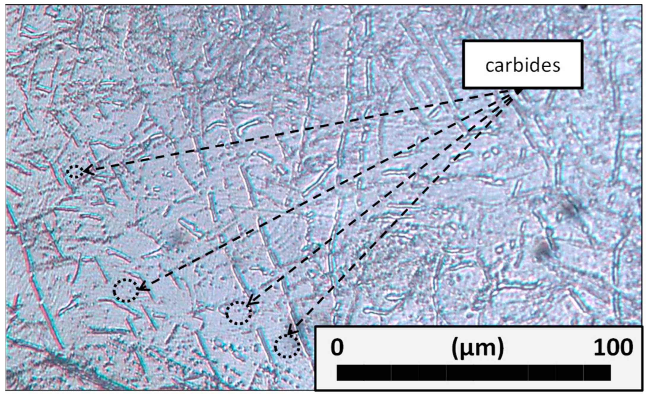
Figure 3.
Experimental setup at the University of the Basque Country (UPV/EHU).

Figure 4.
Grinding process parameters definition.

Figure 5.
Roughness values (Ra and Rz) for flank milling and flank SAM.

Figure 6.
Cross-section of the Inconel® 718 surface after flank milling and flank SAM.

Figure 7.
Residual stresses obtained for flank SAM and flank milling on Inconel® 718.

Figure 8.
Residual stresses obtained for flank SAM and flank milling on Inconel® 718.


Table 1.
Inconel® 718 chemical composition, mechanical and physical properties [34].
Table 1.
Inconel® 718 chemical composition, mechanical and physical properties [34].
| Chemical Composition (%) | ||||||||||||
| Ni | Cr | Co | Fe | Nb | Mo | Ti | Al | B | C | Mn | Si | Others |
| 52.5 | 19 | 1 | 17 | 5 | 3 | 1 | 0.6 | 0.01 | 0.08 | 0.35 | 0.35 | 1.79 |
| Mechanical and Physical Properties | ||||||||||||
| Hardness | Young’s Modulus | Tensile Strength | Density | Specific Heat | Melting Temp. | Thermal Conduct | ||||||
| 42 HRc | 206 GPa | 1.73 GPa | 8470 kg/m3 | 461 J/(kg·K) | 1550 K | 15 W/(m·K) | ||||||
Table 2.
Defined cutting conditions for the experiments.
| Cutting Conditions | Flank Milling | Flank SAM |
|---|---|---|
| Feed Rate | 0.01 mm/tooth | 45 mm/min |
| Cutting Speed | 20 m/min | 900 m/min |
| ap | 20 mm | 20 mm |
| ae | 16 mm | 16 mm |
| Cutting Fluid | Synthetic oil emulsion Houghton® 20% | Synthetic oil emulsion Houghton® 20% |
© 2018 by the authors. Licensee MDPI, Basel, Switzerland. This article is an open access article distributed under the terms and conditions of the Creative Commons Attribution (CC BY) license (http://creativecommons.org/licenses/by/4.0/).
Share and Cite
MDPI and ACS Style
González, H.; Pereira, O.; Fernández-Valdivielso, A.; López de Lacalle, L.N.; Calleja, A. Comparison of Flank Super Abrasive Machining vs. Flank Milling on Inconel® 718 Surfaces. Materials 2018, 11, 1638. https://doi.org/10.3390/ma11091638
AMA Style
González H, Pereira O, Fernández-Valdivielso A, López de Lacalle LN, Calleja A. Comparison of Flank Super Abrasive Machining vs. Flank Milling on Inconel® 718 Surfaces. Materials. 2018; 11(9):1638. https://doi.org/10.3390/ma11091638
Chicago/Turabian StyleGonzález, Haizea, Octavio Pereira, Asier Fernández-Valdivielso, L. Norberto López de Lacalle, and Amaia Calleja. 2018. "Comparison of Flank Super Abrasive Machining vs. Flank Milling on Inconel® 718 Surfaces" Materials 11, no. 9: 1638. https://doi.org/10.3390/ma11091638
Note that from the first issue of 2016, this journal uses article numbers instead of page numbers. See further details here.