Independently Tunable Fano Resonances Based on the Coupled Hetero-Cavities in a Plasmonic MIM System


Abstract
:1. Introduction
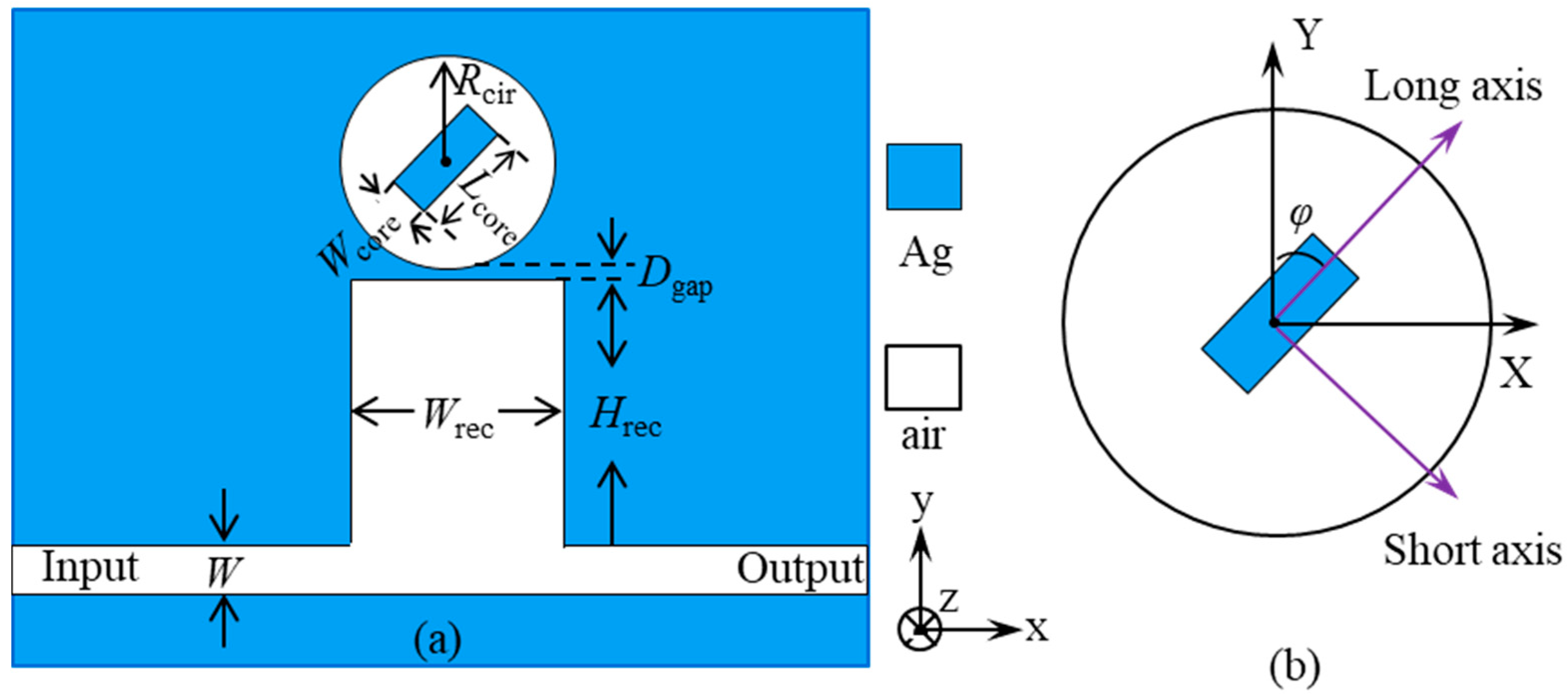
2. Structure Design
3. Results and Discussion
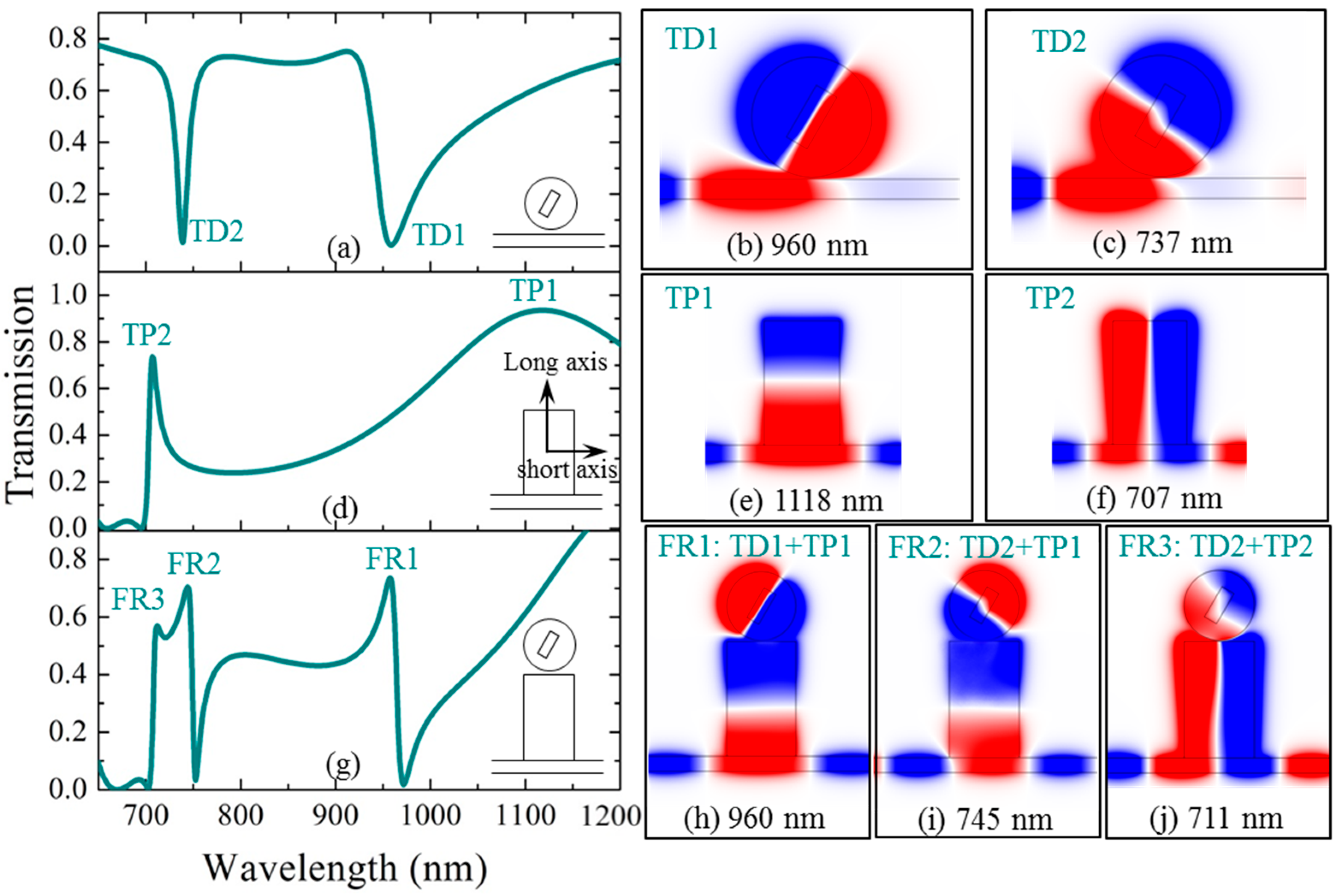
3.1. The Coupling Mechanism of the Three Fano Resonances
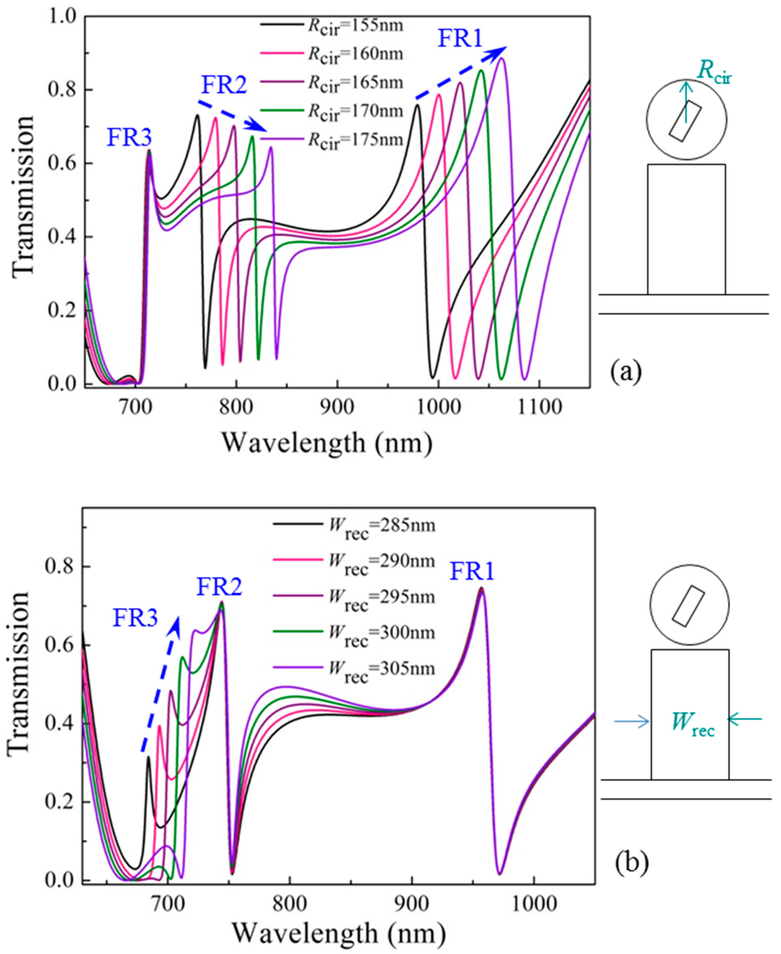
3.2. The Characteristics of Independent Tunability of the Three Fano Resonances
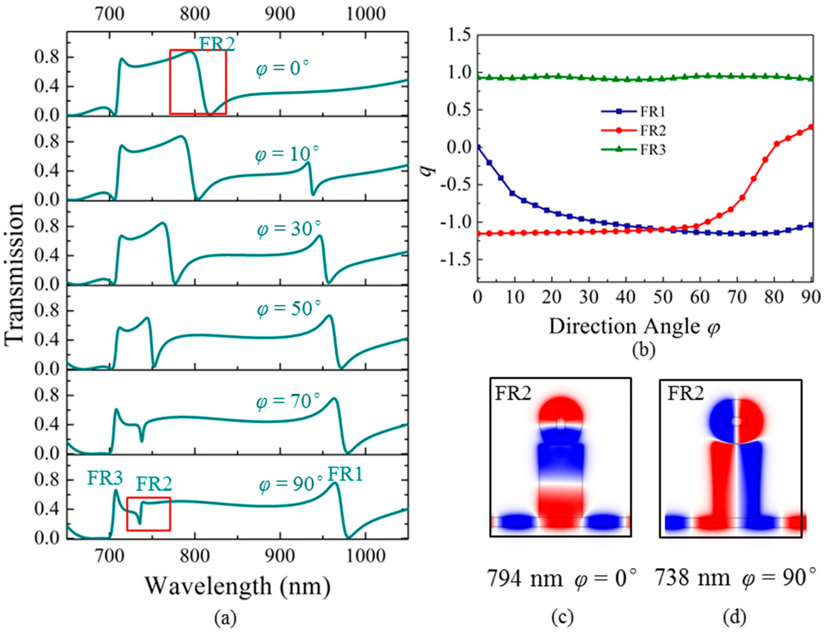
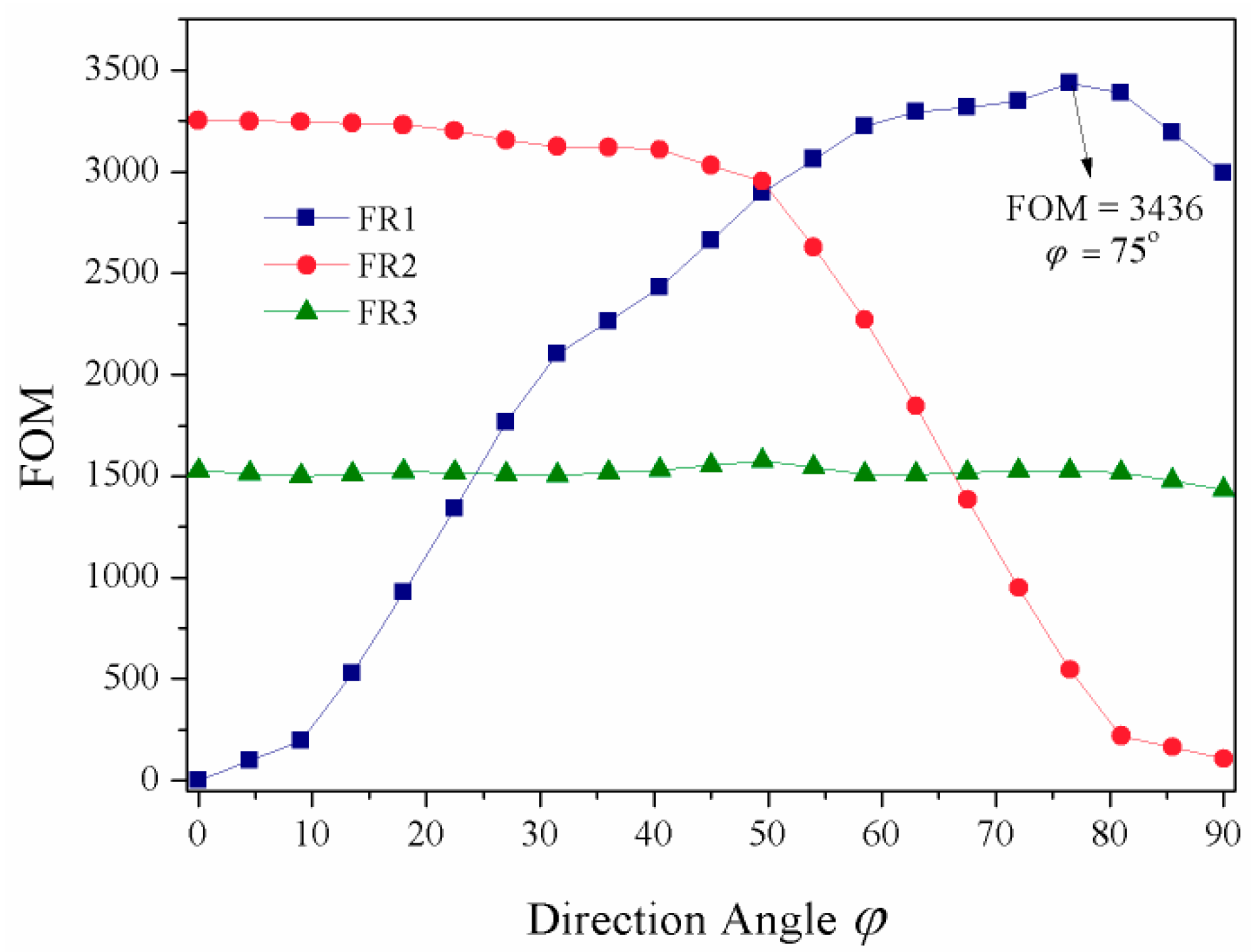
3.3. Tuning Fano Resonances by Changing the Direction Angle of the Metal Strip
4. Conclusions
Author Contributions
Funding
Conflicts of Interest
References
- Caldwell, J.D.; Lindsay, L.; Giannini, V.; Vurgaftman, I.; Reinecke, T.L.; Maier, S.A.; Glembocki, O.J. Low-loss, infrared and terahertz nanophotonics using surface phonon polaritons. Nanophotonics 2015, 4, 44–68. [Google Scholar] [CrossRef] [Green Version]
- Lin, J.; Balthasar Mueller, J.P.; Wang, Q.; Yuan, G.H.; Antoniou, N.; Yuan, X.C.; Capasso, F. Polarization-controlled tunable directional coupling of surface plasmon polaritons. Science 2013, 340, 331–334. [Google Scholar] [CrossRef] [PubMed]
- Williams, C.R.; Andrews, S.R.; Maier, S.A.; Fernandez-Dominguez, A.I.; Martin-Moreno, L.; Garcia-Vidal, F.J. Highly confined guiding of terahertz surface plasmon polaritons on structured metal surfaces. Nat. Photonics 2008, 2, 175–179. [Google Scholar] [CrossRef]
- Brawley, Z.T.; Bauman, S.J.; Darweesh, A.A.; Debu, D.T.; Ladani, F.T.; Herzog, J.B. Plasmonic Au array SERS substrate with optimized thin film oxide substrate layer. Materials 2018, 11, 942. [Google Scholar] [CrossRef] [PubMed]
- Rifat, A.A.; Rahmani, M.; Xu, L.; Miroshnichenko, A.E. Hybrid metasurface based tunable near-perfect absorber and plasmonic sensor. Materials 2018, 11, 1091. [Google Scholar] [CrossRef] [PubMed]
- Zayats, A.V.; Smolyaninov, I.I.; Maradudin, A.A. Nano-optics of surface plasmon polaritons. Phys. Rep. 2005, 408, 131–314. [Google Scholar] [CrossRef]
- Zhou, S.Y.; Lin, J.Y.; Wong, S.W.; Deng, F.; Zhu, L.; Yang, Y.; He, Y.J.; Tu, Z.H. Spoof surface plasmon polaritons power divider with large Isolation. Sci. Rep. 2018, 8, 5947. [Google Scholar] [CrossRef] [PubMed]
- Giannini, V.; Francescato, Y.; Amrania, H.; Phillips, C.C.; Maier, S.A. Fano resonances in nanoscale plasmonic systems: A parameter-free modeling approach. Nano Lett. 2011, 11, 2835–2840. [Google Scholar] [CrossRef] [PubMed]
- Lassiter, J.B.; Sobhani, H.; Knight, M.W.; Mielczarek, W.S.; Nordlander, P.; Halas, N.J. Designing and deconstructing the Fano lineshape in plasmonic nanoclusters. Nano Lett. 2012, 12, 1058–1062. [Google Scholar] [CrossRef] [PubMed]
- Lukyanchuk, B.; Zheludev, N.I.; Maier, S.A.; Halas, N.J.; Nordlander, P.; Giessen, H.; Chong, C.T. The Fano resonance in plasmonic nanostructures and metamaterials. Nat. Mater. 2010, 9, 707–715. [Google Scholar] [CrossRef] [PubMed]
- Limonov, M.F.; Rybin, M.V.; Poddubny, A.N.; Kivshar, Y.S. Fano resonances in photonics. Nat. Photonics 2017, 11, 543–554. [Google Scholar] [CrossRef]
- Zafar, R.; Salim, M. Analysis of asymmetry of Fano resonance in plasmonic metal-insulator-metal waveguide. Photonics Nanostruct. Fundam. Appl. 2017, 23, 1–6. [Google Scholar] [CrossRef]
- Li, S.L.; Wang, Y.L.; Jiao, R.Z.; Wang, L.L.; Duan, G.Y.; Yu, L. Fano resonances based on multimode and degenerate mode interference in plasmonic resonator system. Opt. Express 2017, 25, 3525–3533. [Google Scholar] [CrossRef] [PubMed]
- Chen, J.J.; Sun, C.W.; Gong, Q.H. Fano resonances in a single defect nanocavity coupled with a plasmonic waveguide. Opt. Lett. 2014, 39, 52–55. [Google Scholar] [CrossRef] [PubMed]
- Miroshnichenko, A.E.; Kivshar, Y.S.; Vicencio, R.A.; Molina, M.I. Fano resonance in quadratic waveguide arrays. Opt. Lett. 2005, 30, 872–874. [Google Scholar] [CrossRef] [PubMed]
- Kobayashi, K.; Aikawa, H.; Sano, A.; Katsumoto, S.; Iye, Y. Fano resonance in a quantum wire with a side-coupled quantum dot. Phys. Rev. B 2004, 70, 035319. [Google Scholar] [CrossRef] [Green Version]
- Miroshnichenko, A.E.; Flach, S.; Kivshar, Y.S. Fano resonances in nanoscale structures. Rev. Mod. Phys. 2010, 82, 2257. [Google Scholar] [CrossRef]
- Qi, J.W.; Chen, Z.Q.; Chen, J.; Li, Y.D.; Qiang, W.; Xu, J.J.; Sun, Q. Independently tunable double Fano resonances in asymmetric MIM waveguide structure. Opt. Express 2014, 22, 14688–14695. [Google Scholar] [CrossRef] [PubMed]
- Deng, Y.; Cao, G.T.; Yang, H.; Li, G.H.; Chen, X.S.; Lu, W. Tunable and high-sensitivity sensing based on Fano resonance with coupled plasmonic cavities. Sci. Rep. 2017, 7, 10639. [Google Scholar] [CrossRef] [PubMed]
- Zhan, S.P.; Peng, Y.Y.; He, Z.H.; Li, B.X.; Chen, Z.Q.; Xu, H.; Li, H.J. Tunable nanoplasmonic sensor based on the asymmetric degree of Fano resonance in MDM waveguide. Sci. Rep. 2016, 6, 22428. [Google Scholar] [CrossRef] [PubMed] [Green Version]
- Ren, X.B.; Ren, K.; Cai, Y.X. Tunable compact nanosensor based on Fano resonance in a plasmonic waveguide system. Appl. Opt. 2017, 56, H1–H9. [Google Scholar] [CrossRef] [PubMed]
- Sun, B.; Zhao, L.X.; Wang, C.; Yi, X.Y.; Liu, Z.Q.; Wang, G.H.; Li, J.M. Tunable Fano resonance in E-shape plasmonic nanocavities. J. Phys. Chem. C 2014, 118, 25124–25131. [Google Scholar] [CrossRef]
- Fu, Q.H.; Zhang, F.L.; Fan, Y.C.; He, X.; Qiao, T.; Kong, B.T. Electrically tunable Fano-type resonance of an asymmetric metal wire pair. Opt. Express 2016, 24, 11708–11715. [Google Scholar] [CrossRef] [PubMed]
- Chen, Z.; Song, X.K.; Duan, G.Y.; Wang, L.L.; Yu, L. Multiple Fano resonances control in MIM side-coupled cavities systems. IEEE Photonics J. 2015, 7, 2701009. [Google Scholar] [CrossRef]
- Zhang, B.H.; Wang, L.L.; Li, H.J.; Zhai, X.; Xia, S.X. Two kinds of double Fano resonances induced by an asymmetric MIM waveguide structure. J. Opt. 2016, 18, 065001. [Google Scholar] [CrossRef]
- Taheri, A.N.; Kaatuzian, H. Numerical investigation of a nano-scale electro-plasmonic switch based on metal-insulator-metal stub filter. Opt. Quantum Electron. 2015, 47, 159–168. [Google Scholar] [CrossRef]
- Rezaei, M.; Jalaly, S.; Miri, M.; Khavasi, A.; Fard, A.P.; Mehrany, K.; Rashidian, B. A distributed circuit model for side-coupled nanoplasmonic structures with metal-insulator-metal arrangement. IEEE J. Sel. Top. Quantum Electron. 2012, 18, 1692–1699. [Google Scholar] [CrossRef]
- Taheri, A.N.; Kaatuzian, H. Design and simulation of a nanoscale electroplasmonic 1 × 2 switch based on asymmetric metal-insulator-metal stub filters. Appl. Opt. 2014, 53, 6546–6553. [Google Scholar] [CrossRef] [PubMed]
- Ogawa, S.; Kimata, M. Metal-insulator-metal-based plasmonic metamaterial absorbers at visible and infrared wavelengths: A review. Materials 2018, 11, 458. [Google Scholar] [CrossRef] [PubMed]
- Chen, Z.; Hu, R.; Cui, L.N.; Yu, L.; Wang, L.L.; Xiao, J.H. Plasmonic wavelength demultiplexers based on tunable Fano resonance in coupled-resonator systems. Opt. Commun. 2014, 320, 6–11. [Google Scholar] [CrossRef]
- Jankovic, N.; Cselyuszka, N. Multiple Fano-like MIM plasmonic structure based on triangular resonator for refractive index sensing. Sensors 2018, 18, 287. [Google Scholar] [CrossRef] [PubMed]
- Genet, C.; Van Exter, M.P.; Woerdman, J.P. Fano-type interpretation of red shifts and red tails in hole array transmission spectra. Opt. Commun. 2003, 225, 331–336. [Google Scholar] [CrossRef] [Green Version]
- Wen, K.H.; Hu, Y.H.; Chen, L.; Zhou, J.Y.; Lei, L.; Guo, Z. Fano resonance with ultra-high figure of merits based on plasmonic metal-insulator-metal waveguide. Plasmonics 2015, 10, 27–32. [Google Scholar] [CrossRef]


© 2018 by the authors. Licensee MDPI, Basel, Switzerland. This article is an open access article distributed under the terms and conditions of the Creative Commons Attribution (CC BY) license (http://creativecommons.org/licenses/by/4.0/).
Share and Cite
Wang, Q.; Ouyang, Z.; Lin, M.; Liu, Q. Independently Tunable Fano Resonances Based on the Coupled Hetero-Cavities in a Plasmonic MIM System. Materials 2018, 11, 1675. https://doi.org/10.3390/ma11091675
Wang Q, Ouyang Z, Lin M, Liu Q. Independently Tunable Fano Resonances Based on the Coupled Hetero-Cavities in a Plasmonic MIM System. Materials. 2018; 11(9):1675. https://doi.org/10.3390/ma11091675
Chicago/Turabian StyleWang, Qiong, Zhengbiao Ouyang, Mi Lin, and Qiang Liu. 2018. "Independently Tunable Fano Resonances Based on the Coupled Hetero-Cavities in a Plasmonic MIM System" Materials 11, no. 9: 1675. https://doi.org/10.3390/ma11091675