Effects of Heat-Treatment Temperature on the Microstructure and Mechanical Properties of Steel by MgO Nanoparticle Additions


1
School of Metallurgical and Ecological Engineering, University of Science and Technology Beijing, Beijing 100083, China
2
School of Materials Science and Engineering, Shanghai Jiao Tong University, Shanghai 200240, China
*
Authors to whom correspondence should be addressed.
Materials 2018, 11(9), 1707; https://doi.org/10.3390/ma11091707
Submission received: 9 August 2018
/
Revised: 4 September 2018
/
Accepted: 9 September 2018
/
Published: 13 September 2018
Abstract
:The characteristics and formation mechanisms of intragranular acicular ferrite (IAF) in steel with MgO nanoparticle additions were systematically investigated for different isothermal heat-treatment temperatures, and its influence on mechanical properties was also clarified. The results indicate that the inclusions were finely dispersed and refined after adding MgO nanoparticles. In addition, with decreasing heat-treatment temperature, the microstructure changed from grain boundary ferrite (GBF) and polygonal ferrite (PF) to intragranular acicular ferrite. Moreover, the steel with MgO additions had excellent mechanical properties in the temperature range of 973 to 823 K and an average Charpy absorbed energies value of around 174 J at 873 K due to the significant refinement of the microstructure and nucleation of intragranular acicular ferrite.
1. Introduction
With the development of a new generation of steel materials, the cleanliness of steel has been significantly improved [1,2,3]. However, the complete removal of nonmetallic inclusions from liquid steel during the steelmaking process is almost impossible [4,5]. Therefore, Takamura et al. [6] and Mizoguchi et al. [7] proposed a new concept of oxide metallurgy, which uses small-sized inclusions and precipitates particles as nucleation sites of intragranular acicular ferrite (IAF) or pins austenite grains to improve the final properties of steel. Further research and applications of this technique have shown that nonmetallic inclusions induce the formation of IAF, which becomes the core point [8].
Up to now, these inclusions have been formed either by an internal precipitation method or by an external addition method [9]. Numerous studies have focused on the internal precipitation method, which mainly forms oxide inclusions through strong deoxidizer and alloying elements such as Mg [10,11], Ti [12,13], V [14], and Ce [15], and these inclusions become nucleation sites of IAF during the austenite (γ) → ferrite (α) transformation [16]. In addition, some researchers have suggested that inclusions such as ZrO2 [17], TiN [18], and MnS [19] can also act as heterogeneous nuclei for IAF. However, this method requires precise control of the refining process within a narrow operating window. Moreover, due to the complexity of the metallurgical chemical reaction and the instability of the steelmaking process, it is difficult to obtain the desired inclusion characteristics, especially the inclusion type and size. Therefore, in the past few decades, some researchers have proposed an external addition method, which mostly uses artificially added oxide powder such as Ti2O3 and ZrO2 to produce the desired inclusions types [20]. Kiviö et al. [21] reported that they had added to steel different additives with metallic Ti and TiO2. Samples brought for subsequent hot rolling and heat-treatment experiments to find out the grain-refining effect eventually formed IAF. Mu et al. [22] and Xuan et al. [23] investigated different powders such as Ti2O3 and TiN, which were used for steel samples to act as nucleation sites of IAF formation. Furthermore, recent studies have attempted to use various methods of externally adding different particles to obtain small-sized and uniformly distributed inclusions [24,25].
In the previous research of the author and his coworkers [26,27,28], a novel method for predispersing MgO nanoparticles with AlSi or AlTi alloy nanoparticles was applied. Small-sized inclusions could be obtained by adding nanoparticles to molten steel. For laboratory experiments, these nanoparticles could be added to liquid steel with a molybdenum rod in a tubular resistance furnace [26]. For industrial production, the nanoparticles could be added to liquid steel within the mold in the vicinity of the submerged nozzle outlet [27]. Meanwhile, several studies have reported the formation mechanism of IAF induced by the addition of nanoparticles. Gao et al. [28] determined that the Mn-depleted zone (MDZ) can be found around Ti2O3 and MgO–Al2O3 inclusions in steels by MgO addition, which can promote ferrite nucleation by increasing the chemical driving force. However, Mu et al. [29] reported that the MDZ was not formed around inclusions in steels by Ti2O3 addition. Similar conclusions were also drawn by Kang et al. [30]. Hence, it is of great significance to systematically investigate the formation mechanism of IAF in steel.
Although the addition of nanoparticles is very popular for the induction of IAF nucleation to improve the mechanical properties of steels, few researchers have systematically studied the nucleation of IAF and how to refine the microstructure, in particular, the effect of phase transformation temperatures on nucleation and growth of IAF during γ → α transformation. Therefore, the current study, based on previous studies, investigated the effects of isothermal treatment temperature on microstructure and mechanical properties. Then, the critical size of the inclusions for IAF nucleation was analyzed using theoretical calculations, and the mass fraction of the inclusions during solidification was predicted using FactSage software. Finally, the mechanism of IAF formation and the refinement of IAF to microstructure are discussed.
2. Experimental
2.1. Experimental Procedure
The low-carbon steel used in the present study was melted in a 6-kg vacuum induction furnace (Shenyang Vacuum Technology Institute Co., Ltd., Shenyang, China), and the mixed MgO nanoparticles were poured into the liquid steel through a charging hopper located under the furnace cover. In order to ensure that the MgO nanoparticles added to the steel melt were fully dispersed, another type of nanoparticle material, AlTi alloy, was used as a predispersion medium. The predispersion process of MgO nanoparticles was performed using a planetary ball mill (IKN Mechanical Equipment Co., Ltd., Berlin, Germany) with a weight ratio of MgO and AlTi alloy of 4:1. The rotation speed was maintained at 6000 rpm during the 3-h process which was conducted under low-oxygen and low-temperature conditions. The microstructure and crystal structure of MgO and AlTi alloy nanoparticles are shown in Figure 1. The detailed operational parameters and processes of the nanoparticles have been reported by previous studies by the author and his coworkers [26]. Then, the melt was cast into ingots and was cooled to room temperature in the air. Subsequently, the ingots were heated at 1473 K for 1 h to homogenize the elements, hot forged into a rectangular shape with the size of 40 × 120 × 120 mm3 at a temperature ranging from 1323 to 1073 K, and then air cooled to room temperature. The chemical composition of the steel was determined using optical emission spectroscopy and is given in Table 1.
To evaluate the effect of the different phase transformation temperatures on IAF, first, thermodynamic software was used to predict the phase transformation temperatures under equilibrium conditions to provide theoretical guidance for the experiment. The phase transformation temperatures, Ae1 and Ae3, were calculated by FactSage7.1 software (Centre for Research in Computational Thermochemistry, Montreal, QC, Canada,) (Figure 2a) to be 723 and 1058 K, respectively. The TTT (Time, Temperature, Transformation) diagram was established by JMatPro software (Version 10.0, Sente Software Ltd., London, UK) as shown in Figure 2b, and the tip temperature was 919 K during γ → α transformation. The isothermal heat-treatment processes were as follows: Specimens with a size of 12 × 120 × 50 mm3 from forged steels were heated to 1323 K at a rate of 10 K/min and held at this temperature for 20 min before being cooled to the corresponding salt bath temperature at the same rate. Subsequently, the isothermal treatment temperatures based on the TTT diagram were carried out at 973, 923, 873, and 823 K for 30 min, respectively. For convenience, the specimens were orderly denoted as M1, M2, M3, and M4, respectively. Lastly, the heat-treated specimens were water-cooled to room temperature. In addition, the forged specimens were heated to 1323 K at a rate of 10 K/min and held at this temperature for 20 min, followed by water-quenching to reveal the prior austenite grain boundaries. The details schematic of the heat-treatment process is shown in Figure 3.
2.2. Characterization of Inclusions
Different specimens were cut into small cubes (10 × 10 × 10 mm3). Subsequently, they were polished by SiC papers and, finally, by 1-μm diamond pastes. Thereafter, the morphology and composition of inclusions were observed with scanning electron microscopy (SEM, Phenom proX scanning electron microscopy, Eindhoven, The Netherlands) and energy-dispersive spectroscopy (EDS) (PANalytical B.V., Eindhoven, The Netherlands). The characteristics of the inclusions were analyzed by Image-Pro-Plus software (Version 6.0, Media Cybernetics, Inc., Rockville, MD, USA).
2.3. Mechanical Properties and Microstructural Characteristics
Tensile specimens were machined to a length of 60 mm and diameter of 5 mm, which were conducted at room temperature using a computerized tensile testing system. Standard specimens with a size of 10 × 10 × 55 mm3 were machined for Charpy impact tests which were conducted at ambient temperature. The fracture surfaces were examined by SEM and the inclusions in the dimples were analyzed by EDS. All the specimens were tested by Rockwell Hardness and the values were reported as an average of five measurements to reduce the error. To investigate the microstructure characteristics by optical microscopy (OM, Leica, Wetzlar, Germany) and SEM, the polished specimens were slightly etched for 15 s with 4 vol% nital solution. In addition, the forged specimens were etched by a solution (3 g picric acid, 50 mL distilled water, and 2 mL HCl) at 333 K to reveal the prior austenite grain boundaries and then observed by OM. X-ray diffraction (XRD, Rigaku Corporation, Tokyo, Japan) patterns of all the specimens were obtained with Cu-Ka radiation.
3. Experimental Results
3.1. Characteristics of Inclusions
Before studying the effect of heat-treatment temperature on the microstructure, it is necessary to clarify the inclusion characteristics in experimental steels. Figure 4 shows the elemental distribution of the typical inclusions in steel with the MgO addition. Figure 4a,b shows that the inclusions mainly consisted of MgO–Al2O3 and MgO–Al2O3–TiO2. The single inclusion was irregular in shape and most of the inclusions were less than 3 μm in size. Moreover, in Figure 4b, it can be seen that TiO2 was formed on the surface of MgO–Al2O3 inclusions and the inclusions had a spherical tendency. Figure 4c shows the complex MgO–Al2O3–TiO2–TiN inclusion. Based on the elemental mapping, the central area contains the elements Al, O, and Mg, and the outermost layer consists of mostly Ti and N. Figure 4d shows the complex MgO–Al2O3–TiO2–TiN–MnS inclusion, and MnS and TiN were found to precipitate randomly at the corners of the core of MgO–Al2O3–TiO2. A detailed discussion of the microstructures is presented later.
The composition and distributions of oxide inclusions in experimental steels are shown in Figure 5. The solid lines and isotherm of the TiO2–MgO–Al2O3 ternary system were calculated using FactSage7.1 software, and the composition is the mass fraction and the size chart of the inclusions is represented by the color map. The percentage of inclusions smaller than 3 μm was greater than 80%, with most of the inclusions having a size between 1 and 2 μm, and the large-sized inclusions were not observed in all specimens. This indicates that the inclusions were finely dispersed and refined after adding MgO nanoparticles, which is consistent with the findings by Gao et al. [28]. Further, Lee et al. [31] found that larger inclusions have a greater potential for the nucleation of ferrite, and when the inclusion size is 1.1 μm in steel, the probability of nucleation is 1. Therefore, the size distribution of inclusions in experimental steel was optimal.
3.2. Microstructural Characteristics
Figure 6 displays the microstructure of the experimental steel and shows that the microstructure of the experimental steel after hot forging mainly consisted of pearlite and ferrite. The white area was ferrite and the black area was pearlite. Figure 6b presents the prior austenite grains of experimental steels quenched at 1323 K. It is clear that the prior austenite grain size was slightly fine and uniform. The mean prior austenite grain size of the specimen was measured to be 45 μm using the intercept method, which is similar to the one reported Wan et al. [32].
Figure 7 shows the typical microstructure of the M1, M2, M3, and M4 specimens. It is seen from Figure 7a that the microstructure in M1 was composed of coarse grain boundary ferrite (GBF), polygonal ferrite (PF), and little Widmanstätten ferrite (WF). When the heat-treatment temperature was 923 K, the amounts of GBF and PF were significantly decreased, and the amount of IAF was increased (Figure 7b). Figure 7a,b shows that the PF in the latter was much finer than in the former. The microstructures of M3 and M4 are shown in Figure 7c,d, respectively. It was found that the dominant microstructure for M3 and M4 was IAF, and a small amount of bainite was also observed in M4. Although IAF existed in M4, they were much coarser than those in M3. Therefore, it can be inferred that the nucleation and growth of IAF were closely related to the isothermal heat treatment.
X-ray diffraction patterns of all the specimens are shown in Figure 8. Peaks corresponding to ferrite and austenite were indexed based on respective (h k l) planes of phases. It can be clearly observed that the XRD diffraction patterns of the four specimens were basically similar. Austenite diffraction peaks were clearly present in the XRD diffractogram, but the number was small. The peak of ferrite was obvious, exhibiting two strong lines and broad half peaks at the diffraction angles of 44.4° and 64.8°. Therefore, it can be seen that ferrite should be the main phase.
To further investigate the IAF nucleated on inclusions at different heat-treatment temperature, the microstructure of four specimens were observed by SEM, as shown in Figure 9. Figure 9a,b shows that several PF nucleated on the surface of the small-sized inclusions and a large amount of GBF and some IAF were observed, but IAF plates were still very short, indicating that IAF transformation did not occur in the vicinity of complex inclusions after quenching at 973 and 923 K. In Figure 9c, it can be observed that IAF and PF nucleated on complex inclusions (approximately 2 μm in size). In contrast, IAF in M3 seemed to be longer, indicating that IAF had a growth in the length direction. Moreover, some secondary intragranular acicular ferrites (SIAF) were found on the branches of IAF, as indicated with arrows. The formation of SIAF might help promote the final properties of the steel by increasing the multiple interlocking degree of IAF [33]. The microstructure in M4 was composed of coarse IAF, PF, and some bainites (B), as shown in Figure 9d.
Typical elemental mapping images of inclusions inducing IAF nucleation in M3 are shown in Figure 10. It can be found that IAF preferentially nucleates at MgO–Al2O3–TiO2–TiN–MnS complex inclusions located within the austenite grain, and many IAF plates can be clearly observed around the inclusions, which is in good agreement with other studies [34]. The results indicate that the abovementioned inclusions are effective at providing nucleation sites for IAF at 873 K.
3.3. Mechanical Properties
To compare the mechanical properties of the experimental steels after different heat-treatment temperatures, tensile tests were performed on the specimens and the results are shown in Table 2. It can be seen that the heat-treatment temperature had a slight effect on tensile strength and yield strength, and the yield strength and the tensile strength varied from 529 to 540 MPa and 763 to 803 MPa, respectively. Figure 11 shows the variation in the specimens’ macrohardness and the Charpy absorbed energy at room temperature. It is obvious that the macrohardness first decreased and then increased slightly as the heat-treatment temperatures decreased from 973 to 823 K. The average Charpy absorbed energy values at 298 K for specimens of M1, M2, M3, and M4 were 157, 163, 174, and 169 J, respectively, which showed excellent impact properties. The absorbed energy tended to increase in the order of specimen M1, M2, and M3 because M3 contains a large amount of IAF (Figure 7). This indicates that the formation of IAF induced by inclusions was conducive to improve toughness [35,36].
Figure 12 shows the macro-fractographs and SEM images of the fracture surfaces of the four specimens away from the V-shaped notch. It can be clearly observed in Figure 12a–f that the fracture morphology was a mixture of quasi-cleavage fracture and ductile fracture, which was mainly composed of typical riverlike patterns and tongue patterns. In addition, dimples could also be found in the local region. The fibrous region and the secondary fibrous region can be clearly observed in Figure 12b,d. Figure 12g,i shows a ductile fracture characterized by microvoid coalescence, and the fracture surface can be divided into three regions: a fibrous region, a radial region, and a shear lip [37]. The size of unit cleavage facet became smaller and the number of dimples increased, contributing to the increase in crack propagation absorbed energy [10]. According to the formation mechanism of ductile fracture [38], the number of unit dimples reflects its ability to hinder the propagation of cracks. In addition, Figure 12i shows deeper dimples than Figure 12c,f, which implies that M3 had a higher toughness than M2 and M1. The fibrous region and riverlike patterns were apparently observed in M4, as shown in Figure 12j,l.
Figure 13 shows SEM images of the fibrous region on the fracture surface of the inclusion in M3. The inclusions in the dimples were essentially spherical in shape and about 2 μm in size. The EDS analysis result indicates that the inclusions in M3 mainly consisted of MgO–Al2O3–TiO2–MnS. This type of appropriately sized inclusion can weaken the cleaving effect and reduce the stress concentration to improve toughness [39].
4. Discussion
4.1. Effect of Inclusions on the Mechanism of IAF at Different Isothermal Heat-Treatment Temperatures
To determine the capability of inclusions to induce IAF at different heat-treatment temperatures [40,41], it is necessary to predict the detailed precipitation behavior of inclusions to clarify the reason for the microstructural evolution. The mass fractions of the inclusion as a function of temperature were determined using FactSage7.1 software, as shown in Figure 14. According to the thermodynamic calculation results, the inclusions during solidification were corundum, spinel, titania spinel, TiN, and MnS. The corundum phase was a solid solution of TiO2 and Al2O3, while the spinel phase was composed predominantly of MgAl2O4. When the MgO nanoparticles mixed with AlTi nanoparticles were added to the experimental steel, MgO nanoparticles quickly dispersed within the melt, while Al and Ti dissolved in the liquid steel, which combined with dissolved oxygen to form corundum inclusions due to the strong deoxidizing element of Al and Ti. The strong stirring effect within the steel in the mold facilitated the formation of MgO–Al2O3–TiO2 inclusions. As the precipitation temperature decreased to be less than the solidus temperature of the experimental steel, MnS and TiN inclusions began forming on the surface of the oxide inclusions, and the Mn and Ti in the matrix-inclusion interfacial boundary layer were depleted, resulting in MDZ and transient zone formation near the inclusions [30,42]. Combining the above calculation results and Figure 6, the evolution behavior of these inclusions provides stable nucleation sites for IAF at heat-treatment temperatures from 973 to 823 K.
In addition to the composition of the inclusions discussed above, the size of the inclusions during the phase transformation was also an important factor affecting IAF. Therefore, the present work developed a modified method referring to previous models to predict IAF nucleation [43,44]. The calculation model for heterogeneous nucleation of IAF on the surface of inclusions was adopted as illustrated in Figure 15. Regarding the relation between the normalized energy barrier (/) for IAF nucleation, the smaller the value of /, the easier IAF formation on the surface of inclusion [45]. Through a series of formula iterations, the inclusion size can be expressed as in Equations (1)–(4) [46,47]:
where rK is the critical radius of IAF formation on the surface of inclusion (μm), σγα is the interfacial energy between the austenite and ferrite phases (J/m2), ΔGV is the driving force for ferrite formation (J/m3), / is the ratio of the energy barrier of homogeneous nucleation to the energy barrier of homogeneous nucleation, ψ and η are defined angle variables (deg), r is the radius of IAF (μm), R is the radius of the inclusion (μm), and θ is the contact angle between the ferrite and the surface of the inclusion (deg).
Combining Equations (1)–(3) with Table 3, the relationship between the value of r/R and the energy barrier to heterogeneous nucleation was calculated, as shown in Figure 16. It was found that / of TiN, TiO2, MgO, and MgAl2O4 inclusions were less than 0.50, and the / of MgAl2O4 inclusions was the smallest (about 0.16), while the values of the / of MnS and Al2O3 inclusions were 0.57 and 0.85, respectively. Therefore, it can be inferred that the TiN, TiO2, MgO, and MgAl2O4 inclusions in the steel were effective for IAF nucleation, while the Al2O3 and individual MnS inclusions were not. In addition, the value of / continuously decreased with decreasing the value of r/R and then tended toward a constant value. Hence, there was an optimal critical size for the inclusions inducing IAF nucleation. Judging from Figure 16, the critical value r/R ranged from 0.01 to 0.1.
According to Equation (4) and ΔGV calculated in JMatPro software, it can be clearly seen (Figure 17) that the driving force (ΔGV) increased as the temperature decreased, which increased the capability for IAF nucleation on inclusions. Moreover, the critical radius of IAF decreased with the temperature decrease, and it was greatly affected by the value of σγα. The critical radius of the IAF varied between 0.003 and 0.06 μm at a temperature ranging from 973 to 823 K. Therefore, the critical radius of inclusions ranged from 0.3 to 0.6 μm, and the values corresponding to critical diameters of inclusions were 0.6–1.2 μm. However, these calculation results were smaller than the actual inclusion size in the specimens, which may be due to these inclusions being large enough to become effective nucleation sites for IAF.
4.2. Refined Microstructure and Improved Mechanical Properties of Steel
Combining the observations of the nucleation of IAF on inclusions in the four specimens, the refinement mechanism of the microstructure based on these findings is schematically illustrated in Figure 18. When the heat-treatment temperature was 973 K, it tended to form a large block of GBF and PF on the grain boundary because the prior austenite grain boundary had a high interfacial energy (Figure 9a). Byun et al. [45] reported that the inclusion surface was energetically less favorable than ferrite nucleation on the prior austenite grain boundaries at high temperatures. The current study results are similar to those, that is, a large amount of GBF nucleated on the grain boundary, resulting in a detrimental effect on toughness. As the temperature decreased, the microstructure varied from GBF and PF to IAF, and IAF began to nucleate at the boundary of the inclusion, while the IAF size at the beginning of nucleation was short. However, it is difficult to avoid GBF formation along the austenite grain boundary, which is the limiting factor for the further improvement of mechanical properties. When the temperature was decreased to 873 K, a larger number of IAF nucleated at the surface of complex oxide inclusions or between oxides and MnS, and then the SIAF grew on the IAF in different directions. Further, the inclusions promoted the formation of IAF plates within austenite grains and effectively inhibited GBF formation, which could divide the large austenite grains into many finer and separate regions (Figure 9c). The interlocking IAF formed during phase transformation could not only effectively refine the grains to improve the toughness of the steel but could also effectively prevent crack propagation [52], which is consistent with the results presented in Figure 12 in the current study. As the temperature dropped to 823 K, the inclusions still could induce IAF, but the IAF plates appeared to be significantly coarse (Figure 9d). At the same time, a small amount of bainite was also observed, indicating that the transformation of austenite into ferrite had been replaced by bainite. Based on the above discussion, it can be concluded that the optimal phase transformation temperature of IAF in specimens was about 873 K, which could refine the microstructure and relatively improve mechanical properties.
5. Conclusions
In this study, the characteristics and formation mechanisms of intragranular acicular ferrite in low-carbon steel were systematically investigated for different isothermal heat-treatment temperatures, and its influence on mechanical properties was also clarified. The following conclusions can be drawn.
1. After adding MgO nanoparticles predispersed with AlTi alloys to low-carbon steel, a large amount of finely dispersed MgO–Al2O3–TiO2 inclusions were formed in steel, and MnS or TiN inclusions precipitated on the surface of these oxide inclusions, which could act as nucleation sites of intragranular acicular ferrite.
2. By decreasing the heat-treatment temperature, the amount of grain boundary ferrite and polygonal ferrite was reduced, while the amount of intragranular acicular ferrite increased, and intragranular acicular ferrite that nucleated on the inclusions gradually grew up. However, intragranular acicular ferrite appears to be significantly coarsened and a small amount of bainite was also observed with the further temperature variations from 873 to 823 K.
3. The heat-treatment temperature had a slight effect on the strength of steel with MgO additions but had a significant effect on the average Charpy absorbed energy value, and the average Charpy absorbed energy value at 873 K was the maximum value, which showed excellent impact properties at room temperatures.
Author Contributions
Y.Z. conceived and designed the experiments and interpreted the data; Y.Z. and S.Y. wrote the paper; J.L. and A.D. analyzed the data and collected the literatures; and Y.Z. and W.L. performed the experiments.
Funding
This research was supported by the National Natural Science Foundation of China (NSFC, No. 51734003 and No. 51674023).
Acknowledgments
The authors gratefully acknowledge the support by the National Natural Science Foundation of China (NSFC, No. 51734003 and No. 51674023).
Conflicts of Interest
The authors declare no conflict of interest.
References
- Kaushik, P.; Lehmann, J.; Nadif, M. State of the art in control of inclusions, their characterization, and future requirements. Metall. Mater. Trans. B 2012, 43, 710–725. [Google Scholar] [CrossRef]
- Wang, L.Z.; Yang, S.F.; Li, J.S.; Zhang, S.; Ju, J.T. Effect of Mg addition on the refinement and homogenized distribution of inclusions in steel with different Al contents. Metall. Mater. Trans. B 2017, 48, 805–818. [Google Scholar] [CrossRef]
- Beretta, S.; Murakami, Y. Largest-extreme-value distribution analysis of multiple inclusion types in determining steel cleanliness. Metall. Mater. Trans. B 2001, 32, 517–523. [Google Scholar] [CrossRef]
- Yang, S.F.; Wang, Q.Q.; Zhang, L.F.; Li, J.S.; Peaslee, K. Formation and modification of MgO·Al2O3-based inclusions in alloy steels. Metall. Mater. Trans. B 2012, 43, 731–750. [Google Scholar] [CrossRef]
- Yang, G.W.; Wang, X.H. Inclusion evolution after calcium addition in low carbon Al-killedsteel with ultra low sulfur content. ISIJ Int. 2015, 55, 126–133. [Google Scholar] [CrossRef]
- Takamura, J.I.; Mizoguchi, S. Roles of oxides in steels performance. In Proceedings of the Sixth International Iron and Steel Congress, Nagoya, Japan, 21–26 October 1990. [Google Scholar]
- Mizoguchi, S. Control of oxides as inoculants. In Proceedings of the Sixth International Iron and Steel Congress, Nagoya, Japan, 21–26 October 1990. [Google Scholar]
- Sarma, D.S.; Karasev, A.V.; Jönsson, P.G. On the role of non-metallic inclusions in the nucleation of acicular ferrite in steels. ISIJ Int. 2009, 49, 1063–1074. [Google Scholar] [CrossRef]
- Lu, Z.P.; Jiang, S.H.; He, J.Y.; Zhou, J.; Song, W.L.; Wu, Y.; Wang, H.; Liu, X.J. Second phase strengthening in advanced metal materials. Acta Metall. Sin. 2016, 52, 1183–1198. [Google Scholar]
- Xu, L.Y.; Yang, J.; Wang, R.Z.; Wang, Y.N.; Wang, W.L. Effect of Mg content on the microstructure and toughness of heat-affected zone of steel plate after high heat input welding. Metall. Mater. Trans. A 2016, 47, 3354–3364. [Google Scholar] [CrossRef]
- Kim, H.S.; Chang, C.H.; Lee, H.G. Evolution of inclusions and resultant microstructural change with Mg addition in Mn/Si/Ti deoxidized steels. Scr. Mater. 2005, 53, 1253–1258. [Google Scholar] [CrossRef]
- Kang, Y.; Jang, J.; Park, J.H.; Lee, C. Influence of Ti on non-metallic inclusion formation and acicular ferrite nucleation in high-strength low-alloy steel weld metals. Met. Mater. Int. 2014, 20, 119–127. [Google Scholar] [CrossRef]
- Huang, Q.; Wang, X.H.; Jiang, M.; Hu, Z.Y.; Yang, C.W. Effects of Ti–Al complex deoxidization inclusions on nucleation of intragranular acicular ferrite in C–Mn steel. Steel Res. Int. 2016, 87, 445–455. [Google Scholar] [CrossRef]
- Guo, Z.; Kimura, N.; Tagashira, S.; Furuhara, T.; Maki, T. Kinetics and crystallography of intragranular pearlite transformation nucleated at (MnS + VC) complex precipitates in hypereutectoid Fe-Mn-C alloys. ISIJ Int. 2002, 42, 1033–1041. [Google Scholar] [CrossRef]
- Deng, X.X.; Jiang, M.; Wang, X.H. Mechanisms of inclusion evolution and intra-granular acicular ferrite formation in steels containing rare earth elements. Acta Metall. Sin. Engl. Lett. 2012, 25, 241–248. [Google Scholar]
- Li, X.B.; Min, Y.; Liu, C.J.; Jiang, M.F. Effect of Mg addition on the characterization of γ-α phase transformation during continuous cooling in low carbon steel. Steel Res. Int. 2016, 86, 1530–1540. [Google Scholar] [CrossRef]
- Zhou, B.W.; Li, G.Q.; Wan, X.L.; Li, Y.; Wu, K.M. In-situ observation of grain refinement in the simulated heat-affected zone of high-strength low-alloy steel by Zr-Ti combined deoxidation. Met. Mater. Int. 2016, 22, 267–275. [Google Scholar] [CrossRef]
- Zhang, Y.; Li, X.B.; Ma, H. Enhancement of heat-affected zone toughness of a low carbon steel by TiN particle. Metall. Mater. Trans. B 2016, 47, 2148–2156. [Google Scholar] [CrossRef]
- Park, J.Y.; Park, J.K.; Choo, W.Y. Effect of Ti addition on the potency of MnS for ferrite nucleation in C-Mn-V steels. ISIJ Int. 2007, 40, 1253–1259. [Google Scholar] [CrossRef]
- Hasegawa, M.; Takeshita, K. Strengthening of steel by the method of spraying oxide particles into molten steel stream. Metall. Trans. B 1978, 9, 383–388. [Google Scholar] [CrossRef]
- Kiviö, M.; Holappa, L.; Iung, T. Addition of dispersoid titanium oxide inclusions in steel and their influence on grain refinement. Metall. Mater. Trans. B 2010, 41, 1194–1204. [Google Scholar] [CrossRef]
- Mu, W.Z.; Shibata, H.; Hedström, P.; Jönsson, P.G.; Nakajima, K. Ferrite formation dynamics and microstructure due to inclusion engineering in low-alloy steels by Ti2O3, and TiN addition. Metall. Mater. Trans. B 2016, 47, 1–15. [Google Scholar] [CrossRef]
- Xuan, C.J.; Mu, W.Z.; Olano, Z.I.; Jönsson, P.G.; Nakajima, K. Effect of the Ti, Al contents on the inclusion characteristics in steels with TiO2 and TiN particle additions. Steel Res. Int. 2016, 87, 911–920. [Google Scholar] [CrossRef]
- Kiviö, M.; Holappa, L. Addition of titanium oxide inclusions into liquid steel to control nonmetallic inclusions. Metall. Mater. Trans. B 2012, 43, 233–240. [Google Scholar] [CrossRef]
- Mu, W.Z.; Jönsson, P.G.; Nakajima, K. Prediction of intragranular ferrite nucleation from TiO, TiN, and VN inclusions. J. Mater. Sci. 2016, 51, 1–13. [Google Scholar] [CrossRef]
- Gao, X.Z.; Yang, S.F.; Li, J.S.; Yang, Y.D.; Chattopadhyay, K.; Mclean, A. Addition of MgO nanoparticles to carbon structural steel and the effect on inclusion characteristics and microstructure. Metall. Mater. Trans. B 2016, 47, 1124–1136. [Google Scholar] [CrossRef]
- Gao, X.Z.; Yang, S.F.; Li, J.S.; Yang, Y.D.; Chattopadhyay, K.; Mclean, A. Effects of MgO nanoparticle additions on the structure and mechanical properties of continuously cast steel billets. Metall. Mater. Trans. A 2016, 47, 461–470. [Google Scholar] [CrossRef]
- Gao, X.Z.; Yang, S.F.; Li, J.S.; Ma, A.; Chattopadhyay, K. Improvement of utilization ratio of nanoparticles in steel and its influence on acicular ferrite formation. Steel Res. Int. 2017, 88, 1–13. [Google Scholar] [CrossRef]
- Mu, W.Z.; Mao, H.H.; Jönsson, P.G.; Nakajima, K. Effect of carbon content on the potency of the intragranular ferrite formation. Steel Res. Int. 2016, 87, 311–319. [Google Scholar] [CrossRef]
- Kang, Y.; Han, K.; Park, J.H.; Lee, C. Mn-depleted zone formation in rapidly cooled high-strength low-alloy steel welds. Metall. Mater. Trans. A 2014, 45, 4753–4757. [Google Scholar] [CrossRef]
- Lee, T.Y.; Kim, H.J.; Kang, B.Y.; Hwang, S.K. Effect of inclusion size on the nucleation of acicular ferrite in welds. ISIJ Int. 2000, 40, 1260–1268. [Google Scholar] [CrossRef]
- Wan, X.L.; Wu, K.M.; Cheng, L.; Wei, R. In-situ observations of acicular ferrite growth behavior in the simulated coarse-grained heat-affected zone of high-strength low-alloy steels. ISIJ Int. 2015, 55, 679–685. [Google Scholar] [CrossRef]
- Wu, Z.H.; Zheng, W.; Li, G.Q.; Matsuura, H.; Tsukihashi, F. Effect of inclusions’ behavior on the microstructure in Al-Ti deoxidized and magnesium-treated steel with different aluminum contents. Metall. Mater. Trans. B 2015, 46, 1226–1241. [Google Scholar] [CrossRef]
- Loder, D.; Michelic, S.K.; Mayerhofer, A.; Bernhard, C. On the capability of nonmetallic inclusions to act as nuclei for acicular ferrite in different steel grades. Metall. Mater. Trans. B 2017, 48, 1–15. [Google Scholar] [CrossRef]
- Zhang, D.; Terasaki, H.; Komizo, Y.I. In situ observation of the formation of intragranular acicular ferrite at non-metallic inclusions in C–Mn steel. Acta Mater. 2010, 58, 1369–1378. [Google Scholar] [CrossRef]
- Song, M.M.; Song, B.; Zhang, S.H.; Xue, Z.L.; Yang, Z.B.; Xu, R.S. Role of lanthanum addition on acicular ferrite transformation in C–Mn steel. ISIJ Int. 2017, 57, 1261–1267. [Google Scholar] [CrossRef]
- Seo, J.Y.; Park, S.K.; Kwon, H.; Cho, K.S. Influence of carbide modifications on the mechanical properties of ultra-high-strength stainless steels. Metall. Mater. Trans. A 2017, 48, 4477–4485. [Google Scholar] [CrossRef]
- Isasti, N.; Jorge-Badiola, D.; Taheri, M.L.; Uranga, P. Microstructural features controlling mechanical properties in Nb-Mo microalloyed steels. Part II: Impact toughness. Metall. Mater. Trans. A 2014, 45, 4972–4982. [Google Scholar] [CrossRef]
- Moon, J.; Lee, C. Behavior of (Ti, Nb)(C, N) complex particle during thermomechanical cycling in the weld CGHAZ of a microalloyed steel. Acta Mater. 2009, 57, 2311–2320. [Google Scholar] [CrossRef]
- Zhang, D.; Shintaku, Y.; Suzuki, S.; Komizo, Y. In situ observation of phase transformation in low-carbon, boron-treated steels. Metall. Mater. Trans. A 2012, 43, 447–458. [Google Scholar] [CrossRef]
- Karasev, A.V.; Suito, H. Effect of particle size distribution on austenite grain growth in Fe–0.05mass%C alloy deoxidized with Mn–Si, Ti, Mg, Zr and Ce. ISIJ Int. 2006, 46, 718–727. [Google Scholar] [CrossRef]
- Wang, C.; Nuhfer, N.T.; Sridhar, S. Transient behavior of inclusion chemistry, shape, and structure in Fe-Al-Ti-O melts: Effect of titanium source and laboratory deoxidation simulation. Metall. Mater. Trans. B 2009, 40, 1005–1021. [Google Scholar] [CrossRef]
- Shim, J.H.; Cho, Y.W.; Chung, S.H.; Shim, J.D.; Lee, D.N. Nucleation of intragranular ferrite at Ti2O3 particle in low carbon steel. Acta Mater. 1999, 47, 2751–2760. [Google Scholar] [CrossRef]
- Shim, J.H.; Oh, Y.J.; Suh, J.Y.; Cho, Y.W.; Shim, J.D.; Byun, J.S.; Lee, D.N. Ferrite nucleation potency of non-metallic inclusions in medium carbon steels. Acta Mater. 2001, 49, 2115–2122. [Google Scholar] [CrossRef]
- Byun, J.S.; Shim, J.H.; Cho, Y.W.; Lee, D.N. Non-metallic inclusion and intragranular nucleation of ferrite in Ti-killed C–Mn steel. Acta Mater. 2003, 51, 1593–1606. [Google Scholar] [CrossRef]
- Furuhara, T.; Shinyoshi, T.; Miyamoto, G.; Yamaguchi, J.; Sugita, N.; Kimura, N.; Takemura, N.; Maki, T. Multiphase crystallography in the nucleation of intragranular ferrite on MnS + V(C, N) complex precipitate in austenite. ISIJ Int. 2003, 43, 2028–2037. [Google Scholar] [CrossRef]
- Enomoto, M.; Lange, W.F.; Aaronson, H.I. The kinetics of ferrite nucleation at austenite grain edges in Fe-C and Fe-C-X alloys. Metall. Trans. A 1986, 17, 1399–1407. [Google Scholar] [CrossRef]
- Zheng, X.F.; Hayes, P.C.; Lee, H.G. Particle removal from liquid phase using fine gas bubbles. ISIJ Int. 1997, 37, 1091–1097. [Google Scholar] [CrossRef]
- Yang, Z.G.; Zhang, C.; Pan, T. The mechanism of intragranular ferrite nucleation on inclusion in steel. Mater. Sci. Forum 2005, 475, 113–116. [Google Scholar] [CrossRef]
- Nam, K.S.; Lee, H.J.; Lee, S.H.; Lee, G.H.; Song, Y.S.; Lee, D.Y. The effect of an atmospheric pressure plasma treated MgO layer on the discharge performance of an ac plasma display panel. Surf. Coat. Technol. 2006, 201, 2567–2572. [Google Scholar] [CrossRef]
- Gao, E.; Zou, G.; Wang, W.L.; Ma, F.J.; Luo, X.C. Undercooling and wettability behavior of interstitial-free steel on TiN, Al2O3, and MgAl2O4 under controlled oxygen partial pressure. Metall. Mater. Trans. B 2016, 48, 1–10. [Google Scholar] [CrossRef]
- Yin, J.Q.; Hillert, M.; Borgenstam, A. Morphology of proeutectoid ferrite. Metall. Mater. Trans. A 2017, 48, 1425–1443. [Google Scholar] [CrossRef]
- Wang, W.; Fu, L.M. Effect of the inclusion/precipitate size on the intragranular ferrite nucleation. Acta Metall. Sin. 2008, 44, 723–728. [Google Scholar]
Figure 1.
Morphology and crystal structure of MgO and AlTi nanoparticles. (a) Morphology of MgO nanoparticles, (b) morphology of AlTi nanoparticles, (c) crystal structure of MgO nanoparticles, and (d) crystal structure of AlTi nanoparticles.
Figure 1.
Morphology and crystal structure of MgO and AlTi nanoparticles. (a) Morphology of MgO nanoparticles, (b) morphology of AlTi nanoparticles, (c) crystal structure of MgO nanoparticles, and (d) crystal structure of AlTi nanoparticles.

Figure 2.
Determination of heat-treatment temperature. (a) The relationship between the mass fraction of each phase and the temperature in equilibrium state calculated using FactSage 7.1 software, and (b) TTT diagram of the experimental steel calculated using JMatPro software.
Figure 2.
Determination of heat-treatment temperature. (a) The relationship between the mass fraction of each phase and the temperature in equilibrium state calculated using FactSage 7.1 software, and (b) TTT diagram of the experimental steel calculated using JMatPro software.
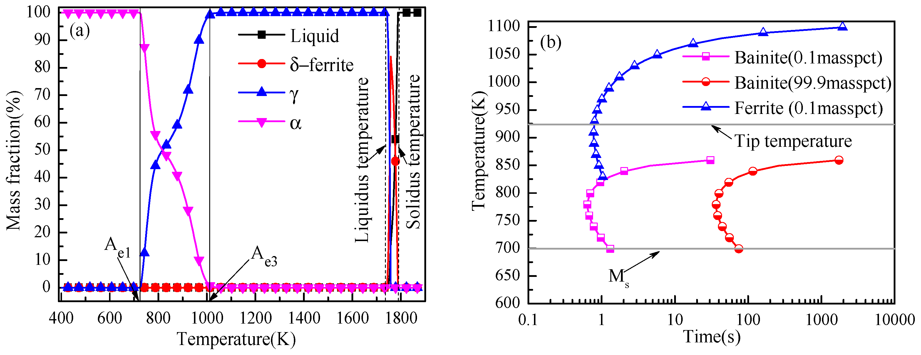
Figure 3.
Schematic of forging process and isothermal heat treatment of specimens.
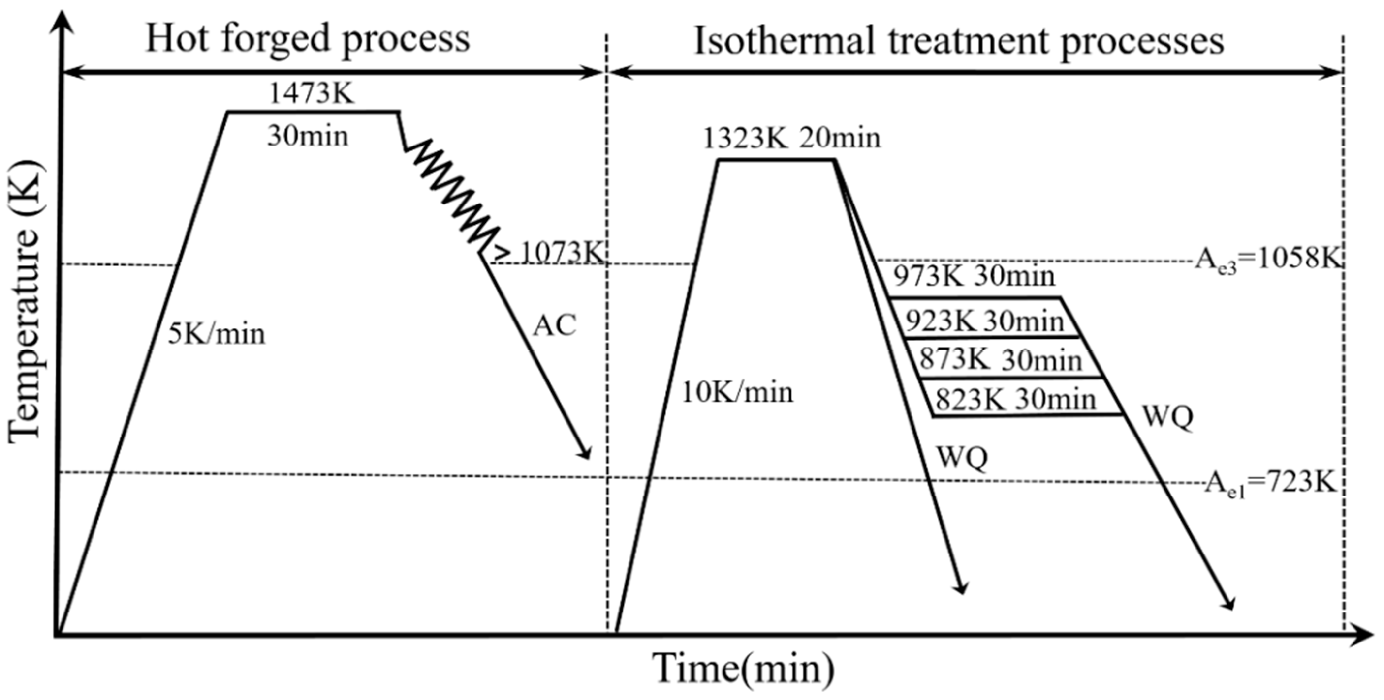
Figure 4.
Morphology and composition of typical inclusions. (a) MgO–Al2O3; (b) MgO–Al2O3-TiO2; (c) MgO–Al2O3–TiO2–TiN; (d) MgO–Al2O3–TiO2–TiN–MnS.
Figure 4.
Morphology and composition of typical inclusions. (a) MgO–Al2O3; (b) MgO–Al2O3-TiO2; (c) MgO–Al2O3–TiO2–TiN; (d) MgO–Al2O3–TiO2–TiN–MnS.
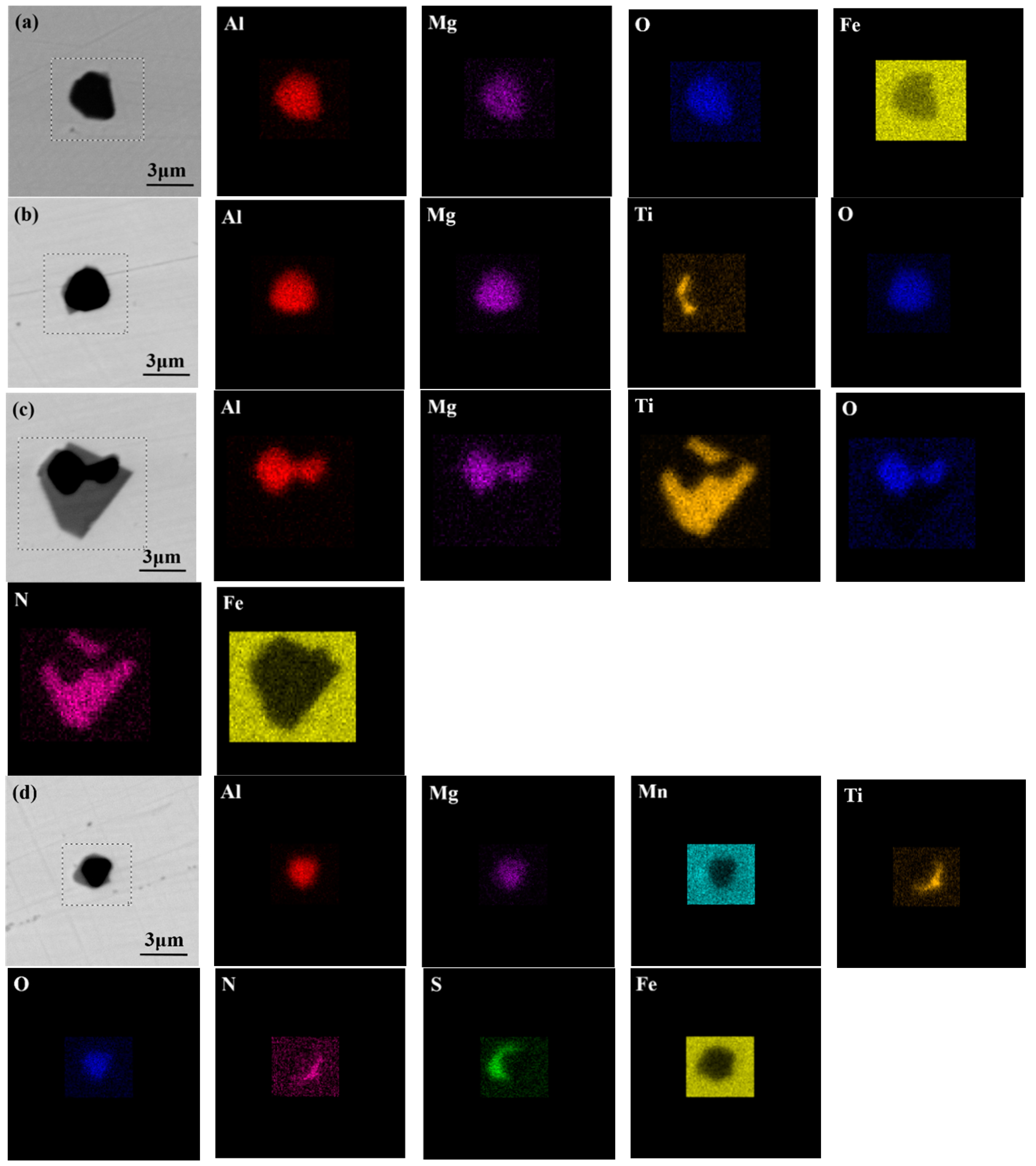
Figure 5.
Size distributions of oxide inclusions in experimental steels.

Figure 6.
Optical micrograph of experimental steels. (a) Initial microstructure of steels after forging, and (b) prior austenite grain micrograph of experimental steels quenched at 1323 K (1050 °C).
Figure 6.
Optical micrograph of experimental steels. (a) Initial microstructure of steels after forging, and (b) prior austenite grain micrograph of experimental steels quenched at 1323 K (1050 °C).

Figure 7.
Typical microstructure of the specimens. (a) M1, (b) M2, (c) M3, and (d) M4.

Figure 8.
X-ray diffraction curves of the specimens.
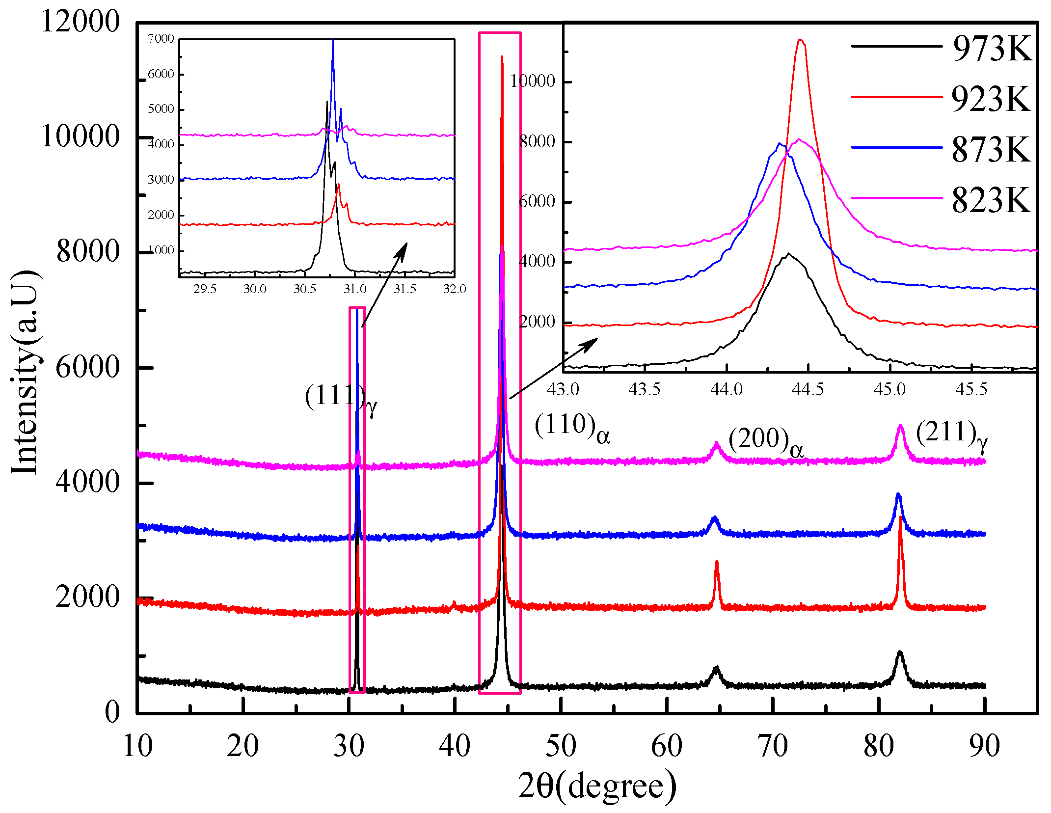
Figure 9.
Morphologies of intragranular acicular ferrite (IAF) induced by inclusions for different specimens. (a) M1, (b) M2, (c) M3, and (d) M4.
Figure 9.
Morphologies of intragranular acicular ferrite (IAF) induced by inclusions for different specimens. (a) M1, (b) M2, (c) M3, and (d) M4.

Figure 10.
SEM mapping images of inclusion nucleating IAF in M3.

Figure 11.
Variation of macrohardness and the Charpy absorbed energy at room temperature.

Figure 12.
Fracture morphology features of specimens. (a–c) M1; (d–f) M2; (g–i) M3; and (j–l) M4.
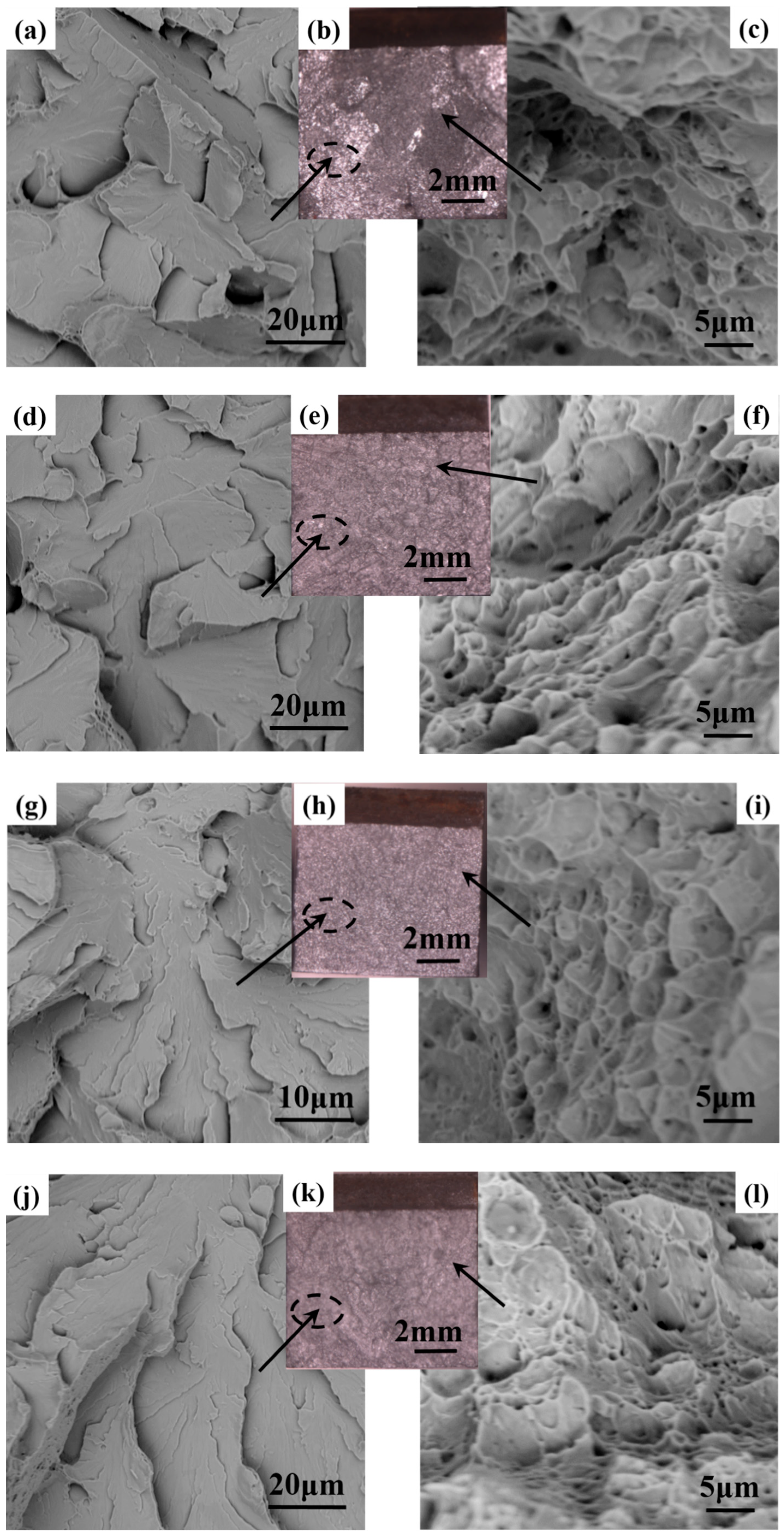
Figure 13.
SEM images of the fibrous region on the fracture surface of the inclusion in M3.

Figure 14.
Phase transformation of inclusions in steel cooled from 1900 to 800 K.

Figure 15.
Model of IAF formation on the surface of a spherical inclusion. (a) Nucleation of IAF on the surface of inclusion, and (b) the actual SEM image of IAF nucleated on inclusion.
Figure 15.
Model of IAF formation on the surface of a spherical inclusion. (a) Nucleation of IAF on the surface of inclusion, and (b) the actual SEM image of IAF nucleated on inclusion.

Figure 16.
Effect of the value of r/R on energy barrier to ferrite at inclusions.

Figure 17.
Relationship between the driving force and the temperature of the ferrite formation.

Figure 18.
Schematic illustration of the refinement mechanism of the microstructure at different heat-treatment temperatures.
Figure 18.
Schematic illustration of the refinement mechanism of the microstructure at different heat-treatment temperatures.


Table 1.
Chemical composition of experimental steel (wt. %).
| C | Si | Mn | Nb | Ti | Ni | Al | S | N |
|---|---|---|---|---|---|---|---|---|
| 0.09 | 0.38 | 1.58 | 0.04 | 0.01 | 0.25 | 0.025 | 0.008 | 0.003 |
Table 2.
Mechanical properties of specimens.
| Specimen | Yield Strength (MPa) | Tensile Strength (Mpa) | Elongation (%) |
|---|---|---|---|
| M1 | 535 | 769 | 9.6 |
| M2 | 529 | 763 | 10.8 |
| M3 | 531 | 803 | 13.6 |
| M4 | 540 | 775 | 8.4 |
© 2018 by the authors. Licensee MDPI, Basel, Switzerland. This article is an open access article distributed under the terms and conditions of the Creative Commons Attribution (CC BY) license (http://creativecommons.org/licenses/by/4.0/).
Share and Cite
MDPI and ACS Style
Zhou, Y.; Yang, S.; Li, J.; Liu, W.; Dong, A. Effects of Heat-Treatment Temperature on the Microstructure and Mechanical Properties of Steel by MgO Nanoparticle Additions. Materials 2018, 11, 1707. https://doi.org/10.3390/ma11091707
AMA Style
Zhou Y, Yang S, Li J, Liu W, Dong A. Effects of Heat-Treatment Temperature on the Microstructure and Mechanical Properties of Steel by MgO Nanoparticle Additions. Materials. 2018; 11(9):1707. https://doi.org/10.3390/ma11091707
Chicago/Turabian StyleZhou, Yutao, Shufeng Yang, Jingshe Li, Wei Liu, and Anping Dong. 2018. "Effects of Heat-Treatment Temperature on the Microstructure and Mechanical Properties of Steel by MgO Nanoparticle Additions" Materials 11, no. 9: 1707. https://doi.org/10.3390/ma11091707
Note that from the first issue of 2016, this journal uses article numbers instead of page numbers. See further details here.