One-Shot Drilling Analysis of Stack CFRP/UNS A92024 Bonding by Adhesive


Abstract
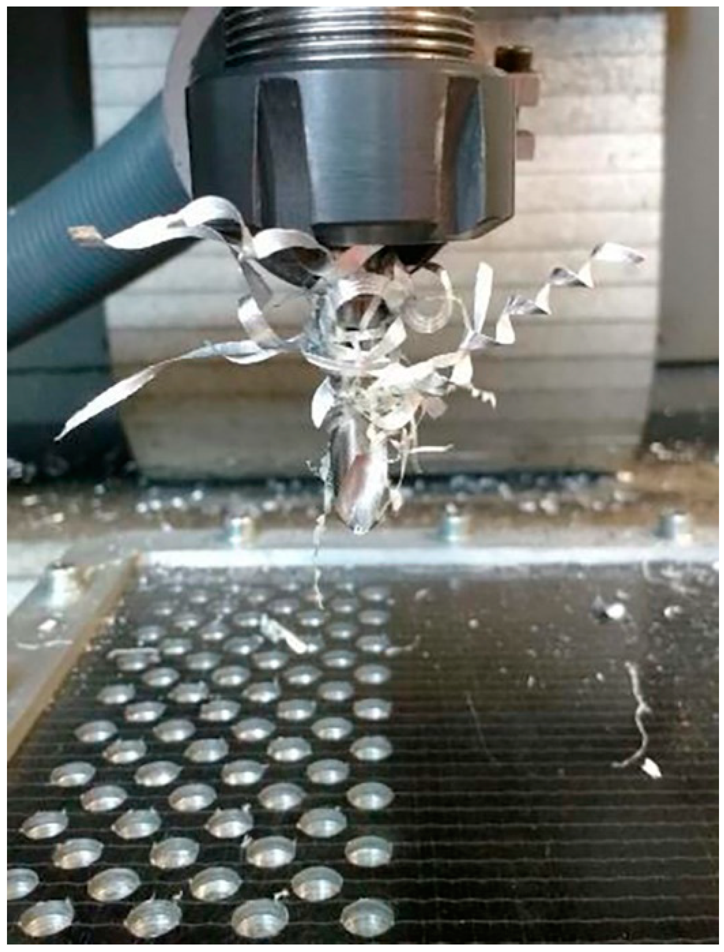
:1. Introduction
2. Materials and Methods
3. Results and Discussion
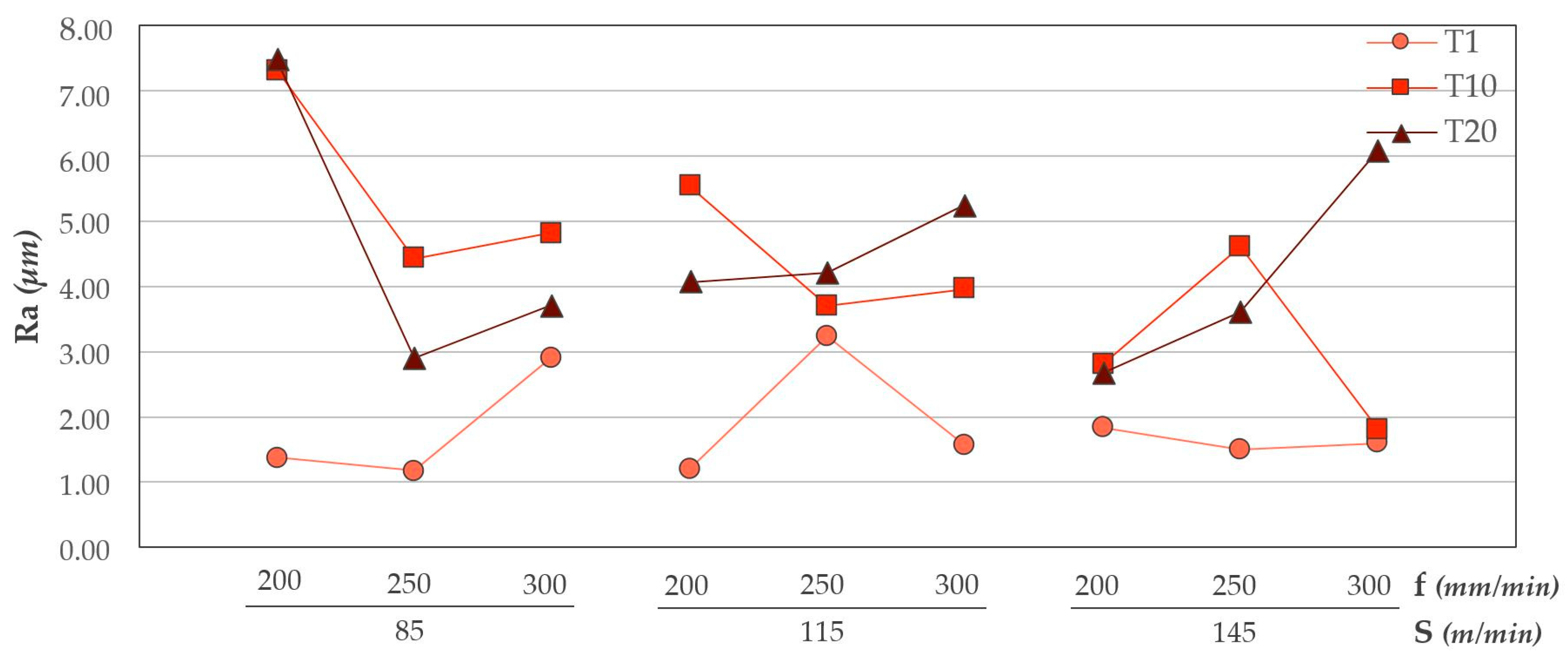
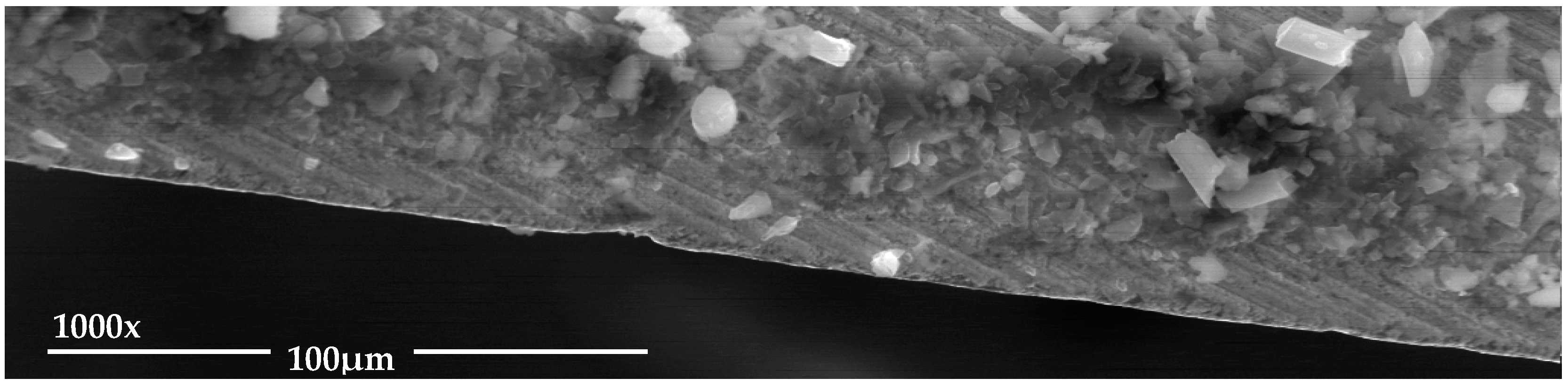
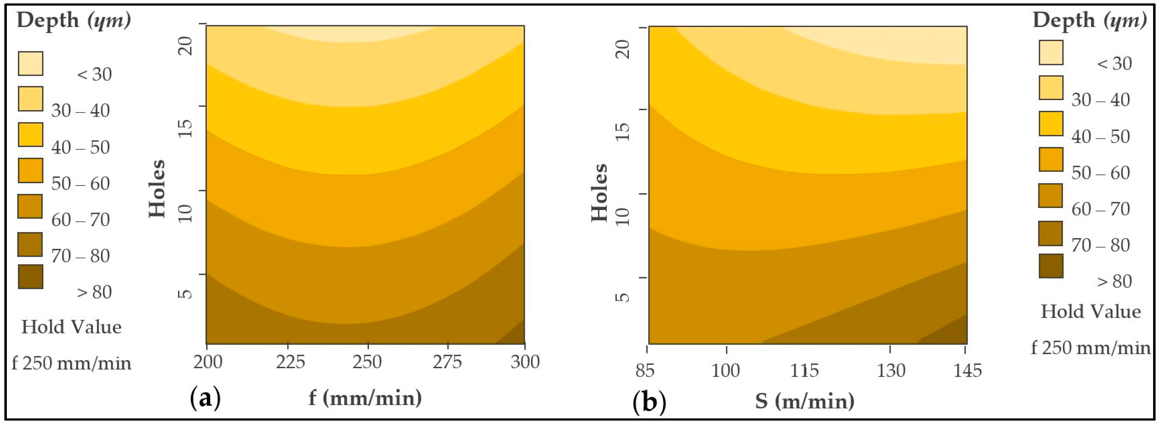
3.1. Surface Quality
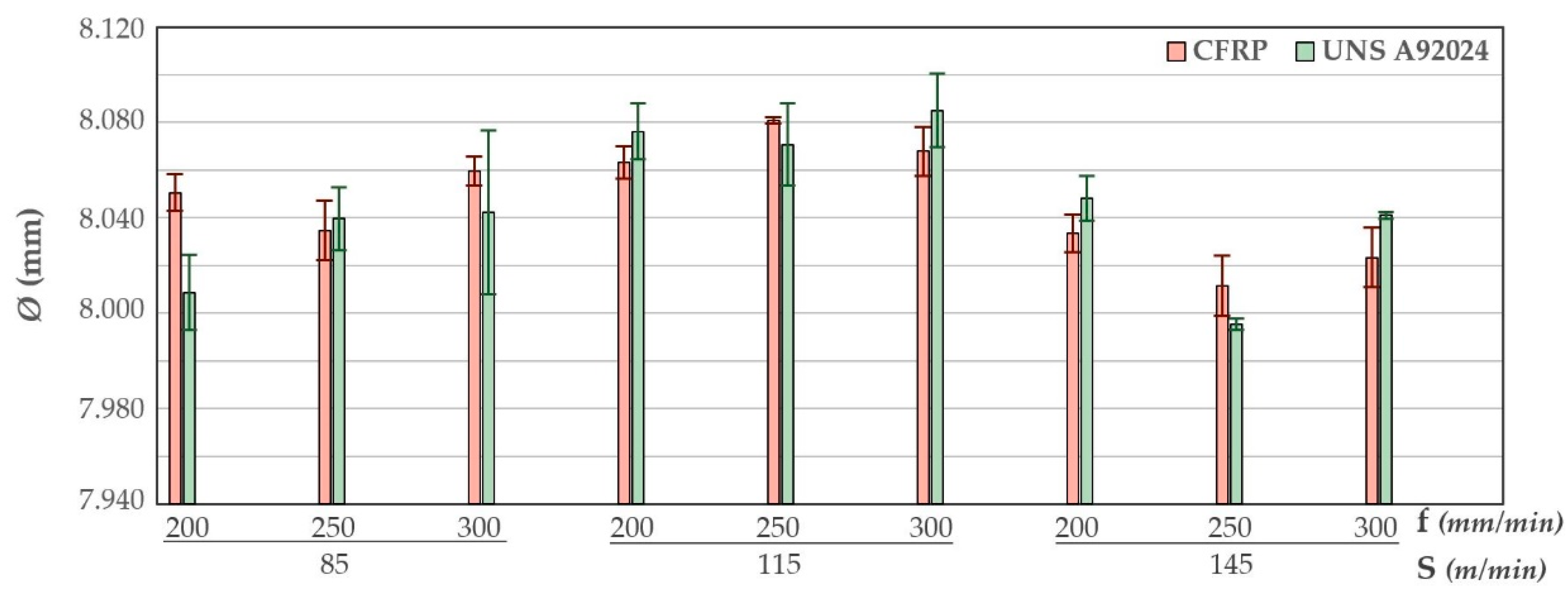
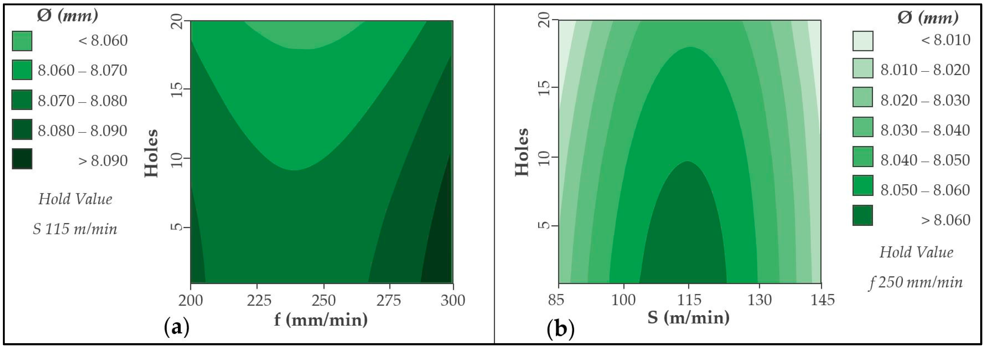
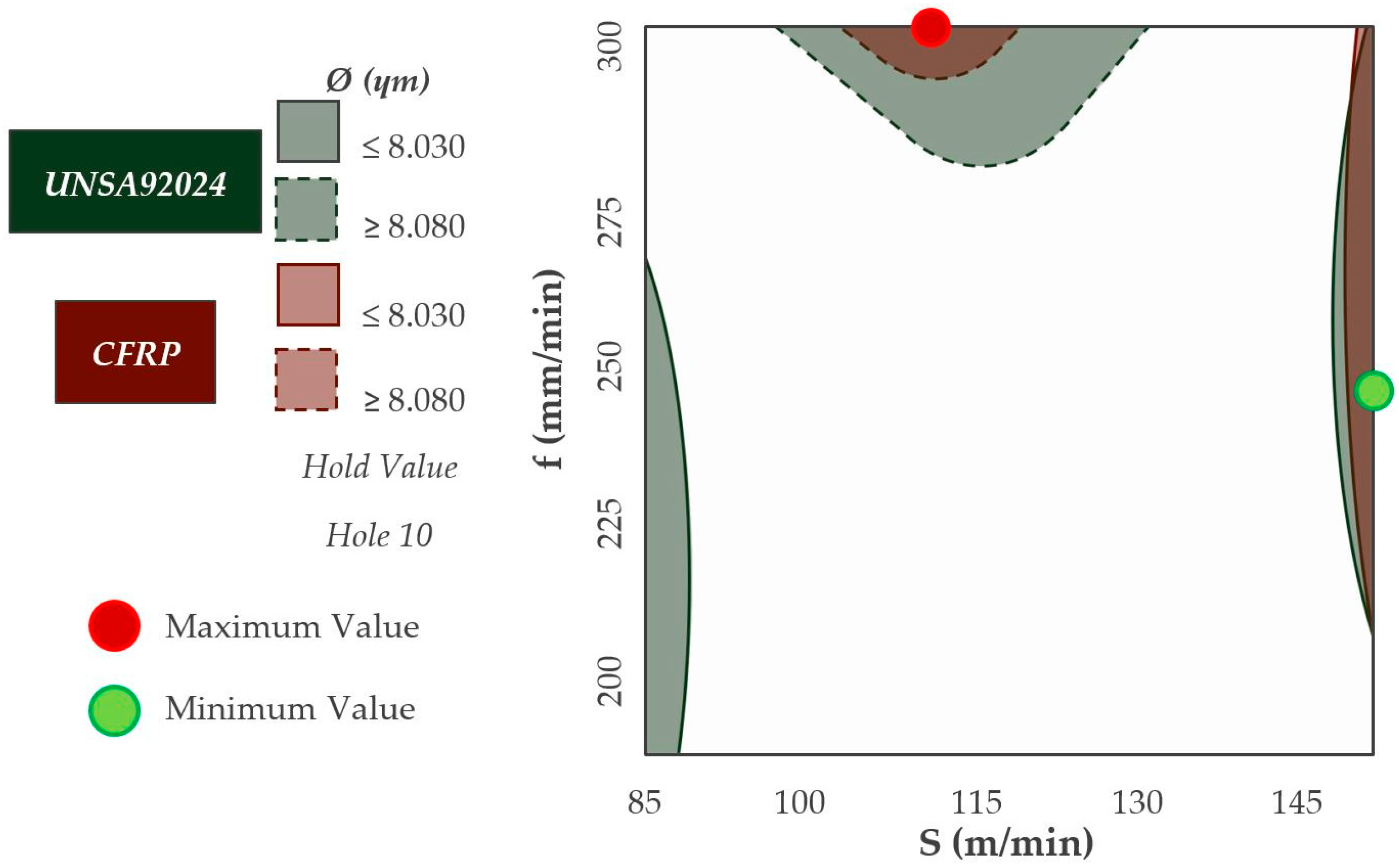
3.2. Diameters
3.3. Adhesive
4. Conclusions
Author Contributions
Funding
Acknowledgments
Conflicts of Interest
References
- Cirillo, P.; Marino, A.; Natale, C.; Di Marino, E.; Chiacchio, P.; De Maria, G. A low-cost and flexible solution for one-shot cooperative robotic drilling of aeronautic stack materials. IFAC PapersOnLine 2017, 50, 4602–4609. [Google Scholar] [CrossRef]
- Gómez-Parra, A.; Álvarez-Alcón, M.; Salguero, J.; Batista, M.; Marcos, M. Analysis of the evolution of the built-up edge and built-up layer formation mechanisms in the dry turning of aeronautical aluminium alloys. Wear 2013, 302, 1209–1218. [Google Scholar] [CrossRef]
- Wang, C.-Y.; Chen, Y.-H.; An, Q.-L.; Cai, X.-J.; Ming, W.-W.; Chen, M. Drilling temperature and hole quality in drilling of CFRP/aluminum stacks using diamond coated drill. Int. J. Precis. Eng. Manuf. 2015, 16, 1689–1697. [Google Scholar] [CrossRef]
- Zitoune, R.; Krishnaraj, V.; Collombet, F. Study of drilling of composite material and aluminium stack. Compos. Struct. 2010, 92, 1246–1255. [Google Scholar] [CrossRef]
- Nagaraja, R.; Rangaswamy, T. Drilling of CFRP and GFRP composite laminates using one shot solid carbide step drill K44. AIP Conf. Proc. 2018, 020025. [Google Scholar] [CrossRef]
- Salguero, J.; Ponce, M.B.; Fernandez-Vidal, S.R.; Mayuet, P.; Rosales, E.I.; Marcos, M. Cutting Speed and Feedrate Based Analysis of Cutting Forces in the One Shot Drilling (OSD) of CFRC/Al Hybrid Stacks. In Proceedings of the Volume 2B: Advanced Manufacturing; ASME: Montreal, QC, Canada, 2014; Paper No. IMECE2014-38027; p. V02BT02A057. 7p, ISBN 978-0-7918-4644-5. [Google Scholar] [CrossRef]
- Fernández-Vidal, S.R.; Mayuet, P.; Rivero, A.; Salguero, J.; Del Sola, I.; Marcos, M. Analysis of the effects of tool wear on dry helical milling of Ti6Al4V alloy. Procedia Eng. 2015, 132, 593–599. [Google Scholar] [CrossRef]
- Lawcock, G.; Ye, L.; Mai, Y.; Sun, C. The effect of adhesive bonding between aluminum and composite prepreg on the mechanical properties of carbon-fiber- reinforced metal laminates. Compos. Sci. Technol. 2006, 57, 35–45. [Google Scholar] [CrossRef]
- Cano, R.J.; Loos, A.C.; Jensen, B.J.; Britton, S.M.; Tuncol, G.; Long, K. Epoxy/glass and polyimide (LaRC PETI-8)/carbon fiber metal laminates made by the VARTM process. SAMPE J. 2011, 47, 50–58. [Google Scholar]
- Huang, Z.; Sugiyama, S.; Yanagimoto, J. Adhesive-embossing hybrid joining process to fiber-reinforced thermosetting plastic and metallic thin sheets. Procedia Eng. 2014, 81, 2123–2128. [Google Scholar] [CrossRef]
- Martinsen, K.; Hu, S.J.; Carlson, B.E. Joining of dissimilar materials. CIRP Ann. Manuf. Technol. 2015, 64, 679–699. [Google Scholar] [CrossRef] [Green Version]
- Samaei, M.; Zehsaz, M.; Chakherlou, T.N. Experimental and numerical study of fatigue crack growth of aluminum alloy 2024-T3 single lap simple bolted and hybrid (adhesive/bolted) joints. Eng. Fail. Anal. 2016, 59, 253–268. [Google Scholar] [CrossRef]
- Higgins, A. Adhesive bonding of aircraft structures. Int. J. Adhes. Adhes. 2000, 20, 367–376. [Google Scholar] [CrossRef]
- Zhang, K.; Yang, Z.; Li, Y. A method for predicting the curing residual stress for CFRP/Al adhesive single-lap joints. Int. J. Adhes. Adhes. 2013, 46, 7–13. [Google Scholar] [CrossRef]
- Kuo, C.L.; Soo, S.L.; Aspinwall, D.K.; Carr, C.; Bradley, S.; M’Saoubi, R.; Leahy, W. Development of single step drilling technology for multilayer metallic-composite stacks using uncoated and PVD coated carbide tools. J. Manuf. Process. 2018, 31, 286–300. [Google Scholar] [CrossRef]
- Ashrafi, S.A.; Sharif, S.; Farid, A.A.; Yahya, M. Performance evaluation of carbide tools in drilling CFRP-Al stacks. J. Compos. Mater. 2013, 48, 2071–2084. [Google Scholar] [CrossRef]
- D’Orazio, A.; El Mehtedi, M.; Forcellese, A.; Nardinocchi, A.; Simoncini, M. Tool wear and hole quality in drilling of CFRP/AA7075 stacks with DLC and nanocomposite TiAlN coated tools. J. Manuf. Process. 2017, 30, 582–592. [Google Scholar] [CrossRef]
- Krishnaraj, V.; Prabukarthi, A.; Ramanathan, A.; Elanghovan, N.; Kumar, M.S.; Zitoune, R.; Davim, J.P. Optimization of machining parameters at high speed drilling of carbon fiber reinforced plastic (CFRP) laminates. Compos. Part. B Eng. 2012, 43, 1791–1799. [Google Scholar] [CrossRef]
- Giasin, K.; Ayvar-Soberanis, S.; Hodzic, A. Evaluation of cryogenic cooling and minimum quantity lubrication effects on machining GLARE laminates using design of experiments. J. Clean. Prod. 2016, 135, 533–548. [Google Scholar] [CrossRef]
- Kuo, C.; Li, Z.; Wang, C. Multi-objective optimisation in vibration-assisted drilling of CFRP/Al stacks. Compos. Struct. 2017, 173, 196–209. [Google Scholar] [CrossRef]
- Wang, H.; Sun, J.; Li, J.; Lu, L.; Li, N. Evaluation of cutting force and cutting temperature in milling carbon fiber-reinforced polymer composites. Int. J. Adv. Manuf. Technol. 2016, 82, 1517–1525. [Google Scholar] [CrossRef]
- Kyratsis, P.; Markopoulos, A.; Efkolidis, N.; Maliagkas, V.; Kakoulis, K. Prediction of thrust force and cutting torque in drilling based on the response surface methodology. Machines 2018, 6, 24. [Google Scholar] [CrossRef]
- Uddin, M.; Basak, A.; Pramanik, A.; Singh, S. Evaluating hole quality in drilling of Al 6061 alloys. Materials 2018, 11, 2443. [Google Scholar] [CrossRef] [PubMed]
- Bleicher, F.; Wiesinger, G.; Kumpf, C.; Finkeldei, D.; Baumann, C.; Lechner, C. Vibration assisted drilling of CFRP/metal stacks at low frequencies and high amplitudes. Prod. Eng. 2018, 12, 289–296. [Google Scholar] [CrossRef] [Green Version]
- Jallageas, J.; K’Nevez, J.Y.; Chérif, M.; Cahuc, O. Modeling and optimization of vibration-assisted drilling on positive feed drilling unit. Int. J. Adv. Manuf. Technol. 2013, 67, 1205–1216. [Google Scholar] [CrossRef]
- Sorrentino, L.; Turchetta, S.; Bellini, C. In process monitoring of cutting temperature during the drilling of FRP laminate. Compos. Struct. 2017, 168, 549–561. [Google Scholar] [CrossRef]


 | |||||||||
|---|---|---|---|---|---|---|---|---|---|
| DC (mm) | LU (mm) | DCON (mm) | SIG (°) | PL (mm) | OAL (mm) | LF (mm) | LCF (mm) | Helix Angle (°) | Material |
| 7.92 | 25.00 | 8.00 | 118.00 140.00 | 1.20 | 80.00 | 78.80 | 30.00 | 29.82 | Carbidre Substrate Uncoated |
| Orientation (°) | Reinforcement | Matrix | Tensile Strength (MPa) | ILSS (MPa) | Tg (°C) |
|---|---|---|---|---|---|
| 0/90 | DowAksa A42 carbon fiber 49 Vol % | Epoxy DOW Voraforce 5300 51 Vol % | 871 | 52 | 121 |
| Composition | Density (g/cc) | Ultimate Tensile Strength (Mpa) | Yield Tensile Strength (Mpa) | Elongation at Break (%) | Modulus of Elasticity (GPa) |
|---|---|---|---|---|---|
| Al 90.7–94.7%, Cu 3.8–4.9%, Mg 1.2–1.8%, Mn 0.30–0.90%, Zn 0.25%, Ti 0.15%, other 0.15% | 2.78 | 425 | 310 | ≥10 | 73.1 |
| Polymerization | Operating Temperature (°C) | Tg (°C) | Elongation at Break (%) | Fixture Time (min) | Full Cure (h) | Lap Shear Strength (MPa) | Tensile Strength at Break (MPa) | Tensile Modulus (MPa) |
|---|---|---|---|---|---|---|---|---|
| Room Temp. | −40/150 | 86 | 50 | 120 | 24 | 16 | 8–10 | 180 |
| Trial | S (m/min) | f (mm/min) | Holes Machined 1 | Lubrication |
|---|---|---|---|---|
| 1 | 85 | 200 | 20 | Dry |
| 2 | 85 | 250 | 20 | Dry |
| 3 | 85 | 300 | 20 | Dry |
| 4 | 115 | 200 | 20 | Dry |
| 5 | 115 | 250 | 20 | Dry |
| 6 | 115 | 300 | 20 | Dry |
| 7 | 145 | 200 | 20 | Dry |
| 8 | 145 | 250 | 20 | Dry |
| 9 | 145 | 300 | 20 | Dry |
| Trial | Hole | Ø [mm (±µm)] | Ra [µm (±µm)] | Depth [µm (±µm)] | ||
|---|---|---|---|---|---|---|
| CFRP | Al | CFRP | Al | Adhesive | ||
| 1 | 1 | 8.031 (±0.816) | 8.042 (±0.408) | 1.38 (±0.033) | 1.62 (±0.065) | 42.584 (±0.781) |
| 10 | 7.998 (±1.225) | 8.050 (±0.816) | 7.32 (±0.033) | 6.23 (±0.041) | 27.136 (±0.887) | |
| 20 | 7.998 (±0.408) | 8.060 (±0.002) | 7.47 (±0.024) | 12.22 (±0.139) | 44.910 (±0.678) | |
| 2 | 1 | 8.026 (±0.816) | 8.022 (±1.633) | 1.18 (±0.065) | 2.71 (±0.163) | 24.730 (±0.906) |
| 10 | 8.036 (±2.041) | 8.052 (±1.225) | 4.43 (±0.065) | 7.35 (±0.163) | 33.924 (±0.746) | |
| 20 | 8.057 (±0.408) | 8.031 (±0.408) | 2.90 (±0.098) | 4.53 (±0.122) | 23.937 (±0.737) | |
| 3 | 1 | 8.052 (±0.408) | 8.062 (±1.225) | 2.92 (±0.049) | 3.20 (±0.114) | 21.322 (±0.431) |
| 10 | 8.079 (±0.816) | 8.066 (±1.225) | 4.82 (±0.057) | 5.40 (±0.220) | 29.644 (±0.707) | |
| 20 | 7.997 (±1.225) | 8.052 (±1.225) | 3.72 (±0.147) | 4.97 (±0.147) | 10.351 (±0.687) | |
| 4 | 1 | 8.077 (±1.225) | 8.055 (±1.225) | 1.20 (±0.122) | 3.58 (±0.147) | 53.363 (±0.296) |
| 10 | 8.091 (±0.408) | 8.071 (±0.816) | 5.53 (±0.008) | 3.57 (±0.204) | 35.714 (±0.485) | |
| 20 | 8.062 (±1.225) | 8.064 (±1.633) | 4.06 (±0.147) | 3.68 (±0.131) | 47.633 (±0.892) | |
| 1 | 8.095 (±2.449) | 8.082 (±1.633) | 3.23 (±0.016) | 4.82 (±0.057) | 54.542 (±0.532) | |
| 5 | 10 | 8.059 (±0.408) | 8.079 (±0.816) | 3.71 (±0.114) | 6.06 (±0.122) | 59.167 (±0.558) |
| 20 | 8.059 (±1.289) | 8.081 (±0.816) | 4.21 (±0.041) | 7.98 (±0.090) | 51.512 (±0.401) | |
| 1 | 8.100 (±1.633) | 8.054 (±2.449) | 1.57 (±0.024) | 4.04 (±0.073) | 39.640 (±0.719) | |
| 6 | 10 | 8.091 (±0.816) | 8.071 (±0.408) | 3.96 (±0.220) | 5.28 (±0.139) | 66.190 (±0.441) |
| 20 | 8.064 (±0.816) | 8.079 (±0.816) | 5.25 (±0.106) | 6.66 (±0.033) | 30.546 (±0.552) | |
| 7 | 1 | 8.062 (±1.225) | 8.037 (±0.408) | 1.84 (±0.090) | 2.28 (±0.049) | 70.171 (±0.474) |
| 10 | 8.043 (±0.816) | 8.041 (±0.816) | 2.81 (±0.057) | 2.38 (±0.163) | 62.413 (±0.550) | |
| 20 | 8.040 (±1.633) | 8.023 (±0.408) | 2.67 (±0.155) | 2.58 (±0.090) | 50.236 (±0.575) | |
| 8 | 1 | 7.997 (±1.225) | 7.994 (±1.225) | 1.50 (±0.016) | 5.12 (±0.090) | 78.464 (±0.495) |
| 10 | 7.992 (±1.633) | 8.020 (±2.449) | 4.61 (±0.024) | 6.15 (±0.139) | 82.222 (±0.603) | |
| 20 | 7.998 (±0.408) | 8.021 (±0.816) | 3.61 (±0.180) | 6.19 (±0.057) | 72.189 (±0.612) | |
| 9 | 1 | 8.041 (±0.408) | 8.006 (±1.633) | 1.59 (±0.016) | 6.09 (±0.171) | 61.680 (±0.457) |
| 10 | 8.043 (±0.816) | 8.035 (±1.225) | 1.82 (±0.057) | 5.76 (±0.163) | 108.765 (±0.257) | |
| 20 | 8.040 (±1.225) | 8.030 (±0.408) | 6.08 (±0.106) | 6.94 (±0.057) | 80.120 (±0.596) | |
| Source | DF | Adj SS | Adj MS | F-Value | P-Value |
|---|---|---|---|---|---|
| CFRP | |||||
| S (m/min) | 1 | 5.1554 | 5.1554 | 2.65 | 0.122 |
| f (mm/min) | 1 | 0.3655 | 0.3655 | 0.19 | 0.670 |
| Drills | 1 | 30.8374 | 30.8374 | 15.88 | 0.001 |
| Error | 17 | 33.0218 | 1.9425 | ||
| Total | 26 | 83.1892 | |||
| UNS A92024 | |||||
| S (m/min) | 1 | 1.416 | 1.4164 | 0.53 | 0.478 |
| f (mm/min) | 1 | 5.606 | 5.6057 | 2.08 | 0.167 |
| Drills | 1 | 27.602 | 27.6024 | 10.26 | 0.005 |
| Error | 17 | 45.741 | 2.6906 | ||
| Total | 26 | 127.240 | |||
| Source | DF | Adj SS | Adj MS | F-Value | P-Value |
|---|---|---|---|---|---|
| CFRP | |||||
| S (m/min) | 01 | 0.002912 | 0.002912 | 17.56 | 0.001 |
| f (mm/min) | 01 | 0.000008 | 0.000008 | 0.05 | 0.834 |
| Drills | 01 | 0.000425 | 0.000425 | 2.57 | 0.128 |
| Error | 17 | 0.002818 | 0.000166 | ||
| Total | 26 | 0.014807 | |||
| UNS A92024 | |||||
| S (m/min) | 01 | 0.000017 | 0.000017 | 0.03 | 0.863 |
| f (mm/min) | 01 | 0.000616 | 0.000616 | 1.11 | 0.307 |
| Drills | 01 | 0.001531 | 0.001531 | 2.76 | 0.115 |
| Error | 17 | 0.009441 | 0.000555 | ||
| Total | 26 | 0.028340 |
| Source | DF | Adj SS | Adj MS | F-Value | P-Value |
|---|---|---|---|---|---|
| ADHESIVE | |||||
| Model | 9 | 11168.5 | 1240.94 | 9.22 | 0.000 |
| S (m/min) | 1 | 16.6 | 16.6 | 0.12 | 0.730 |
| f (mm/min | 1 | 68.1 | 68.06 | 0.51 | 0.487 |
| Drills | 1 | 9235.4 | 9235.4 | 68.60 | 0.000 |
| S (m/min) *Drills | 1 | 1225.5 | 1225.47 | 9.10 | 0.008 |
| Error | 17 | 2288.6 | 134.62 | ||
| Total | 26 | 13457.1 |
© 2019 by the authors. Licensee MDPI, Basel, Switzerland. This article is an open access article distributed under the terms and conditions of the Creative Commons Attribution (CC BY) license (http://creativecommons.org/licenses/by/4.0/).
Share and Cite
Bañon, F.; Sambruno, A.; Fernandez-Vidal, S.; Fernandez-Vidal, S.R. One-Shot Drilling Analysis of Stack CFRP/UNS A92024 Bonding by Adhesive. Materials 2019, 12, 160. https://doi.org/10.3390/ma12010160
Bañon F, Sambruno A, Fernandez-Vidal S, Fernandez-Vidal SR. One-Shot Drilling Analysis of Stack CFRP/UNS A92024 Bonding by Adhesive. Materials. 2019; 12(1):160. https://doi.org/10.3390/ma12010160
Chicago/Turabian StyleBañon, Fermin, Alejandro Sambruno, Sergio Fernandez-Vidal, and Severo Raul Fernandez-Vidal. 2019. "One-Shot Drilling Analysis of Stack CFRP/UNS A92024 Bonding by Adhesive" Materials 12, no. 1: 160. https://doi.org/10.3390/ma12010160
APA StyleBañon, F., Sambruno, A., Fernandez-Vidal, S., & Fernandez-Vidal, S. R. (2019). One-Shot Drilling Analysis of Stack CFRP/UNS A92024 Bonding by Adhesive. Materials, 12(1), 160. https://doi.org/10.3390/ma12010160