Anti-Corrosion Property of Glass Flake Reinforced Chemically Bonded Phosphate Ceramic Coatings


1
School of Civil Engineering and Architecture, Wuhan University of Technology, Wuhan 430070, China
2
State Key Laboratory for Disaster Prevention & Mitigation of Explosion & Impact, Army Engineering University, Nanjing 210007, China
3
State Key Laboratory of Silicate Materials for Architectures, Wuhan University of Technology, Wuhan 430070, China
*
Author to whom correspondence should be addressed.
Materials 2019, 12(13), 2082; https://doi.org/10.3390/ma12132082
Submission received: 23 May 2019
/
Revised: 26 June 2019
/
Accepted: 26 June 2019
/
Published: 28 June 2019
(This article belongs to the Special Issue Sustainable Designed Pavement Materials)
Abstract
:Glass flake (GF) was used as the reinforcement in chemically bonded phosphate ceramic (CBPC) coatings to promote anti-corrosion property. The crystalline phase, curing behavior, micromorphology and electrochemical performance of the coatings were studied. The results indicate that with the addition of magnesia (MgO), a new bonding phase (Mg3(PO4)2) can be formed, which can help the CBPCs achieve a more compact and denser structure. The effect of the magnesia and the GF additives on curing behavior is obvious: the heat of reaction of the phosphate ceramic materials increases with the addition of the magnesia and the GF, which emphasizes the higher crosslinking density in the phosphate ceramic materials. The phosphate ceramic coatings with the magnesia have a higher impedance value compared with the neat phosphate ceramic coating, while the highest impedance value is obtained with increased content of GF. The corrosion mechanism is mainly contributed by the new bonding phase and GF particles, which can hinder the permeation pathway and make the permeation more circuitous.
1. Introduction
Reinforced concrete (RC) is one of the most commonly used modern construction materials. The corrosion of the interface between concrete and steel rebar affects the service life of RC seriously. In the past decades, in order to increase the lifespan of RC, researchers have dedicated efforts towards the enhancement of bond strength and corrosion resistance in RC [1,2]. Among all the anti-corrosion technology, a most effective way to improve the property of corrosion resistance is to cover the rebar with a durable and adhesive coating [3], which can be divided into organic coatings and inorganic coatings. Epoxy [4,5] and modified resin [6] have been generally adopted as organic coatings, while inorganic coatings include galvanizing metal coatings [7], chemically reactive enamel (CRE) coatings [8], and chemically bonded phosphate ceramic (CBPC) coatings [9]. In the application of the epoxy coating in reinforced concrete, Brown MC [10] arrived at the conclusion that the durability of the steel with the epoxy coating was not ideal due to the moisture that penetrates beneath the coating, which means that the epoxy-coated steel has a higher corrosion rate than bare steel. What’s more, the bone strength loss between the epoxy-coated steel and the concrete reached 20% compared to bare rebar [11]. For the inorganic coatings, a weakening effect on the bond strength between the galvanized reinforcing steel and the concrete was observed due to hydrogen evolution at the interface [12]. A high temperature of 800 °C needs to be applied to the chemically reactive enamel-coated steel, which can lead to a reduction in the creep limit and strength [1].
In recent years, more and more studies have focused on the utilization of CBPCs, which are derived from the reactions between base and acid, such as the metal oxide (Al2O3, MgO) and the soluble acid phosphate (KH2PO4, Al(H2PO4)3) [13,14]. Due to their corrosion resistance, mechanical resistance, thermal conductivity and low temperature used in their processing, CBPC coatings have considerable technological importance [15]. CBPC coatings can be seen to use the phosphate matrixes as the binding phases and the metal oxides as suitable fillers. Researchers [16,17,18] have investigated the influence of ceramic oxides (AlN, MgO, and ZrO2) on the improvement of the thermal properties of CBPC coatings. The abrasive filler of Al2O3-SiC in aluminum phosphate has been produced to enhance the abrasion resistance of coatings [19]. The ceramic coatings of aluminum phosphate formed by the reaction between soluble acid phosphates and alumina and alumina–sol–gel systems was studied [20]. H.M. Hawthorne et al. [21] prepared phosphate ceramic coatings on stainless steel substrates and analyzed the mechanical performance and electrochemical property. The application by thermal spraying for binders was carried out, and the microstructure defects of the coatings were improved [22]. A series of CBPC coatings were applied to steel surfaces to reduce or eliminate corrosion [23]. Da Bian et al. [24] paid attention to graphene-reinforced CBPC coatings. Zhu Ding et al. [25] studied the mechanical characterization and microstructure of CBPC composites reinforced with fiber, prepared at room temperature.
Glass flake (GF) particles are inorganic platelets with excellent resistance to chemicals and aging. Many efforts have been focused towards corrosion-resistant coatings with the advanced barrier properties of GF [26,27,28,29,30], and the parallel and overlapped arrangement of GF particles could form a compact impermeable layer in organic coatings. There are microstructure defects between GF particles and the organic coating matrix due to the coating matrix belonging to organic material, while GF belongs to inorganic materials; thus, we can only effectively improve the permeability resistance of organic coatings by surface treatment and functionalization of GF particles.
In all cases cited, there have been few reports on the application of GF particles as fillers in CBPC coatings. Meanwhile, the anticorrosion mechanism of the GF-reinforced CBPC coatings also needs to be illustrated. In this study, CBPC coatings reinforced with GF particles were prepared in order to protect the round steel. The crystalline phase, curing behavior, and micromorphology of the CBPC-based ceramic materials were analyzed, and the electrochemical characterization of the CBPC coatings was carried out in 3.5 wt.% NaCl solution using electrochemical measurement. Furthermore, the anticorrosion mechanism of the coating was also investigated.
2. Materials and Methods
2.1. Materials
The CBPC coatings reinforced with GF were applied onto round steel 8 mm in diameter and 20 mm in length by mixing raw materials of phosphate ceramic materials as shown in Table 1.
The preparation of monoaluminium phosphate (MAP) binder is based on the reaction between aluminum hydroxide and phosphoric acid at 120 °C under constant stirring for 60 min. The quantities were calculated according to Equation (1). For the preparation of MAP binder, 135.1 g of pure water were used to dilute 345.9 g of 85% phosphoric acid to 60%, and then 78.0 g of aluminum hydroxide were added.
3H3PO4 + Al(OH)3 → Al(H2PO4)3 + 3H2O
The mixture proportion of phosphate ceramic coating materials are shown in Table 2. The coated samples were prepared by brush coating with a clean bristle brush. Before preparing coating, 800 grit silicon carbide abrasive papers were used to polish the surface of the round steel, the round steel was degreased in acetone for 15 min (in ultrasonic bath) and then rinsed with deionized water. The coated round steel was placed at room temperature (25 ± 1 °C) for 10 h and then heated in an electric oven according to the curing process as shown in Figure 1.
2.2. Characterization
Laser scanning confocal microscopy (LSCM, manufacture, Oberkochen, Germany) was used to characterize the thickness and surface topography of GF. The thickness of the coating was tested using a QNIX4500 coating thickness gauge measurement (QNIX, Oberkochen, Germany) at a precision of 1 μm. The crystalline phases of phosphate ceramic coatings after curing were measured by X-ray diffractometer (PANalytical Empyrean, Almelo, The Netherlands) using a CuKα source scanning from 5° to 70° in 2θ. A differential scanning calorimeter (STA instruments, Selb, Germany) was used to analyze the curing behavior of phosphate ceramic coating materials under N2 atmosphere with gas flow of 30 mL/min, heat velocity of 10 °C/min, start temperature 25 °C and end temperature 400 °C. Furthermore, the SEM micrographs of the surface and cross-section of the coated samples were investigated on a JSM-IT300 (JEOL, Tokyo, Japan) under secondary electron mode, test voltage of 10 kV and surface treatment with platinum.
The potentiodynamic polarization was conducted using a workstation CS350 (Wuhan Corrtest Instrument Co., Ltd., Wuhan, China), as well as the electrochemical impedance spectroscopy (EIS) measurement, with a three-electrode system, containing the reference electrode (saturated calomel electrode), the counter electrode (platinum electrode), and the working electrode (sample). The electrochemical experiment was conducted in 3.5 wt.% NaCl solution at 25 ± 1 °C. The exposed surface area was around 2.5 cm2. After the samples were immersed in the NaCl solution for 10 h, the potentiodynamic polarization was performed at a speed of 2 mV·s−1, from −100 mV to 100mV. EIS measurements were carried out with AC signals of 5 mV peak-to-peak amplitude in the frequency start at 100 kHz and end at 0.01 Hz. Z-View software was used to evaluate the EIS data. At least three repeated electrochemical tests were carried out to confirm the reliability of the measurement.
3. Results and Discussions
3.1. Characterization of GF
As shown in Figure 2, the GF, with 150 mesh, has an average thickness of 3–4 µm and an average particle size of 105 µm. Meanwhile, the GF is irregularly formed and has a smooth surface topography. The amorphous peaks of GF in the XRD patterns were observed in the range of 15–40°, as can be seen in Figure 3, which means the GF particles are silica-based materials with a wide typical diffraction peak [31].
3.2. Characterization of Composites and Coatings
3.2.1. Thickness of the Coatings
The thickness of the CBPC coatings is shown in Table 3. It is clear that the thickness of the different GCBPC coatings varied from 193 μm to 217 μm with the increase of GF particles, while the thickness of the CBPC coating was 186 μm. The coating thicknesses showed a little bit of increase, with regard to the standard deviation of the thickness measurement. The difference in thickness is not enough to affect the corrosion resistance of the coatings.
3.2.2. XRD
The results obtained from the XRD patterns of the phosphate ceramic coatings are shown in Figure 4. In the case of the CBPC, only Al2O3 and AlPO4 phase were present. While the unreacted Al2O3, MgO phase and the reacted AlPO4, Mg3(PO4)2 phase was identified in GCBPCs. A new bonding phase (Mg3(PO4)2) can be found, which may benefit the structural and anti-corrosion properties of the phosphate ceramic coatings, as it has fine needle-like crystals [15]. The new bonding phase was the reaction product of magnesia and MAP solution. MgO can fully react with MAP solutions in the current pastes, so only the product of Mg3(PO4)2 and its XRD peaks remain in the GCBPCs. The main binding phase in the phosphate ceramic coatings originates in these reactions of Equations (2) and (3) [15,32]. The reason for the higher peak of Mg3(PO4)2 in GCBPCs is related to two aspects. Firstly, the product of CBPC materials is largely limited by the solubility of metal oxides, which means the dissolved magnesia can react faster with MAP due to the higher solubility of the magnesia [33]. Secondly, the peak of AlPO4 phase may not be prominent in the presence of magnesia due to the covering of the Mg3(PO4)2 [34]. What’ s more, the results indicate that the phase of the GF did not alter under the heat treatment of the GCBPCs, which did not affect the crystalline phase of others.
3.2.3. Thermal Characterization
To evaluate the effects of the magnesia and the GF additives in the phosphate ceramic materials on the curing behavior, the DSC analysis of the phosphate ceramic materials before curing was conducted, which are shown in Figure 5. The temperature values of the onset (Tonset), the peak (Tp), the endset (Tendset) and the curing enthalpy (ΔH) are available from the DSC curves, which are predicted in Table 4. All phosphate ceramic materials have only one significant endothermic peak. With the addition of magnesia, the endothermic peak temperature decreased from 228.0 °C (CBPC) to 126.9 °C (GCBPC0), which approaches the temperature of the maximum dissolution of the bauxite and magnesite [12]. Meanwhile, the endothermic peaks of coatings reinforced with GF are 126.3 °C (GCBPC5), 125.4 °C (GCBPC10), 125.2 °C (GCBPC15), respectively.
The great changes in curing temperature can be seen clearly with the addition of magnesia [17]. The exothermic peak temperature (Tp) of CBPC is 228 °C, while the GCBPCs are all around 125 °C. Besides, the ΔH are −30.32, −37.65, −48.30, −54.38, −56.39 J/g, respectively. Therefore, the curing enthalpy of reaction of the phosphate ceramic materials increases with the addition of the magnesia and the GF additives, which emphasizes the higher crosslinking density in the phosphate ceramic materials [35,36].
3.2.4. SEM
The typical SEM micrographs of different coating surfaces after curing are shown in Figure 6. The coatings of CBPCs consist of alumina distributed in the MAP binder. The binding phase is produced by the reaction between MAP and the surface of the particles during the curing process. As can be seen, the solidified binder fills the space between the particles. There were differences in the micrograph. The particles of the CBPC coating have an inhomogeneous morphology, the main component of which is Al2O3, while the particles spread more evenly in GCBPCs, which has a denser structure due to the new bonding phase. The result is consistent with the results of DSC. Furthermore, the GF particles on the surface and internal of the coating is shown in Figure 6 and Figure 7. The GF particles and the GCBPC maintain a good adhesion. On the other hand, the GF particles achieve a homogeneous and parallel dispersion on the surface and internal of the coatings.
3.3. Anti-Corrosion Performance
3.3.1. Potentiodynamic Polarization
The effect of the magnesia and the GF particles on the corrosion resistance of CBPCs samples was evaluated by using the polarization measurement in 3.5 wt.% NaCl solution. Figure 8 illustrates the potentiodynamic polarization data of the uncoated round steel, and the coated different phosphate ceramic samples.
The corresponding electrochemical parameters are shown in Table 5, derived using the Tafel extrapolation method. The results show that the GCBPC0 has a higher Ecorr and a lower icorr compared to CBPC, which means the GCBPC0 has a better corrosion resistance than the CBPC. Meanwhile, with the increase of the GF in the GCBPCs, the value of Ecorr increases, and the value of icorr and corrosion rate decreases, indicating that the presence of GF can improve the anti-corrosion performance of the CBPCs [37]. In the GCBPC coating samples, the value of Ecorr of GCBPC15 increases from −0.272 V of GCBPC0 to −0.094 V. Additionally, the value of icorr and corrosion rate decreases from 7.396 × 10⁻⁶ A/cm2, 0.087 mm/a to 4.522 × 10⁻⁷ A/cm2, 0.005 mm/a, respectively. The reason for this may attributed to the most compact microstructure and the strongest resistance to electrolytes penetration being in GCBPC15. The effective inhibition η is calculated from Equation (4) [38].
where icorr,blank is the etching current density of the uncoated sample, while icorr represents the corrosion current density of the coated samples. As is well known, the higher the value of η, the better the anti-corrosion performance may be.
3.3.2. Electrochemical Impedance Spectroscopy
The EIS method is an effective way to access the anticorrosion property of the CBPCs samples. The Nyquist and Bode plots of the CBPC coated samples immersed for 10 h in 3.5 wt.% NaCl solution are shown in Figure 9. EIS parameters (Table 6) from Nyquist and Bode plots were extracted by using an electrical equivalent circuit (R(RQ(RQ))) to model the experiment. Rs, Rc, CPEc, Rct and CPEct represent resistance of solution, resistance of the CBPC coating, nonideal capacity of the CBPC coating, resistance of the charge transfer and nonideal capacity of the double layer, respectively.
According to EIS parameters from Table 6, the resistance of the solution (Rs) remains stable, the addition of magnesia improves the anti-corrosion performance of CBPC to a certain extent, as the coating resistance (Rc) and charge transfer resistance (Rct) increase. Meanwhile, the more GF added within the range of experimental dosage, the better anti-corrosion performance achieved. In addition, the GCBPC15 obtains the strongest anticorrosion property. According to the previous results (DSC, SEM and XRD), two main reasons can be noted for this phenomenon. Firstly, the presence of magnesia contributes to the formation of new phase and increases the compactness of GCBPCs to shield the round steels from the erosion of aggressive electrolyte. Secondly, the parallel distribution of GF particles on the surface and internal of the coating make the electrolyte diffusion path more tortuous.
The comparison of the EIS parameters from different coatings between the previous literature and the results obtained in this research is shown in Table 7. As can be seen, the anti-corrosion property of the epoxy coating is significantly higher than other species of coatings due to the excellent protection against aggressive substances of the polymer matrix. For other types of coatings, GCBPC15 in this paper has better corrosion resistance performance than other coatings, which can mainly be attributed to the compactness of the matrix and the parallel distribution of GF particles.
3.4. Corrosion Protection Mechanism
As is widely known, the initial corrosion is commonly due to the penetration of sufficient H2O, O2, Cl−, or their combined effect on the steel [2,41]. The corrosion will cease to exist until the penetration is inhibited. For CBPCs, the substrate is protected by the compact coatings, which can retard the substrate corrosion under in cases with H2O, O2 and Cl−. The surface microstructures of the CBPC coatings are presented in Figure 7. Compared to GCBPC0, the GF particles are found in phosphate ceramics coatings, as shown in Figure 7 and Figure 8. The reason the GCBPC10 has better anticorrosion performance than GCBPC0 is that the new bonding phase and GF can hinder the permeation pathway of H2O, O2 and Cl− and make the permeation more circuitous.
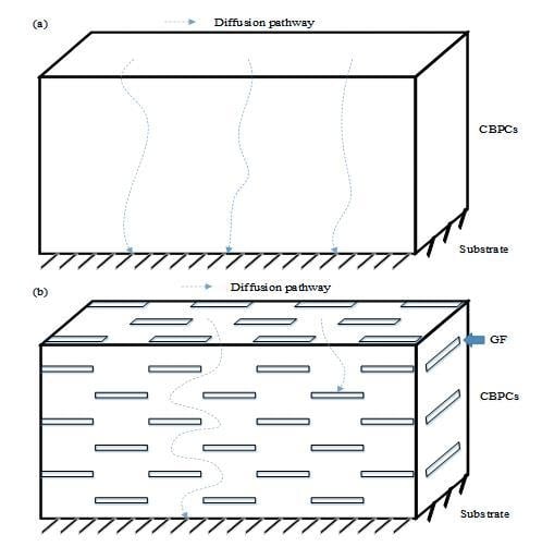
These results indicate that GF-reinforced chemically bonded phosphate ceramic coatings are potentially superior compared to the neat chemically bonded phosphate ceramics in terms of anti-corrosion property. To clarify the anticorrosion performance, a model of GF reinforced chemically bonded phosphate ceramic coating was established. As shown in Figure 10, for CBPC or GCBPC0, aggressive substances such as H2O, O2 and Cl− can be passed to the substrate through the diffusion route between the binding phase and the particle. However, the binding phase and the GF can hinder the aggressive substances permeation pathway and make the diffusion route more tortuous in GCBPCs, preventing H2O, O2 and Cl− from engaging the substrate effectively.
4. Conclusions
The glass flake-reinforced chemically bonded phosphate ceramic coatings were prepared on round steel. The crystalline phase, curing behavior, micromorphology and electrochemical performance of the coating were studied. The main conclusions can be obtained as follows:
- (1)
- With the addition of magnesia, a new bonding phase (Mg3(PO4)2) can be formed, which can help the GCBPCs obtain a more compact and denser structure. Meanwhile, The GF particles have a good adhesion with GCBPC and achieve a homogeneous and parallel dispersion on the surface and internal of the coatings.
- (2)
- The effect of the magnesia and the GF additives on curing behavior is obvious; the heat of reaction of the phosphate ceramic materials increases, which emphasizes the higher crosslinking density in the phosphate ceramic materials.
- (3)
- The phosphate ceramic coatings with the magnesia have a higher impedance value compared with the neat phosphate ceramic coating, while the highest impedance value is acquired with increase content of GF. It is found that GCBPC0 has a smaller particle size and a denser structure due to the new bonding phase compared with CBPC, and GF is distributed parallel on the surface and internal of the GCBPCs homogeneously. The corrosion mechanism is mainly contributed by the new bonding phase and GF, which can hinder the permeation pathway and make the permeation more circuitous.
Author Contributions
Conceptualization and Methodology, G.Y. and W.Y.; Validation, G.Y. and T.S.; Resources, T.S.; Data Curation, G.W.; Writing—Original Draft Preparation, G.Y.; Writing—Review & Editing, M.W. and X.L.
Funding
This study was financially supported by the National Key Research and Development Program of China (No. 2017YFB0310905), Yang Fan Innovative & Entrepreneurial Research Team Project (No. 201312C12), and the 111 Project (No. B18038).
Conflicts of Interest
The authors declare no conflict of interest.
References
- Yan, D.; Reis, S.; Tao, X.; Chen, G.; Brow, R.K.; Koenigstein, M. Effect of chemically reactive enamel coating on bonding strength at steel/mortar interface. Constr. Build. Mater. 2012, 28, 512–518. [Google Scholar] [CrossRef]
- Zhu, X.; Chen, Z.; Wang, H.; Chen, Y.; Xu, L. Probabilistic Generalization of a Comprehensive Model for the Deterioration Prediction of RC Structure under Extreme Corrosion Environments. Sustainability 2018, 10, 3051. [Google Scholar] [CrossRef]
- Selvaraj, R.; Selvaraj, M.; Iyer, S. Studies on the evaluation of the performance of organic coatings used for the prevention of corrosion of steel rebars in concrete structures. Prog. Org. Coat. 2009, 64, 454–459. [Google Scholar] [CrossRef]
- Kobayashi, K.; Takewaka, K. Experimental studies on epoxy coated reinforcing steel for corrosion protection. Int. J. Cem. Compos. Light. Concr. 1984, 6, 99–116. [Google Scholar] [CrossRef]
- Končan Volmajer, N.; Steinbücher, M.; Berce, P.; Venturini, P.; Gaberšček, M. Electrochemical Impedance Spectroscopy Study of Waterborne Epoxy Coating Film Formation. Coatings 2019, 9, 254. [Google Scholar] [CrossRef]
- Pour-Ali, S.; Dehghanian, C.; Kosari, A. Corrosion protection of the reinforcing steels in chloride-laden concrete environment through epoxy/polyaniline–camphorsulfonate nanocomposite coating. Corros. Sci. 2015, 90, 239–247. [Google Scholar] [CrossRef]
- Cheng, A.; Huang, R.; Wu, J.; Chen, C. Effect of rebar coating on corrosion resistance and bond strength of reinforced concrete. Constr. Build. Mater. 2005, 19, 404–412. [Google Scholar] [CrossRef]
- Tang, F.; Chen, G.; Brow, R.K.; Volz, J.S.; Koenigstein, M.L. Corrosion resistance and mechanism of steel rebar coated with three types of enamel. Corros. Sci. 2012, 59, 157–168. [Google Scholar] [CrossRef]
- Liu, Y.; Bian, D.; Zhao, Y.; Wang, Y. Influence of curing temperature on corrosion protection property of chemically bonded phosphate ceramic coatings with nano-titanium dioxide reinforcement. Ceram. Int. 2019, 45, 1595–1604. [Google Scholar] [CrossRef]
- Brown, M.C. Corrosion protection service life of epoxy coated reinforcing steel in virginia bridge decks. Diss. Abstr. Int. 2002, 63, 3825. [Google Scholar]
- Kayali, O.; Yeomans, S.R. Bond of ribbed galvanized reinforcing steel in concrete. Cem. Concr. Compos. 2000, 22, 459–467. [Google Scholar] [CrossRef]
- Arenas, M.A.; Casado, C.; Nobel-Pujol, V.; De Damborenea, J. Influence of the conversion coating on the corrosion of galvanized reinforcing steel. Cem. Concr. Compos. 2006, 28, 267–275. [Google Scholar] [CrossRef]
- Wagh, A.S.; Jeong, S.Y. Chemically Bonded Phosphate Ceramics: I, A Dissolution Model of Formation. J. Am. Ceram. Soc. 2003, 86, 1838–1844. [Google Scholar] [CrossRef]
- Formosa, J.; Chimenos, J.M.; Lacasta, A.M.; Niubó, M. Interaction between low-grade magnesium oxide and boric acid in chemically bonded phosphate ceramics formulation. Ceram. Int. 2012, 38, 2483–2493. [Google Scholar] [CrossRef]
- Wagh, A.S. Chemically Bonded Phosphate Ceramics, Twenty-First Century Materials with Diverse Applications, 2nd ed.; Elsevier: Naperville, IL, USA, 2016. [Google Scholar]
- Han, H.-J.; Kim, D.-P. Studies on Curing Chemistry of Aluminum-Chromium-Phosphates as Low Temperature Curable Binders. J. Sol-Gel Sci. Technol. 2003, 26, 223–228. [Google Scholar] [CrossRef]
- Hong, L.Y.; Han, H.J.; Ha, H.; Lee, J.Y.; Kim, D.P. Development of Cr-free aluminum phosphate binders and their composite applications. Compos. Sci. Technol. 2007, 67, 1195–1201. [Google Scholar] [CrossRef]
- Yang, X.; Huang, Y.; Zhang, J.; Cao, H. Preparation and properties of phosphate base heat-resisting composites. Chem. Adhes. 2005, 27, 67–70. [Google Scholar]
- Chen, D.; He, L.; Shang, S. Study on aluminum phosphate binder and related Al2O3–SiC ceramic coating. Mater. Sci. Eng. A 2003, 348, 29–35. [Google Scholar] [CrossRef]
- Moorlag, C.; Yang, Q.; Troczynski, T.; Bretherton, J.; Fyfe, C. Aluminum Phosphates Derived from Alumina and Alumina-Sol-Gel Systems. J. Am. Ceram. Soc. 2004, 87, 2064–2071. [Google Scholar] [CrossRef]
- Hawthorne, H.; Neville, A.; Troczynski, T.; Hu, X.; Thammachart, M.; Xie, Y.; Fu, J.; Yang, Q. Characterization of chemically bonded composite sol–gel based alumina coatings on steel substrates. Surf. Coat. Technol. 2004, 176, 243–252. [Google Scholar] [CrossRef]
- Vippola, M.; Ahmaniemi, S.; Keränen, J.; Vuoristo, P.; Lepistö, T.; Mäntylä, T.; Olsson, E. Aluminum phosphate sealed alumina coating: characterization of microstructure. Mater. Sci. Eng. A 2002, 323, 1–8. [Google Scholar] [CrossRef]
- Wagh, A.; Drozd, V. Inorganic Phosphate Corrosion Resistant Coatings. U.S. Patent US20130139930A1, 6 June 2013. [Google Scholar]
- Bian, D.; Zhao, Y. Preparation and corrosion mechanism of graphene-reinforced chemically bonded phosphate ceramics. J. Sol-Gel Sci. Technol. 2016, 80, 30–37. [Google Scholar] [CrossRef]
- Ding, Z.; Li, Y.Y.; Lu, C.; Liu, J. An Investigation of Fiber Reinforced Chemically Bonded Phosphate Ceramic Composites at Room Temperature. Materials 2018, 11, 858. [Google Scholar] [CrossRef] [PubMed]
- Lokuge, W.; Aravinthan, T. Effect of fly ash on the behaviour of polymer concrete with different types of resin. Mater. Des. 2013, 51, 175–181. [Google Scholar] [CrossRef]
- Momber, A.; Irmer, M.; Glück, N. Performance characteristics of protective coatings under low-temperature offshore conditions. Part 1: Experimental set-up and corrosion protection performance. Cold Reg. Sci. Technol. 2016, 127, 76–82. [Google Scholar] [CrossRef]
- Chi, S.; Park, J.; Shon, M. Study on cavitation erosion resistance and surface topologies of various coating materials used in shipbuilding industry. J. Ind. Eng. Chem. 2015, 26, 384–389. [Google Scholar] [CrossRef]
- Du, Y.; Sun, J.; Yang, H.; Yan, L. Recovery of gallium in the alumina production process from high-alumina coal fly ash. Rare Met. Mater. Eng. 2016, 45, 1893–1897. [Google Scholar]
- Barbhuiya, S.; Choudhury, M.I. Nanoscale Characterization of Glass Flake Filled Vinyl Ester Anti-Corrosion Coatings. Coatings 2017, 7, 116. [Google Scholar] [CrossRef]
- Manna, J.; Roy, B.; Sharma, P. Efficient hydrogen generation from sodium borohydride hydrolysis using silica sulfuric acid catalyst. J. Power Sources 2015, 275, 727–733. [Google Scholar] [CrossRef]
- Deng, S.; Wang, C.; Zhou, Y.; Huang, F.; Du, L. Preparation and Characterization of Fiber-Reinforced Aluminum Phosphate/Silica Composites with Interpenetrating Phase Structures. Int. J. Appl. Ceram. Technol. 2010, 8, 360–365. [Google Scholar] [CrossRef]
- Soudée, E.; Pera, J. Mechanism of setting reaction in magnesia-phosphate cements. Cem. Concr. Res. 2000, 30, 315–321. [Google Scholar] [CrossRef]
- Will, G. Powder Diffraction: The Rietveld Method and the Two Stage Method to Determine and Refine Crystal Structures from Powder Diffraction Data; Springer Science & Business Media: Bonn, Germany, 2006. [Google Scholar]
- Karasinski, E.; Da Luz, M.; Lepienski, C.M.; Coelho, L. Nanostructured coating based on epoxy/metal oxides: Kinetic curing and mechanical properties. Thermochim. Acta 2013, 569, 167–176. [Google Scholar] [CrossRef]
- Sari, M.G.; Saeb, M.R.; Shabanian, M.; Khaleghi, M.; Vahabi, H.; Vagner, C.; Zarrintaj, P.; Khalili, R.; Paran, S.M.R.; Ramezanzadeh, B.; et al. Epoxy/starch-modified nano-zinc oxide transparent nanocomposite coatings: A showcase of superior curing behavior. Prog. Org. Coat. 2018, 115, 143–150. [Google Scholar] [CrossRef]
- Romano, A.-P.; Olivier, M.-G.; Vandermiers, C.; Poelman, M. Influence of the curing temperature of a cataphoretic coating on the development of filiform corrosion of aluminium. Prog. Org. Coat. 2006, 57, 400–407. [Google Scholar] [CrossRef]
- Shao, F.; Yang, K.; Zhao, H.; Liu, C.; Wang, L.; Tao, S. Effects of inorganic sealant and brief heat treatments on corrosion behavior of plasma sprayed Cr2O3–Al2O3 composite ceramic coatings. Surf. Coat. Technol. 2015, 276, 8–15. [Google Scholar] [CrossRef]
- Golabadi, M.; Aliofkhazraei, M.; Toorani, M.; Rouhaghdam, A.S. Corrosion and cathodic disbondment resistance of epoxy coating on zinc phosphate conversion coating containing Ni2+ and Co2+. J. Ind. Eng. Chem. 2017, 47, 154–168. [Google Scholar] [CrossRef]
- Hosseini, M.; Ashassi-Sorkhabi, H.; Ghiasvand, H.A.Y. Corrosion Protection of Electro-Galvanized Steel by Green Conversion Coatings. J. Rare Earths 2007, 537–543. [Google Scholar] [CrossRef]
- Chang, C.H.; Huang, T.C.; Peng, C.W.; Yeh, T.C.; Lu, H.I.; Hung, W.I.; Weng, C.J.; Yang, T.I.; Yeh, J.M. Novel anticorrosion coatings prepared from polyaniline/graphene composites. Carbon 2012, 50, 5044–5051. [Google Scholar] [CrossRef]
Figure 1.
Curing process of phosphate ceramic coatings.

Figure 2.
Surface topography of GF.

Figure 3.
XRD patterns of GF.

Figure 4.
XRD patterns of phosphate ceramic coatings.

Figure 5.
DSC curves of phosphate ceramic materials.

Figure 6.
SEM micrographs of coating surfaces (after curing): (a) 1000× CBPC; (b) 5000× CBPC; (c) 1000× GCBPC0; (d) 5000× GCBPC0; (e) 500× GCBPC10; (f) 2000× GCBPC10. Notes: AP (alumina particles), BP (binding phases), MP (micro-porous).
Figure 6.
SEM micrographs of coating surfaces (after curing): (a) 1000× CBPC; (b) 5000× CBPC; (c) 1000× GCBPC0; (d) 5000× GCBPC0; (e) 500× GCBPC10; (f) 2000× GCBPC10. Notes: AP (alumina particles), BP (binding phases), MP (micro-porous).

Figure 7.
SEM images of the cross-section in GCBPCs: (a) 300×; (b) 5000×. Notes: AP (alumina particles), BP (binding phases), MP (micro-porous).
Figure 7.
SEM images of the cross-section in GCBPCs: (a) 300×; (b) 5000×. Notes: AP (alumina particles), BP (binding phases), MP (micro-porous).

Figure 8.
Potentiodynamic polarization curves of phosphate ceramic coatings.

Figure 9.
Nyquist and Bode plots of CBPCs.

Figure 10.
Schematic diagram of the anti-corrosion mechanism in (a) CBPCs and (b) GCBPCs.


Table 1.
Raw material of phosphate ceramic materials.
| Name | Chemical Formula | Manufacturer |
|---|---|---|
| Monoaluminium phosphate | Al(H2PO4)3 | - |
| Chromium trioxide | CrO3 | Sinopharm Chemical Reagent Co., Ltd., Shanghai, China |
| Alumina | Al2O3 | Aladdin Industrial Corporation Tech Co., Ltd., Shanghai, China |
| Magnesia | MgO | Sinopharm Chemical Reagent Co., Ltd., Shanghai, China |
| Glass flake (150 mesh) | SiO2 | Hebei Huawei Glass Flake Co., Ltd., Langfang, China |
Table 2.
Mixture proportion of phosphate ceramic coating pastes.
| Sample | MAP (g) | Powders (g) | H2O (g) | ||
|---|---|---|---|---|---|
| Al2O3 | MgO | GF | |||
| CBPC | 10.0 | 10.0 | - | - | 5.0 |
| GCBPC0 | 10.0 | 9.5 | 0.5 | 0 | 5.0 |
| GCBPC5 | 10.0 | 9.0 | 0.5 | 0.5 | 5.0 |
| GCBPC10 | 10.0 | 8.5 | 0.5 | 1.0 | 5.0 |
| GCBPC15 | 10.0 | 8.0 | 0.5 | 1.5 | 5.0 |
Table 3.
Thickness of phosphate ceramic coatings after curing.
| Coatings | |||||
|---|---|---|---|---|---|
| CBPC | GCBPC0 | GCBPC5 | GCBPC10 | GCBPC15 | |
| Thickness (μm) | 186 | 193 | 201 | 210 | 217 |
| Standard deviation | 0.3 | 0.2 | 0.2 | 0.3 | 0.2 |
Table 4.
Curing parameters from DSC curves.
| Sample | Tonset (°C) | Tp (°C) | Tendset (°C) | ΔH (J/g) |
|---|---|---|---|---|
| CBPC | 209.5 | 228.0 | 245.5 | −30.32 |
| GCBPC0 | 118.9 | 126.9 | 153.9 | −37.65 |
| GCBPC5 | 117.8 | 126.3 | 153.3 | −48.30 |
| GCBPC10 | 115.4 | 125.4 | 153.4 | −54.38 |
| GCBPC15 | 113.7 | 125.2 | 153.2 | −56.39 |
where Tonset, Tp, Tendset represents the temperature values of the onset, the peak and the endset, respectively, ΔH is the curing enthalpy.
Table 5.
Curing parameters based on the potentiodynamic polarization curves.
| Sample | Electrochemical Parameter | η (%) | ||
|---|---|---|---|---|
| Ecorr (V) | icorr (A/cm2) | Corrosion Rate (mm/a) | ||
| Bare Steel | −0.928 | 1.503 × 10⁻⁵ | 0.177 | - |
| CBPC | −0.303 | 8.312 × 10⁻⁶ | 0.098 | 44.69 |
| GCBPC0 | −0.272 | 7.396 × 10⁻⁶ | 0.087 | 50.79 |
| GCBPC5 | −0.222 | 3.134 × 10⁻⁶ | 0.037 | 79.15 |
| GCBPC10 | −0.157 | 1.082 × 10⁻⁶ | 0.013 | 92.80 |
| GCBPC15 | −0.094 | 4.522 × 10⁻⁷ | 0.005 | 96.99 |
where Ecorr, icorr represent the corrosion potential and corrosion current density, η is the effective inhibition, which is calculated from Equation (4).
Table 6.
EIS parameters from Nyquist and Bode plots.
| Sample | Rs (Ω·cm2) | Rc (Ω·cm2) | CPEc (Ω·cm2) | Nc | Rct (Ω·cm2) | CPEct (F/cm2) | Nct |
|---|---|---|---|---|---|---|---|
| Bare Steel | 9.46 | - | - | - | 1989 | 1.4327 × 10⁻⁴ | 0.75 |
| CBPC | 11.43 | 267 | 4.1701 × 10⁻⁵ | 0.69 | 12406 | 5.4811 × 10⁻⁵ | 0.67 |
| GCBPC0 | 11.27 | 371 | 2.0892 × 10⁻⁵ | 0.57 | 14187 | 9.5405 × 10⁻⁵ | 0.64 |
| GCBPC5 | 10.98 | 1128 | 3.1458 × 10⁻⁵ | 0.65 | 18370 | 3.6515 × 10⁻⁵ | 0.58 |
| GCBPC10 | 10.90 | 1509 | 2.9823 × 10⁻⁵ | 0.61 | 20619 | 4.785 × 10⁻⁵ | 0.53 |
| GCBPC15 | 10.88 | 1784 | 9.6835 × 10⁻⁶ | 0.54 | 20950 | 8.5690 × 10⁻⁵ | 0.57 |
where Rs, Rc, CPEc, Rct and CPEct represent the resistance of the solution, resistance of the CBPC coating, the nonideal capacity of the CBPC coating, the resistance of charge transfer and the nonideal capacity of the double layer, respectively.
Table 7.
Comparison of the EIS parameters from different coatings.
| Species | Rs (Ω·cm2) | Rc (Ω·cm2) | CPEc (Ω·cm2) | Nc | Rct (Ω·cm2) | CPEct (F/cm2) | Nct |
|---|---|---|---|---|---|---|---|
| CBPC | 11.43 | 267 | 4.1701 × 10⁻⁵ | 0.69 | 12406 | 5.4811 × 10⁻⁵ | 0.67 |
| GCBPC15 | 10.88 | 1784 | 9.6835 × 10⁻⁶ | 0.54 | 20950 | 8.5690 × 10⁻⁵ | 0.57 |
| Epoxy [39] | 100 | 28935 | 4.3417 × 10⁻⁶ | 0.75 | 44523 | 3.8667 × 10⁻⁶ | 0.22 |
| Galvanized [40] | 10 | 491.6 | 4.0417 × 10⁻⁵ | 0.80 | 2000 | 3.2378 × 10⁻⁵ | 0.66 |
| GCBPC0-ZnO [24] | - | 817.2 | 7.2100 × 10⁻⁵ | 0.64 | 911.7 | 3.8300 × 10⁻⁵ | 0.79 |
where Rs, Rc, CPEc, Rct and CPEct represent the resistance of the solution, the resistance of the coating, the nonideal capacity of the coating, the resistance of the charge transfer and the nonideal capacity of the double layer, respectively.
© 2019 by the authors. Licensee MDPI, Basel, Switzerland. This article is an open access article distributed under the terms and conditions of the Creative Commons Attribution (CC BY) license (http://creativecommons.org/licenses/by/4.0/).
Share and Cite
MDPI and ACS Style
Yan, G.; Wang, M.; Sun, T.; Li, X.; Wang, G.; Yin, W. Anti-Corrosion Property of Glass Flake Reinforced Chemically Bonded Phosphate Ceramic Coatings. Materials 2019, 12, 2082. https://doi.org/10.3390/ma12132082
AMA Style
Yan G, Wang M, Sun T, Li X, Wang G, Yin W. Anti-Corrosion Property of Glass Flake Reinforced Chemically Bonded Phosphate Ceramic Coatings. Materials. 2019; 12(13):2082. https://doi.org/10.3390/ma12132082
Chicago/Turabian StyleYan, Ge, Mingyang Wang, Tao Sun, Xinping Li, Guiming Wang, and Weisong Yin. 2019. "Anti-Corrosion Property of Glass Flake Reinforced Chemically Bonded Phosphate Ceramic Coatings" Materials 12, no. 13: 2082. https://doi.org/10.3390/ma12132082
Note that from the first issue of 2016, this journal uses article numbers instead of page numbers. See further details here.