Silicon and Iron as Resource-Efficient Anode Materials for Ambient-Temperature Metal-Air Batteries: A Review

 , , , and
Abstract
1. Introduction
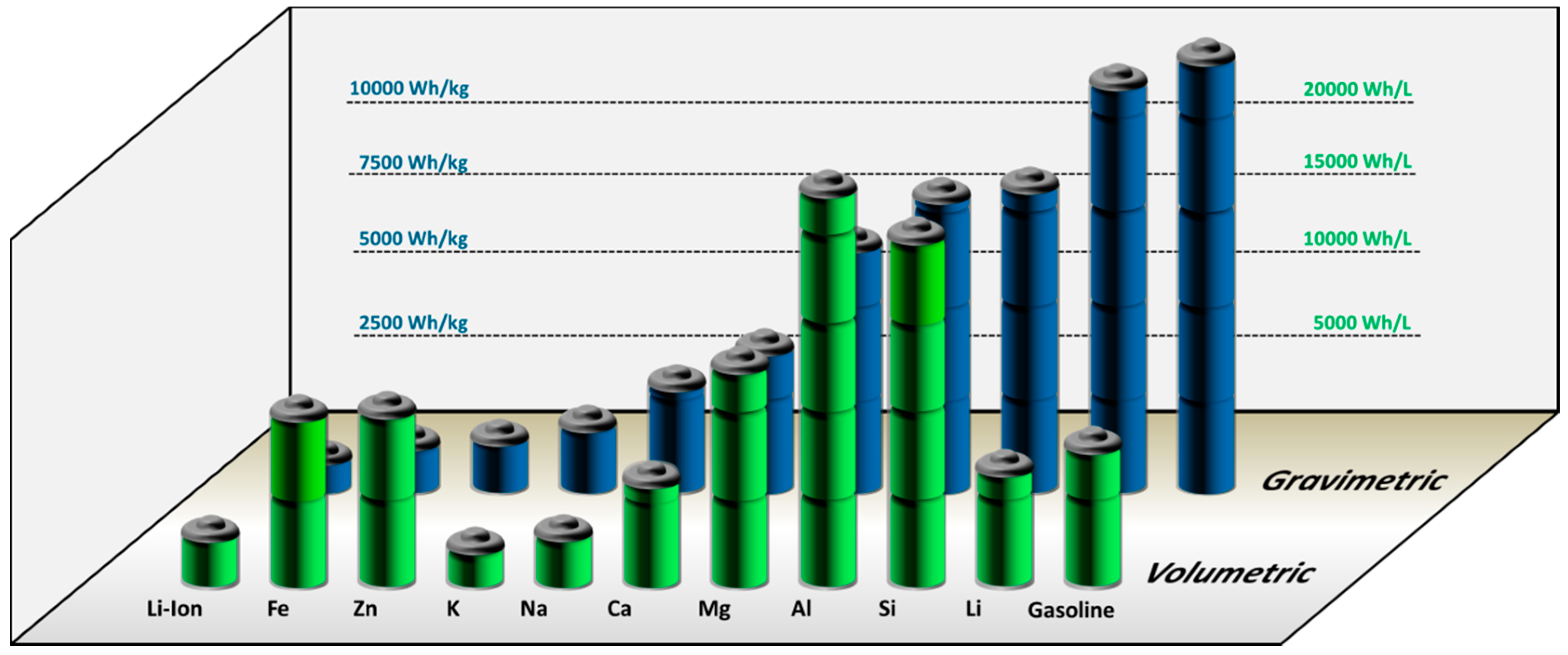
1.1. Motivation for Metal-Air Batteries
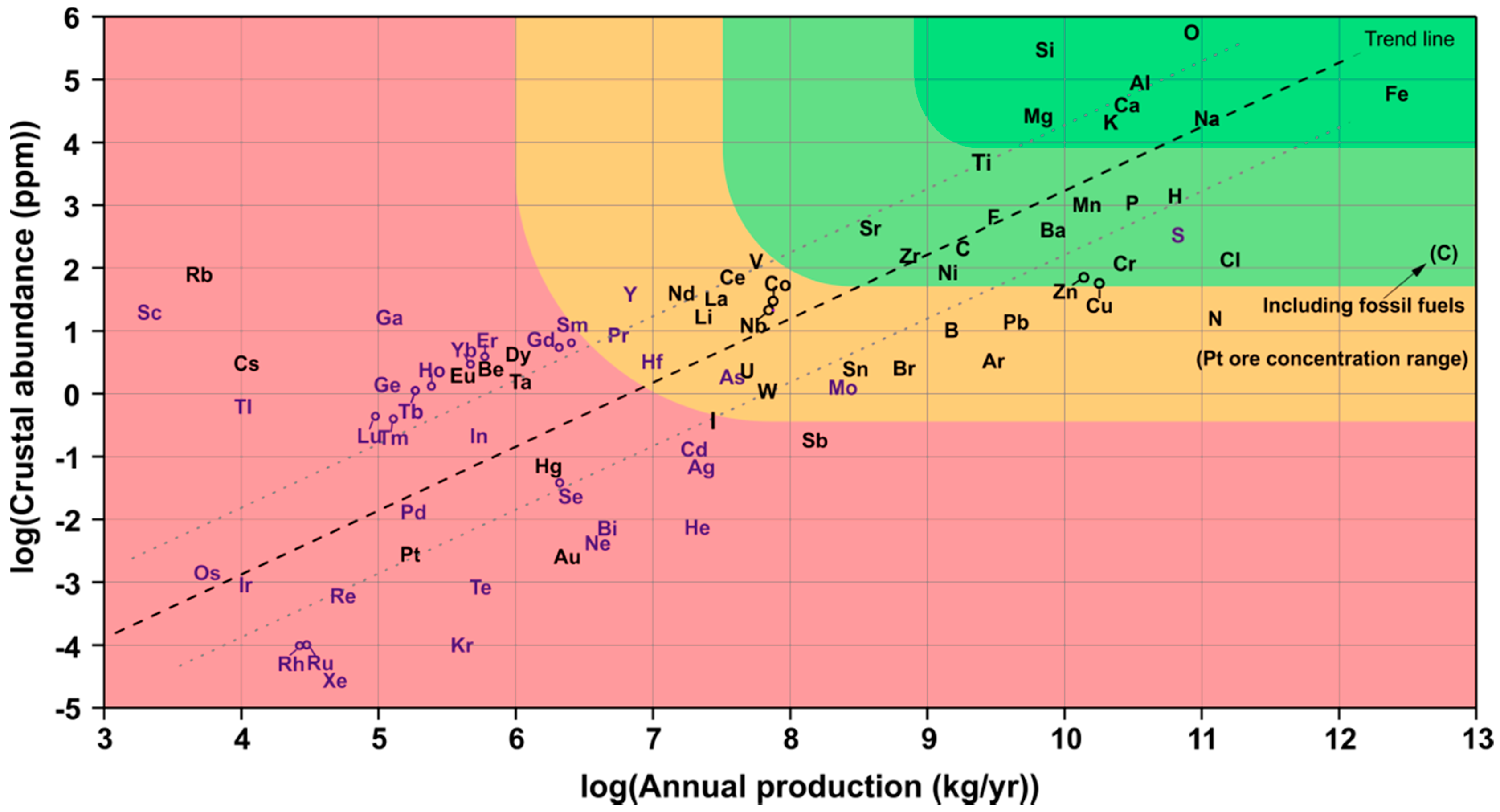
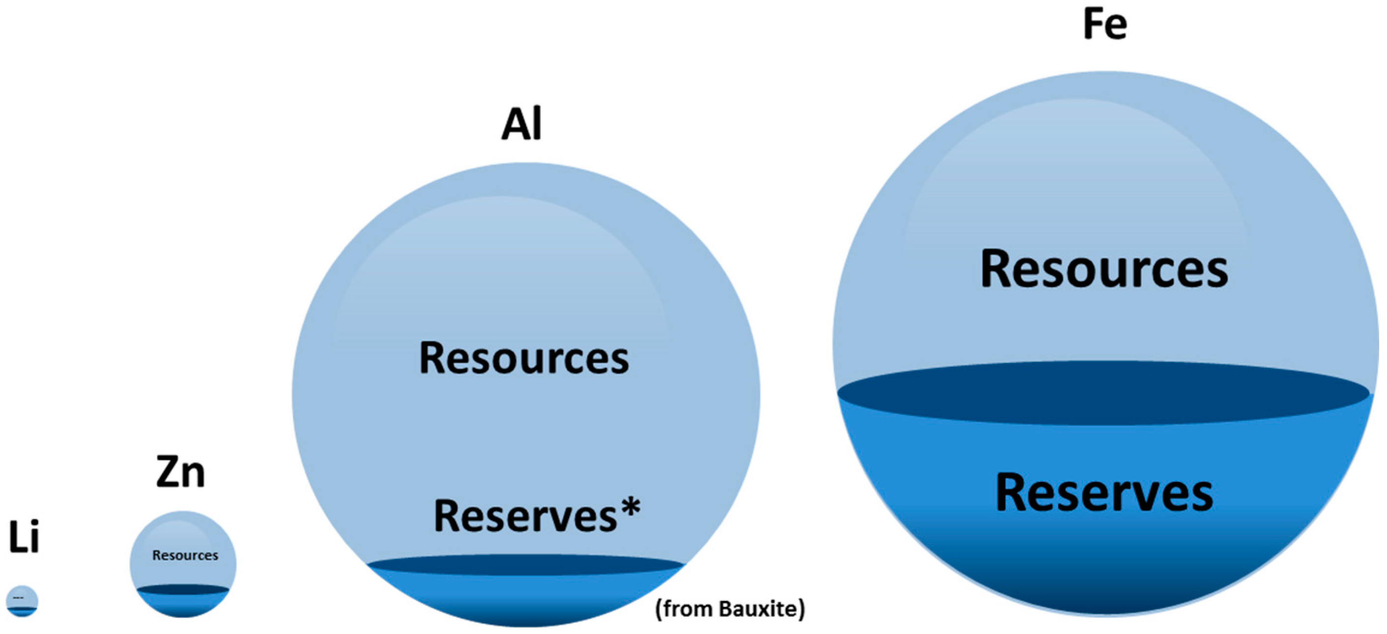
1.2. Resource-Efficiency
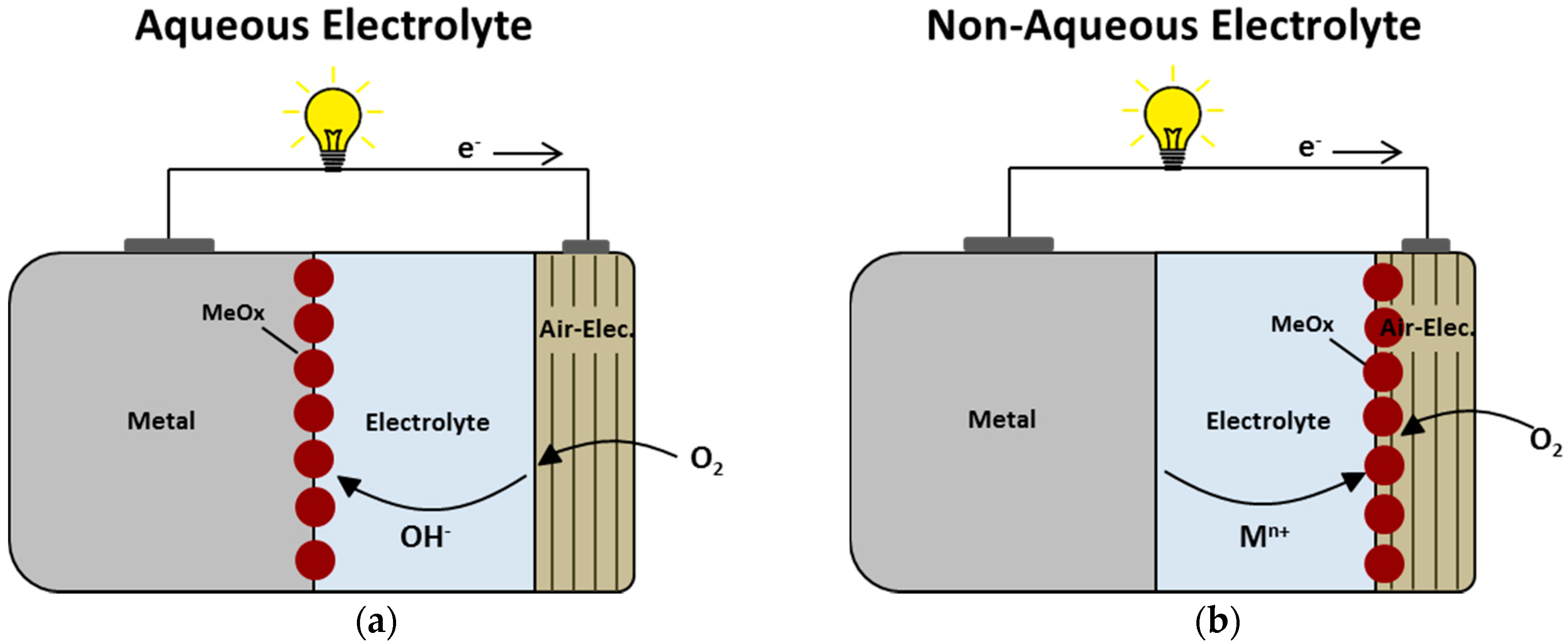
1.3. Challenges for Metal-Air Batteries
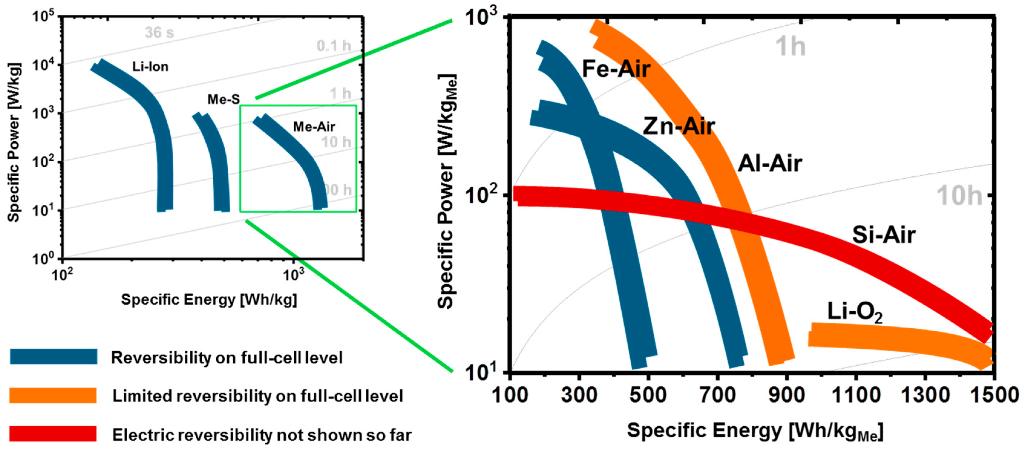
1.4. Electrochemical Performance of Metal-Air Batteries
2. Silicon-Air Batteries
2.1. Overview
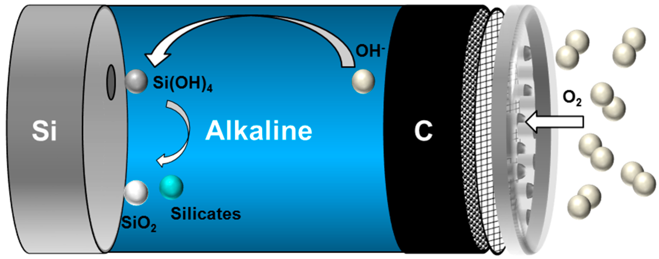
2.2. Aqueous Alkaline Si-air Cells
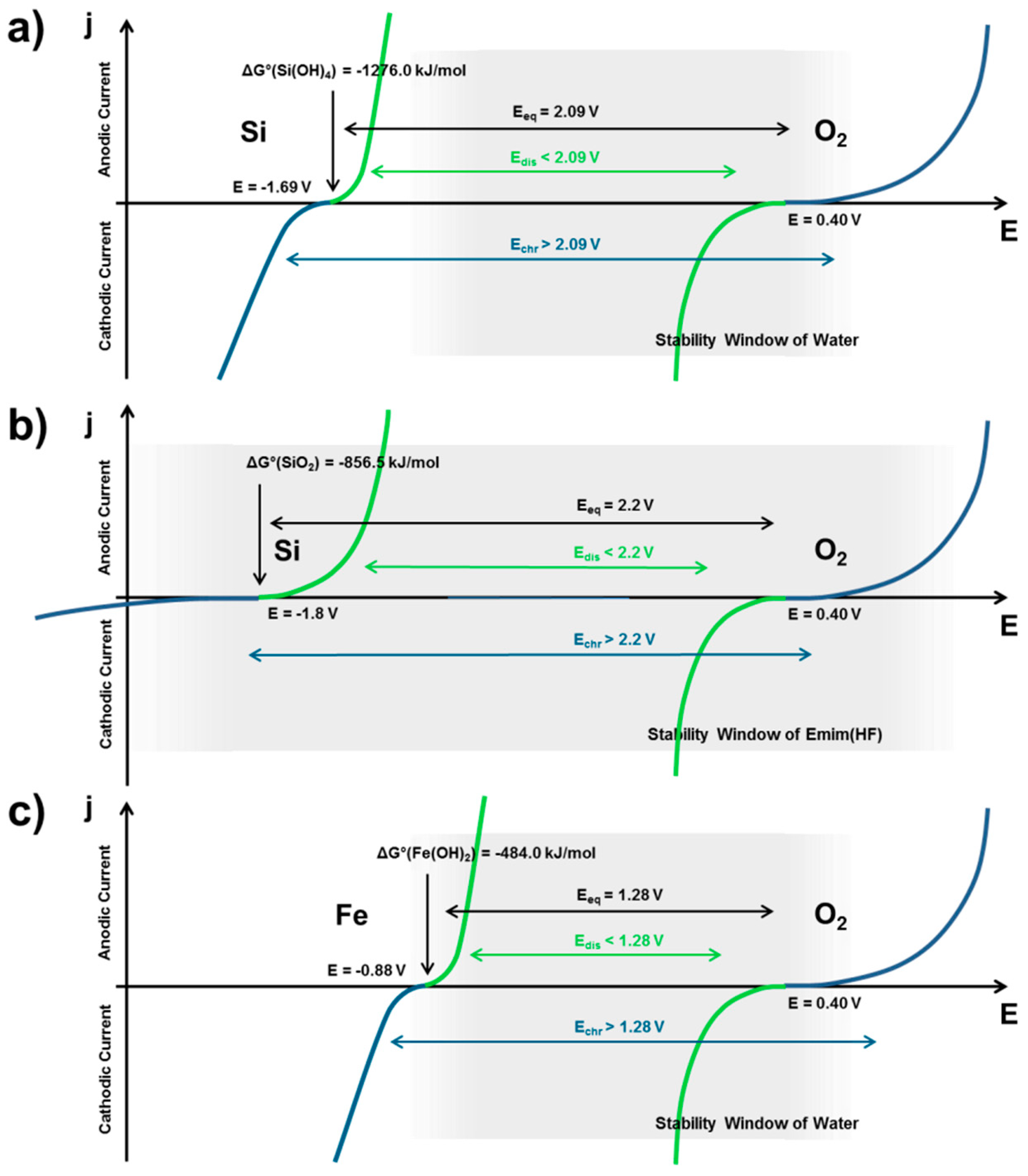
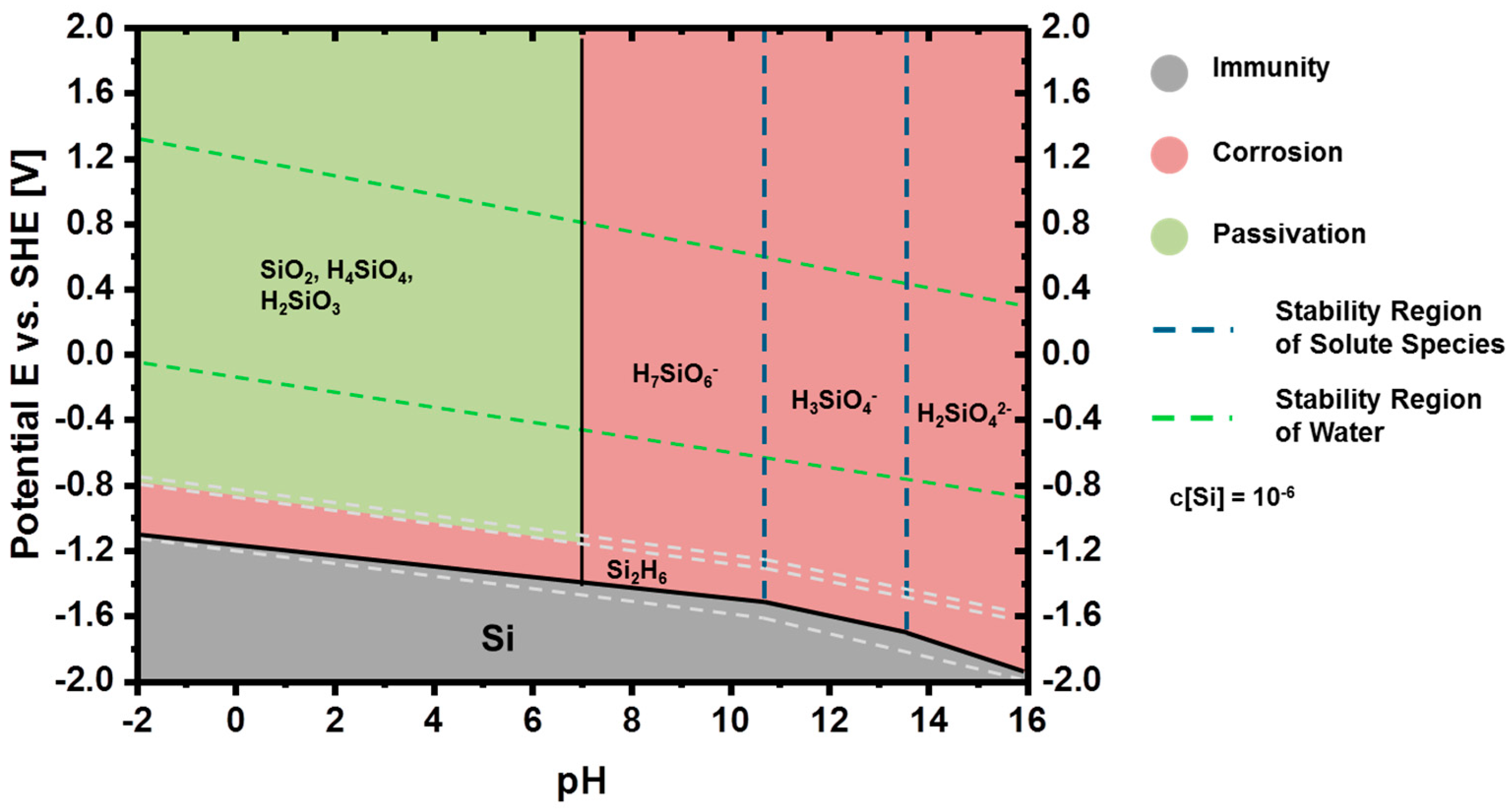
2.2.1. Thermodynamics of Si in Aqueous Electrolyte
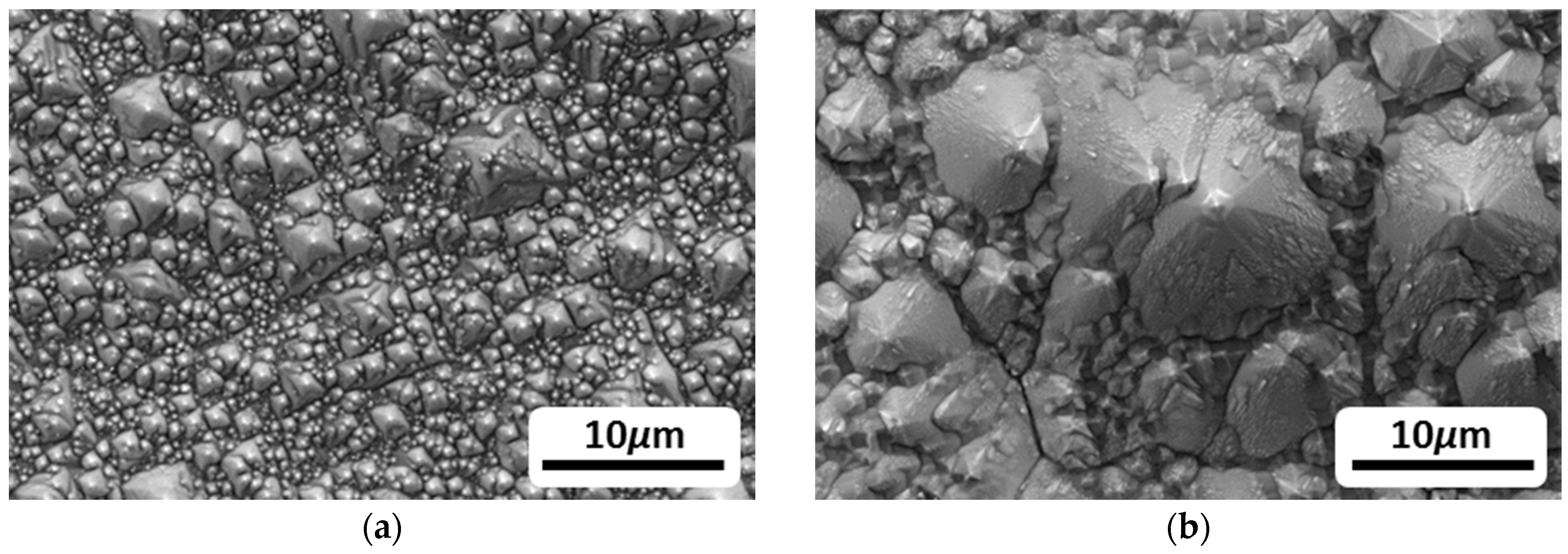
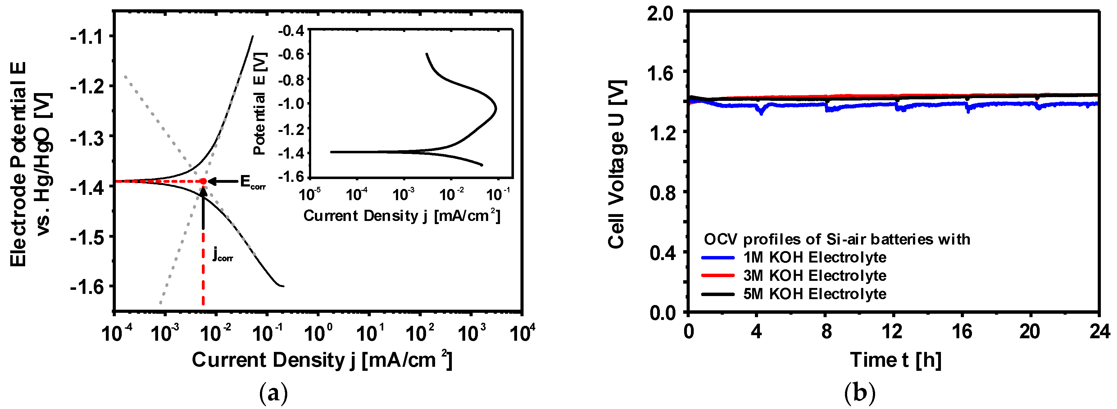
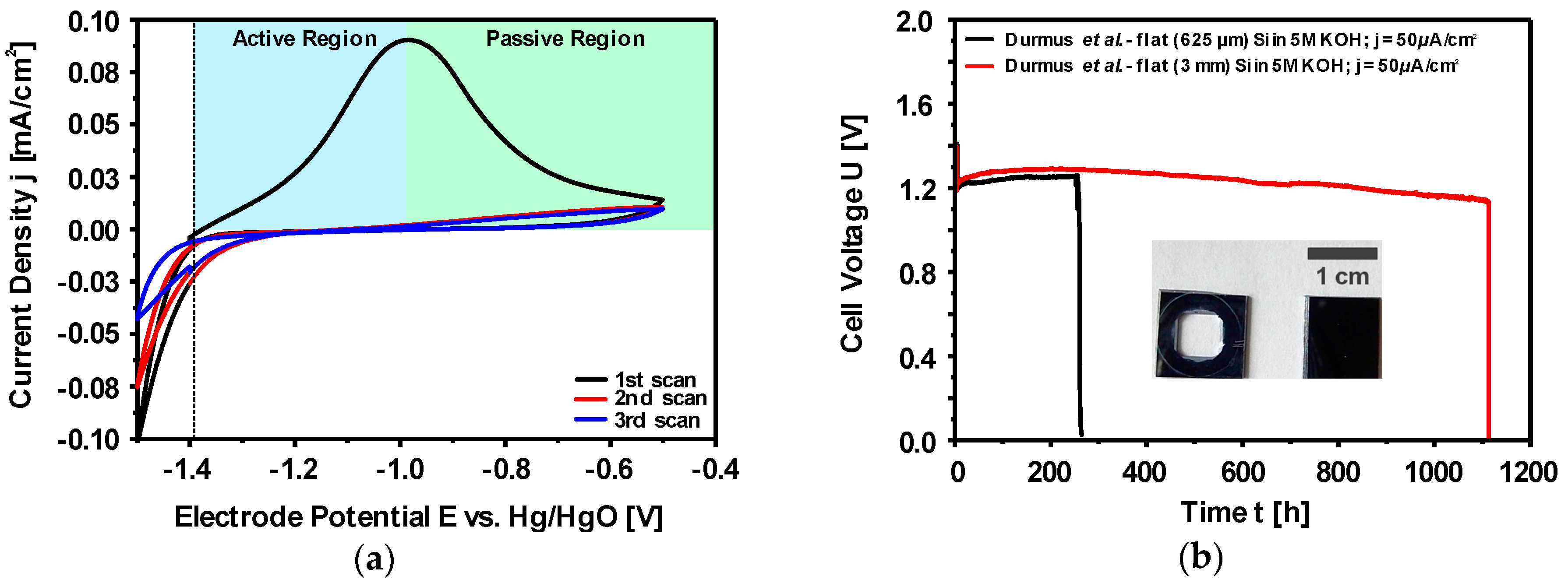
2.2.2. Corrosion Behavior of Si in Aqueous Alkaline Electrolyte
2.2.3. Discharge Behavior of Si in Aqueous Alkaline Electrolyte
2.3. Non-Aqueous Si-Air Cells
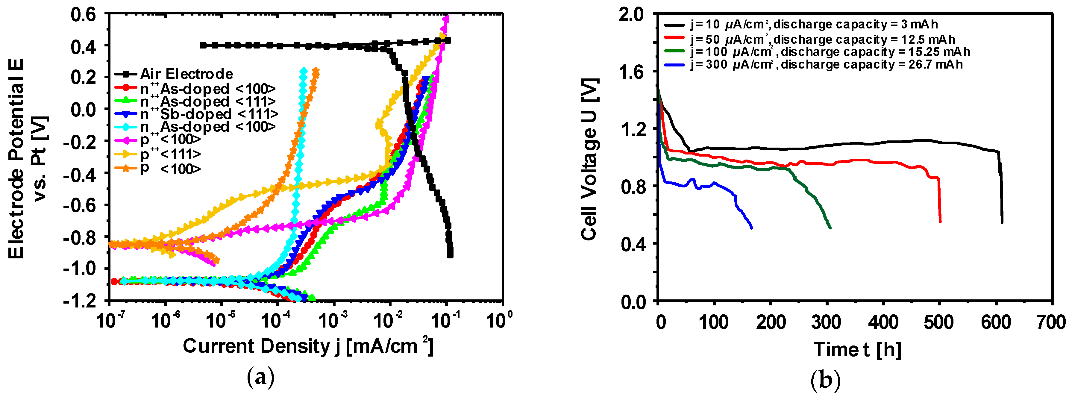
Electrochemical Characteristics of Silicon Electrodes
3. Iron-Air Batteries
3.1. Overview
3.2. Thermodynamics of Iron in Aqueous Electrolyte
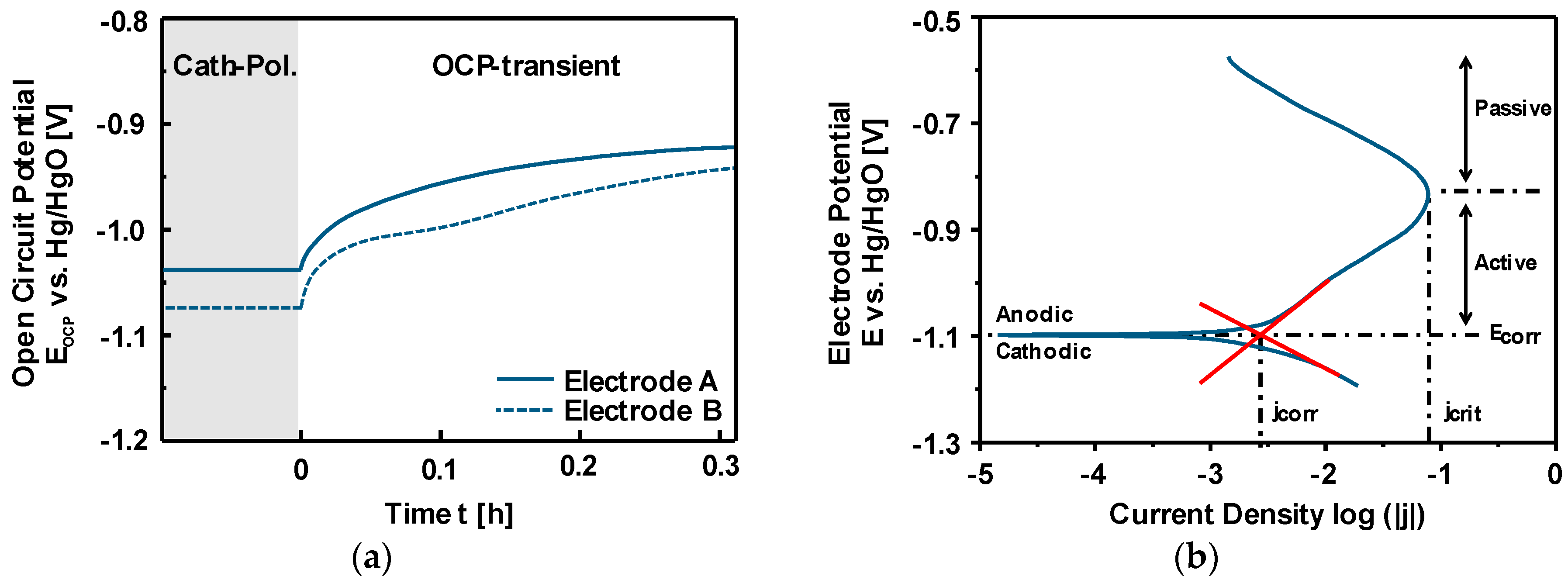
3.3. Discharge vs. Corrosion of Iron
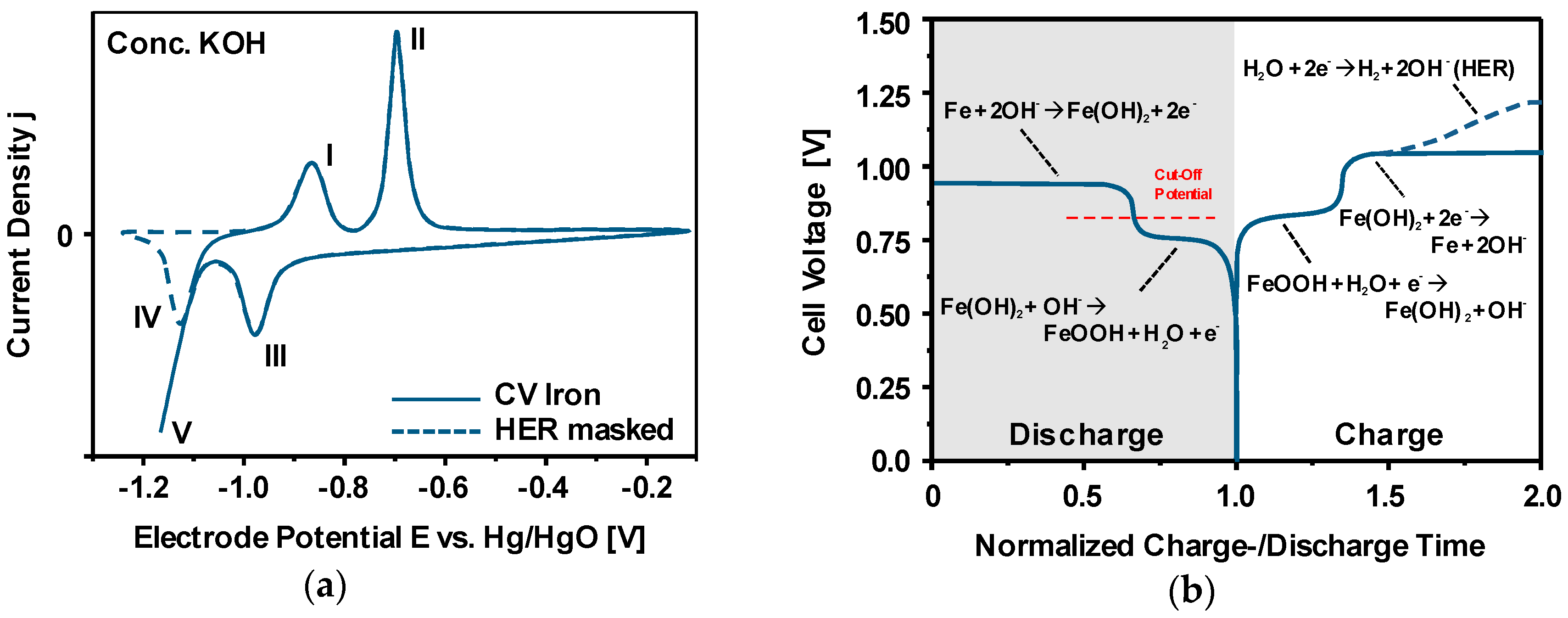
3.4. Charge-/Discharge Characteristics of Ferrous Electrodes
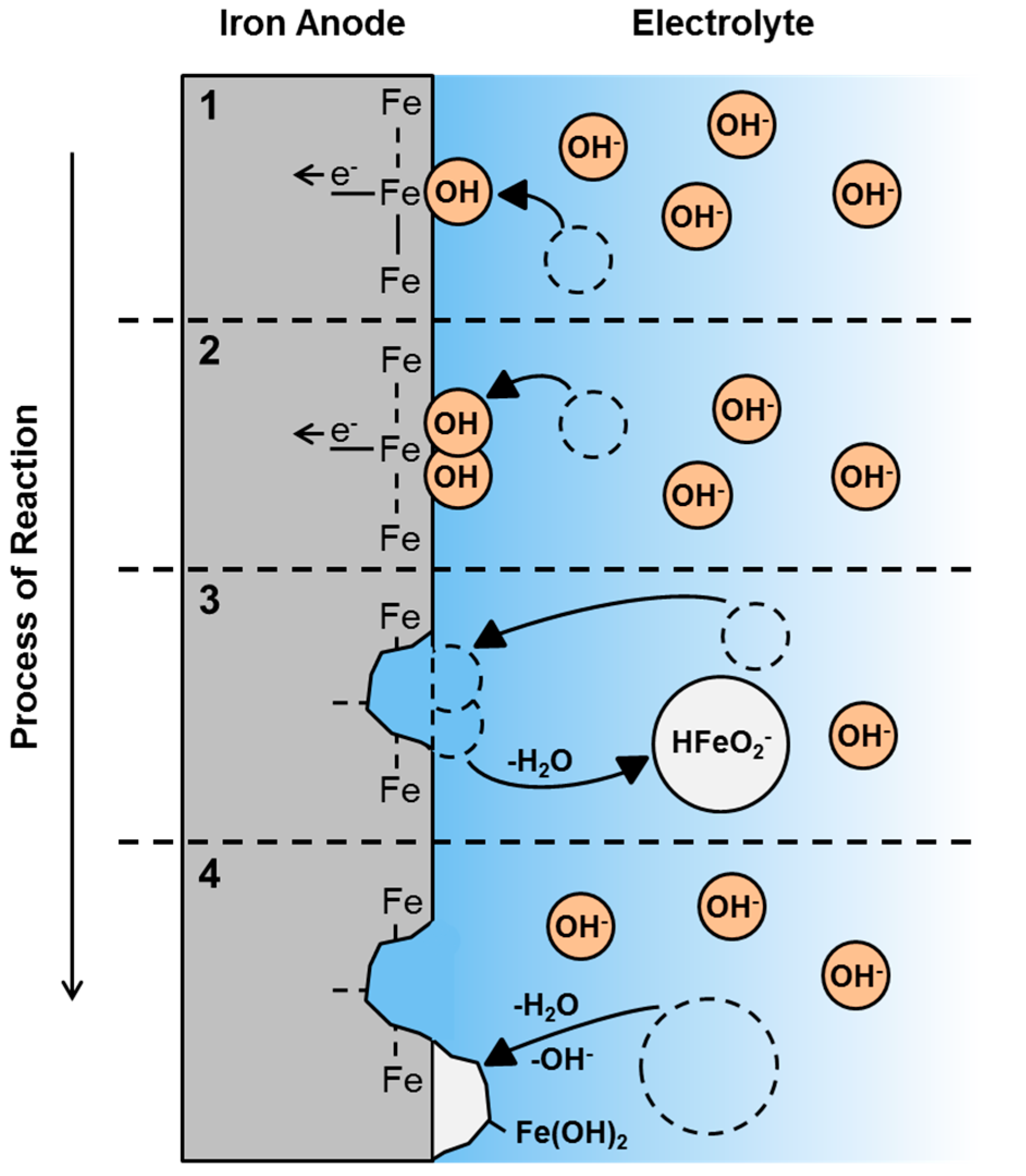
3.5. First Oxidation Mechanism of Iron in Alkaline Electrolyte
3.6. Electrode Concepts
3.6.1. Plane Electrode Sheets
3.6.2. Pressed-Plate Microparticles
3.6.3. Sintered Iron Electrodes
3.6.4. Nanoparticles
3.6.5. Nanoparticle-loaded Carbon Structures
3.6.6. Summarizing Remarks
3.7. Electrode- and Electrolyte Additives
3.8. Electrochemical Formation of Porous Iron Electrodes
4. Conclusions
Author Contributions
Funding
Conflicts of Interest
Appendix A


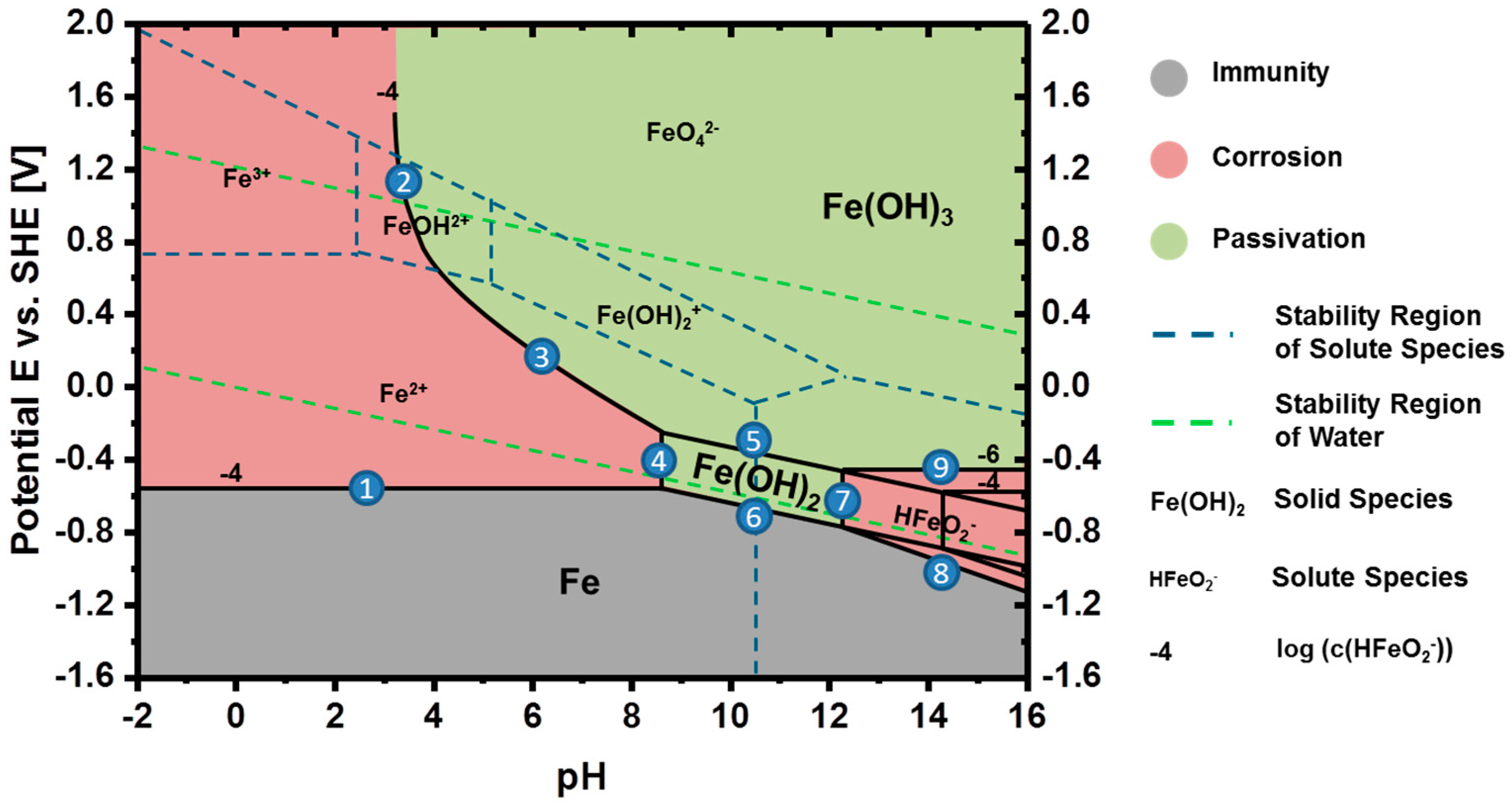
| # No. | Reaction |
|---|---|
| 1 | Fe ⇌ Fe2+ + 2e− |
| 2 | FeOH2+ + 2OH− ⇌ Fe(OH)3 |
| 3 | Fe2+ + 3OH− ⇌ Fe(OH)3 + 1e− |
| 4 | Fe2+ + 2OH− ⇌ Fe(OH)2 |
| 5 | Fe(OH)2 + OH− ⇌ Fe(OH)3 + 1e− |
| 6 | Fe + 2OH− ⇌ Fe(OH)2 + 2e− |
| 7 | Fe(OH)2 + OH− ⇌ HFeO2− + H2O |
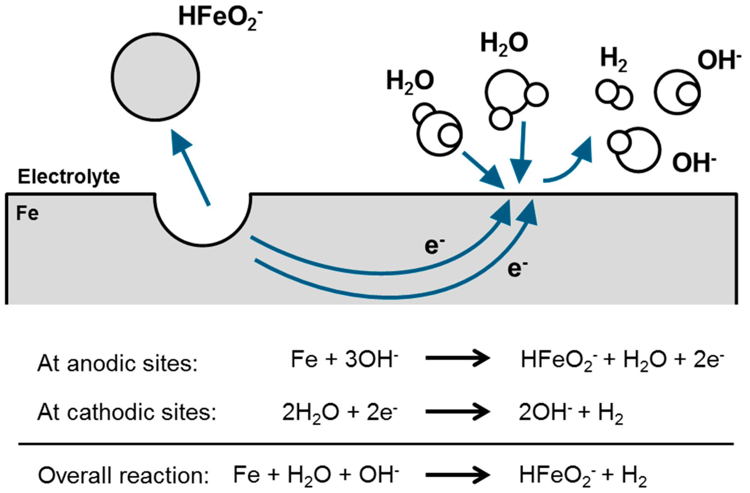
| 8 | Fe + 3OH− ⇌ HFeO2− + H2O + 2e− |
| 9 | HFeO2− + H2O ⇌ Fe(OH)3 + 1e− |
References
- United Nations. Paris Agreement; United Nations: New York, NY, USA, 2015. [Google Scholar]
- National Academy of Sciences. Climate Change: Evidence and Causes; National Academies Press: Washington DC, USA, 2014. [Google Scholar]
- World Health Organization. Strengthening Health Resilience to Climate Change; World Health Organization: Geneva, Switzerland, 2014. [Google Scholar]
- Ministère de la Transition Écologique et Solidaire. Impacts of Climate Change; Ministère de la Transition Écologique et Solidaire: Paris, France, 2015; Volume 213. [Google Scholar]
- World Energy Council. World Energy Resources; World Energy Council: London, UK, 2016. [Google Scholar]
- WWF. Annual Report; WWF: Washington, DC, USA, 2016. [Google Scholar]
- German Federal Ministry for Economic Affairs and Energy. Making a Success of the Energy Transition; German Federal Ministry for Economic Affairs and Energy: Berlin, Germany, 2015.
- EU Commission. Integration of Renewable Energy in Europe; EU Commission: Brussels, Belgium, 2014. [Google Scholar]
- Mathiesen, B.V.; Lund, H.; Connolly, D.; Wenzel, H.; Østergaard, P.A.; Möller, B.; Nielsen, S.; Ridjan, I.; Karnøe, P.; Sperling, K.; et al. Smart Energy Systems for coherent 100% renewable energy and transport solutions. Appl. Energy 2015, 145, 139–154. [Google Scholar] [CrossRef]
- Weitemeyer, S.; Kleinhans, D.; Vogt, T.; Agert, C. Integration of Renewable Energy Sources in future power systems: The role of storage. Renew. Energy 2015, 75, 14–20. [Google Scholar] [CrossRef]
- Foit, S.R.; Vinke, I.C.; De Haart, L.G.J.; Eichel, R.-A. Power-to-Syngas: An Enabling Technology for the Transition of the Energy System? Angew. Chem. Int. Ed. 2017, 56, 5402–5411. [Google Scholar] [CrossRef] [PubMed]
- Armand, M.; Tarascon, J.-M. Building better batteries. Nature 2008, 451, 652–657. [Google Scholar] [CrossRef] [PubMed]
- Dunn, B.; Kamath, H.; Tarascon, J.-M. Electrical Energy Storage for the Grid: A Battery of Choices. Science 2011, 334, 928–935. [Google Scholar] [CrossRef] [PubMed]
- Goodenough, J.B.; Kim, Y. Challenges for rechargeable batteries. J. Power Sour. 2011, 196, 6688–6694. [Google Scholar] [CrossRef]
- Van Noorden, R. The rechargeable revolution: A better battery. Nature 2014, 507, 26–28. [Google Scholar] [CrossRef]
- Nykvist, B.; Nilsson, M. Rapidly falling costs of battery packs for electric vehicles. Nat. Clim. Chang. 2015, 5, 329–332. [Google Scholar] [CrossRef]
- Choi, J.W.; Aurbach, D. Promise and reality of post-lithium-ion batteries with high energy densities. Nat. Rev. Mater. 2016, 1, 16013. [Google Scholar] [CrossRef]
- Winter, M.; Besenhard, J.O. Wiederaufladbare Batterien. Chem. Unserer Zeit 1999, 33, 320–332. [Google Scholar] [CrossRef]
- The Economist. Batteries Included? Available online: https://www.economist.com/science-and-technology/2013/02/02/batteries-included (accessed on 3 June 2019).
- Satell, G. Why Energy Storage May be the Most Important Technology in the World Right Now. Available online: https://www.forbes.com/sites/gregsatell/2016/04/01/why-energy-storage-may-be-the-most-important-technology-in-the-world-right-now/#1a3a709744e1 (accessed on 3 June 2019).
- Hurst, N. Charging Ahead: The Future of Batteries. Available online: https://www.smithsonianmag.com/innovation/charging-ahead-future-of-batteries-180962414/ (accessed on 3 June 2019).
- Linden, D.; Reddy, T.B. Handbook of Batteries, 3rd ed.; Linden, D., Reddy, T.B., Eds.; McGraw-Hill: New York, NY, USA, 2002; ISBN 0071359788. [Google Scholar]
- Mizushima, K.; Jones, P.C.; Wiseman, P.J.; Goodenough, J.B. LixCoO2 (0 < x <1): A new cathode material for batteries of high energy density. Mater. Res. Bull. 1980, 15, 783–789. [Google Scholar]
- BBC World. Tesla Mega-Battery in Australia Activated. Available online: https://www.bbc.com/news/world-australia-42190358 (accessed on 3 June 2019).
- Nitta, N.; Wu, F.; Lee, J.T.; Yushin, G. Li-ion battery materials: Present and future. Mater. Today 2015, 18, 252–264. [Google Scholar] [CrossRef]
- Ghadbeigi, L.; Harada, J.K.; Lettiere, B.R.; Sparks, T.D. Performance and resource considerations of Li-ion battery electrode materials. Energy Environ. Sci. 2015, 8, 1640–1650. [Google Scholar] [CrossRef]
- Goriparti, S.; Miele, E.; De Angelis, F.; Di Fabrizio, E.; Proietti Zaccaria, R.; Capiglia, C. Review on recent progress of nanostructured anode materials for Li-ion batteries. J. Power Sour. 2014, 257, 421–443. [Google Scholar] [CrossRef]
- Blomgren, G.E. The Development and Future of Lithium Ion Batteries. J. Electrochem. Soc. 2017, 164, A5019–A5025. [Google Scholar] [CrossRef]
- Larcher, D.; Tarascon, J.-M. Towards greener and more sustainable batteries for electrical energy storage. Nat. Chem. 2015, 7, 19–29. [Google Scholar] [CrossRef] [PubMed]
- U. S. Department of Energy. ARPA-E Funding Announcement, Grid-Scale Rampable Intermittent Dispatchable Storage (GRIDS); U.S. Department of Energy: Washington, DC, USA, 2010.
- Egbue, O.; Long, S. Barriers to widespread adoption of electric vehicles: An analysis of consumer attitudes and perceptions. Energy Policy 2012, 48, 717–729. [Google Scholar] [CrossRef]
- Shahan, Z. The 10 Electric Cars With Most Driving Range. Available online: https://cleantechnica.com/2017/12/24/10-electric-cars-driving-range/ (accessed on 3 June 2019).
- Luntz, A. Beyond Lithium Ion Batteries. J. Phys. Chem. Lett. 2015, 6, 300–301. [Google Scholar] [CrossRef] [PubMed]
- Amine, K.; Kanno, R.; Tzeng, Y. Rechargeable lithium batteries and beyond: Progress, challenges, and future directions. MRS Bull. 2014, 39, 395–401. [Google Scholar] [CrossRef]
- Peng, L.; Zhu, Y.; Chen, D.; Ruoff, R.S.; Yu, G. Two-Dimensional Materials for Beyond-Lithium-Ion Batteries. Adv. Energy Mater. 2016, 6, 1600025. [Google Scholar] [CrossRef]
- Lee, J.-S.; Tai Kim, S.; Cao, R.; Choi, N.-S.; Liu, M.; Lee, K.T.; Cho, J. Metal-Air Batteries with High Energy Density: Li-Air versus Zn-Air. Adv. Energy Mater. 2011, 1, 34–50. [Google Scholar] [CrossRef]
- Cheng, F.; Chen, J. Metal-air batteries: From oxygen reduction electrochemistry to cathode catalysts. Chem. Soc. Rev. 2012, 41, 2172–2192. [Google Scholar] [CrossRef] [PubMed]
- Rahman, M.A.; Wang, X.; Wen, C. High Energy Density Metal-Air Batteries: A Review. J. Electrochem. Soc. 2013, 160, A1759–A1771. [Google Scholar] [CrossRef]
- Kraytsberg, A.; Ein-Eli, Y. The impact of nano-scaled materials on advanced metal-air battery systems. Nano Energy 2013, 2, 468–480. [Google Scholar] [CrossRef]
- Christensen, J.; Albertus, P.; Sanchez-Carrera, R.S.; Lohmann, T.; Kozinsky, B.; Liedtke, R.; Ahmed, J.; Kojic, A. A Critical Review of Li/Air Batteries. J. Electrochem. Soc. 2012, 159, R1–R30. [Google Scholar] [CrossRef]
- Jung, K.-N.; Kim, J.; Yamauchi, Y.; Park, M.-S.; Lee, J.-W.; Kim, J.H. Rechargeable lithium–Air batteries: A perspective on the development of oxygen electrodes. J. Mater. Chem. A 2016, 4, 14050–14068. [Google Scholar] [CrossRef]
- Hammond, C.R. Properties of the Elements and Inorganic Compounds. In Handbook of Chemistry and Physics; Lide, D.R., Ed.; CRC Press: Boca Raton, FL, USA, 2003; ISBN 0849304849. pp. 1–96. [Google Scholar]
- Narayanan, S.R.; Prakash, G.K.S.; Manohar, A.; Yang, B.; Malkhandi, S.; Kindler, A. Materials challenges and technical approaches for realizing inexpensive and robust iron-air batteries for large-scale energy storage. Solid State Ionics 2012, 216, 105–109. [Google Scholar] [CrossRef]
- Li, Y.; Dai, H. Recent advances in zinc-air batteries. Chem. Soc. Rev. 2014, 43, 5257–5275. [Google Scholar] [CrossRef]
- Ren, X.; Wu, Y. A Low-Overpotential Potassium–Oxygen Battery Based on Potassium Superoxide. J. Am. Chem. Soc. 2013, 135, 2923–2926. [Google Scholar] [CrossRef]
- Das, S.K.; Lau, S.; Archer, L.A. Sodium–Oxygen batteries: A new class of metal-air batteries. J. Mater. Chem. A 2014, 2, 12623–12629. [Google Scholar] [CrossRef]
- Hartmann, P.; Bender, C.L.; Vračar, M.; Dürr, A.K.; Garsuch, A.; Janek, J.; Adelhelm, P. A rechargeable room-temperature sodium superoxide (NaO2) battery. Nat. Mater. 2013, 12, 228–232. [Google Scholar] [CrossRef] [PubMed]
- Reinsberg, P.; Bondue, C.J.; Baltruschat, H. Calcium–Oxygen Batteries as a Promising Alternative to Sodium–Oxygen Batteries. J. Phys. Chem. C 2016, 120, 22179–22185. [Google Scholar] [CrossRef]
- Ponrouch, A.; Frontera, C.; Bardé, F.; Palacín, M.R. Towards a calcium-based rechargeable battery. Nat. Mater. 2016, 15, 169–172. [Google Scholar] [CrossRef] [PubMed]
- Gelman, D.; Shvartsev, B.; Ein-Eli, Y. Challenges and Prospect of Non-aqueous Non-alkali (NANA) Metal–Air Batteries. Top. Curr. Chem. 2016, 374, 82. [Google Scholar] [CrossRef] [PubMed]
- Shiga, T.; Hase, Y.; Kato, Y.; Inoue, M.; Takechi, K. A rechargeable non-aqueous Mg–O2 battery. Chem. Commun. 2013, 49, 9152–9154. [Google Scholar] [CrossRef] [PubMed]
- Durmus, Y.E.; Aslanbas, Ö.; Kayser, S.; Tempel, H.; Hausen, F.; De Haart, L.G.J.; Granwehr, J.; Ein-Eli, Y.; Eichel, R.-A.; Kungl, H. Long run discharge, performance and efficiency of primary silicon-air cells with alkaline electrolyte. Electrochim. Acta 2017, 225, 215–224. [Google Scholar] [CrossRef]
- Cohn, G.; Ein-Eli, Y. Study and development of non-aqueous silicon-air battery. J. Power Sour. 2010, 195, 4963–4970. [Google Scholar] [CrossRef]
- Egan, D.R.; Ponce De León, C.; Wood, R.J.K.; Jones, R.L.; Stokes, K.R.; Walsh, F.C. Developments in electrode materials and electrolytes for aluminiume-air batteries. J. Power Sour. 2013, 236, 293–310. [Google Scholar] [CrossRef]
- Gelman, D.; Shvartsev, B.; Ein-Eli, Y. Aluminum-air battery based on an ionic liquid electrolyte. J. Mater. Chem. A 2014, 2, 20237–20242. [Google Scholar] [CrossRef]
- European Commission. List of Critical Raw Materials for the EU; European Commission: Brussels, Belgium, 2017. [Google Scholar]
- Sanderson, H. Electric Car Demand Sparks Lithium Supply Fears. Available online: https://www.ft.com/content/90d65356-4a9d-11e7-919a-1e14ce4af89b (accessed on 3 June 2019).
- Vesborg, P.C.K.; Jaramillo, T.F. Addressing the terawatt challenge: Scalability in the supply of chemical elements for renewable energy. RSC Adv. 2012, 2, 7933–7947. [Google Scholar] [CrossRef]
- U.S. Geological Survey. Mineral Commodity Summaries; U.S. Geological Survey: Reston, VA, USA, 2015; Volume 1.
- Royal Society of Chemistry Periodic Table-Zinc. Available online: http://www.rsc.org/periodic-table/element/30/zinc (accessed on 3 June 2019).
- Luk, J. High Zinc Prices Could Drive Substitution. Available online: https://www.metalbulletin.com/events/articles/3780007/article-high-zinc-prices-could-drive-substitution.html (accessed on 3 June 2019).
- Tran, H.P.; Schaubroeck, T.; Swart, P.; Six, L.; Coonen, P.; Dewulf, J. Recycling portable alkaline/ZnC batteries for a circular economy: An assessment of natural resource consumption from a life cycle and criticality perspective. Resour. Conserv. Recycl. 2018, 135, 265–278. [Google Scholar] [CrossRef]
- Clark, S.; Latz, A.; Horstmann, B. A Review of Model-Based Design Tools for Metal-Air Batteries. Batteries 2018, 4, 5. [Google Scholar] [CrossRef]
- Wang, F.; Borodin, O.; Gao, T.; Fan, X.; Sun, W.; Han, F.; Faraone, A.; Dura, J.A.; Xu, K.; Wang, C. Highly reversible zinc metal anode for aqueous batteries. Nat. Mater. 2018, 17, 543–549. [Google Scholar] [CrossRef] [PubMed]
- Metalary. Lithium Price. Available online: https://www.metalary.com/lithium-price/ (accessed on 3 June 2019).
- International Energy Agency. Global EV Outlook 2017; International Energy Agency: Paris, France, 2017; ISBN 9789264278882.
- Andrus, C.D. Principles of a Resource/Reserve Classification For Minerals; U.S. Geological Survey: Reston, VA, USA, 1980.
- Statista. Number of Cars Sold Worldwide from 1990 to 2018; Statista: Hamburg, Germany, 2018. [Google Scholar]
- Gaines, L. The future of automotive lithium-ion battery recycling: Charting a sustainable course. Sustain. Mater. Technol. 2014, 1, 2–7. [Google Scholar] [CrossRef]
- Hamlen, R.P.; Atwater, T.B. Chapter 38 Metal/Air Batteries. In Handbook of Batteries; Linden, D., Reddy, T.B., Eds.; McGraw-Hill: New York, NY, USA, 2002; pp. 1209–1261. [Google Scholar]
- Arai, H.; Hayashi, M. Secondary Batteries—Metal-Air Systems. In Encyclopedia of Electrochemical Power Sources; Garche, J., Dyer, C.K., Moseley, P.T., Ogumi, Z., Rand, D.A.J., Scrosati, B., Eds.; Elsevier B.V.: Amsterdam, The Netherlands, 2009; pp. 347–354. [Google Scholar]
- Wang, Z.-L.; Xu, D.; Xu, J.-J.; Zhang, X.-B. Oxygen electrocatalysts in metal-air batteries: From aqueous to nonaqueous electrolytes. Chem. Soc. Rev. 2014, 43, 7746–7786. [Google Scholar] [CrossRef] [PubMed]
- Lee, D.U.; Xu, P.; Cano, Z.P.; Kashkooli, A.G.; Park, M.G.; Chen, Z. Recent progress and perspectives on bi-functional oxygen electrocatalysts for advanced rechargeable metal-air batteries. J. Mater. Chem. A 2016, 4, 7107–7134. [Google Scholar] [CrossRef]
- Jörissen, L. Bifunctional oxygen/air electrodes. J. Power Sour. 2006, 155, 23–32. [Google Scholar] [CrossRef]
- Xia, B.Y.; Yan, Y.; Li, N.; Wu, H.B.; Lou, X.W.D.; Wang, X. A metal-organic framework-derived bifunctional oxygen electrocatalyst. Nat. Energy 2016, 1, 1–8. [Google Scholar] [CrossRef]
- Aijaz, A.; Masa, J.; Rösler, C.; Xia, W.; Weide, P.; Botz, A.J.R.; Fischer, R.A.; Schuhmann, W.; Muhler, M. Co@Co3O4 Encapsulated in Carbon Nanotube-Grafted Nitrogen-Doped Carbon Polyhedra as an Advanced Bifunctional Oxygen Electrode. Angew. Chem. Int. Ed. 2016, 55, 4087–4091. [Google Scholar] [CrossRef] [PubMed]
- Zhang, J.; Zhao, Z.; Xia, Z.; Dai, L. A metal-free bifunctional electrocatalyst for oxygen reduction and oxygen evolution reactions. Nat. Nanotechnol. 2015, 10, 444–452. [Google Scholar] [CrossRef]
- Wang, K.; Pei, P.; Ma, Z.; Chen, H.; Xu, H.; Chen, D.; Wang, X. Dendrite growth in the recharging process of zinc-air batteries. J. Mater. Chem. A 2015, 3, 22648–22655. [Google Scholar] [CrossRef]
- Hardwick, L.; De Leόn, C.P. Rechargeable Metal-Air Batteries. Johns. Matthey Technol. Rev. 2018, 62, 134–149. [Google Scholar] [CrossRef]
- McCloskey, B.D.; Scheffler, R.; Speidel, A.; Bethune, D.S.; Shelby, R.M.; Luntz, A.C. On the Efficacy of Electrocatalysis in Nonaqueous Li–O2 Batteries. J. Am. Chem. Soc. 2011, 133, 18038–18041. [Google Scholar] [CrossRef] [PubMed]
- Girishkumar, G.; McCloskey, B.; Luntz, A.C.; Swanson, S.; Wilcke, W. Lithium-air battery: Promise and challenges. J. Phys. Chem. Lett. 2010, 1, 2193–2203. [Google Scholar] [CrossRef]
- Jung, H.-G.; Hassoun, J.; Park, J.-B.; Sun, Y.-K.; Scrosati, B. An improved high-performance lithium-air battery. Nat. Chem. 2012, 4, 579–585. [Google Scholar] [CrossRef] [PubMed]
- Freunberger, S.A.; Chen, Y.; Drewett, N.E.; Hardwick, L.J.; Bardé, F.; Bruce, P.G. The Lithium-Oxygen Battery with Ether-Based Electrolytes. Angew. Chem. Int. Ed. 2011, 50, 8609–8613. [Google Scholar] [CrossRef] [PubMed]
- Wandt, J.; Jakes, P.; Granwehr, J.; Gasteiger, H.A.; Eichel, R.-A. Singlet Oxygen Formation during the Charging Process of an Aprotic Lithium-Oxygen Battery. Angew. Chem. Int. Ed. 2016, 55, 6892–6895. [Google Scholar] [CrossRef] [PubMed]
- Elia, G.A.; Marquardt, K.; Hoeppner, K.; Fantini, S.; Lin, R.; Knipping, E.; Peters, W.; Drillet, J.-F.; Passerini, S.; Hahn, R. An Overview and Future Perspectives of Aluminum Batteries. Adv. Mater. 2016, 28, 7564–7579. [Google Scholar] [CrossRef] [PubMed]
- Durmus, Y.E.; Jakobi, S.; Beuse, T.; Aslanbas, Ö.; Tempel, H.; Hausen, F.; De Haart, L.G.J.; Ein-Eli, Y.; Eichel, R.-A.; Kungl, H. Influence of Dopant Type and Orientation of Silicon Anodes on Performance, Efficiency and Corrosion of Silicon–Air Cells with EMIm(HF) 2.3 F Electrolyte. J. Electrochem. Soc. 2017, 164, A2310–A2320. [Google Scholar] [CrossRef]
- Kraytsberg, A.; Ein-Eli, Y. Review on Li-air batteries—Opportunities, limitations and perspective. J. Power Sour. 2011, 196, 886–893. [Google Scholar] [CrossRef]
- Luntz, A.C.; McCloskey, B.D. Nonaqueous Li–Air Batteries: A Status Report. Chem. Rev. 2014, 114, 11721–11750. [Google Scholar] [CrossRef] [PubMed]
- Sharon, D.; Hirshberg, D.; Afri, M.; Frimer, A.A.; Noked, M.; Aurbach, D. Aprotic metal-oxygen batteries: Recent findings and insights. J. Solid State Electrochem. 2017, 21, 1861–1878. [Google Scholar] [CrossRef]
- Eftekhari, A.; Jian, Z.; Ji, X. Potassium Secondary Batteries. ACS Appl. Mater. Interfaces 2017, 9, 4404–4419. [Google Scholar] [CrossRef] [PubMed]
- Medenbach, L.; Adelhelm, P. Cell Concepts of Metal–Sulfur Batteries (Metal = Li, Na, K, Mg): Strategies for Using Sulfur in Energy Storage Applications. Top. Curr. Chem. 2017, 375, 81. [Google Scholar] [CrossRef] [PubMed]
- Liang, X.; Hart, C.; Pang, Q.; Garsuch, A.; Weiss, T.; Nazar, L.F. A highly efficient polysulfide mediator for lithium-sulfur batteries. Nat. Commun. 2015, 6, 5682. [Google Scholar] [CrossRef] [PubMed]
- Shangguan, E.; Li, F.; Li, J.; Chang, Z.; Li, Q.; Yuan, X.-Z.; Wang, H. FeS/C composite as high-performance anode material for alkaline nickel-iron rechargeable batteries. J. Power Sour. 2015, 291, 29–39. [Google Scholar] [CrossRef]
- Li, Y.; Gong, M.; Liang, Y.; Feng, J.; Kim, J.-E.; Wang, H.; Hong, G.; Zhang, B.; Dai, H. Advanced zinc-air batteries based on high-performance hybrid electrocatalysts. Nat. Commun. 2013, 4, 1805. [Google Scholar] [CrossRef]
- Wang, H.; Liang, Y.; Gong, M.; Li, Y.; Chang, W.; Mefford, T.; Zhou, J.; Wang, J.; Regier, T.; Wei, F.; et al. An ultrafast nickel-iron battery from strongly coupled inorganic nanoparticle/nanocarbon hybrid materials. Nat. Commun. 2012, 3, 917. [Google Scholar] [CrossRef]
- Figueredo-Rodríguez, H.A.; McKerracher, R.D.; Insausti, M.; Luis, A.G.; De Leόn, C.P.; Alegre, C.; Baglio, V.; Aricò, A.S.; Walsh, F.C. A Rechargeable, Aqueous Iron Air Battery with Nanostructured Electrodes Capable of High Energy Density Operation. J. Electrochem. Soc. 2017, 164, A1148–A1157. [Google Scholar] [CrossRef]
- Chen, Z.; Yu, A.; Higgins, D.; Li, H.; Wang, H.; Chen, Z. Highly Active and Durable Core—Corona Structured Bifunctional Catalyst for Rechargeable Metal—Air Battery Application. Nano Lett. 2012, 12, 1946–1952. [Google Scholar] [CrossRef]
- Riaz, A.; Jung, K.-N.; Chang, W.; Shin, K.-H.; Lee, J.-W. Carbon-, Binder-, and Precious Metal-Free Cathodes for Non-Aqueous Lithium–Oxygen Batteries: Nanoflake-Decorated Nanoneedle Oxide Arrays. ACS Appl. Mater. Interfaces 2014, 6, 17815–17822. [Google Scholar] [CrossRef] [PubMed]
- Mori, R. A novel aluminium–Air rechargeable battery with Al2O3 as the buffer to suppress byproduct accumulation directly onto an aluminium anode and air cathode. RSC Adv. 2014, 4, 30346–30351. [Google Scholar] [CrossRef]
- Yang, C.; Manohar, A.K.; Narayanan, S.R. A High-Performance Sintered Iron Electrode for Rechargeable Alkaline Batteries to Enable Large-Scale Energy Storage. J. Electrochem. Soc. 2017, 164, A418–A429. [Google Scholar] [CrossRef]
- Xiao, N.; Ren, X.; He, M.; McCulloch, W.D.; Wu, Y. Probing Mechanisms for Inverse Correlation between Rate Performance and Capacity in K–O2 Batteries. ACS Appl. Mater. Interfaces 2017, 9, 4301–4308. [Google Scholar] [CrossRef] [PubMed]
- Yadegari, H.; Banis, M.N.; Xiao, B.; Sun, Q.; Li, X.; Lushington, A.; Wang, B.; Li, R.; Sham, T.-K.; Cui, X.; et al. Three-Dimensional Nanostructured Air Electrode for Sodium–Oxygen Batteries: A Mechanism Study toward the Cyclability of the Cell. Chem. Mater. 2015, 27, 3040–3047. [Google Scholar] [CrossRef]
- Zhang, T.; Tao, Z.; Chen, J. Magnesium-air batteries: From principle to application. Mater. Horiz. 2014, 1, 196–206. [Google Scholar] [CrossRef]
- Vardar, G.; Nelson, E.G.; Smith, J.G.; Naruse, J.; Hiramatsu, H.; Bartlett, B.M.; Sleightholme, A.E.S.; Siegel, D.J.; Monroe, C.W. Identifying the Discharge Product and Reaction Pathway for a Secondary Mg/O2 Battery. Chem. Mater. 2015, 27, 7564–7568. [Google Scholar] [CrossRef]
- Jian, Z.; Liu, P.; Li, F.; He, P.; Guo, X.; Chen, M.; Zhou, H. Core-Shell-Structured CNT@RuO2 Composite as a High-Performance Cathode Catalyst for Rechargeable Li-O2 Batteries. Angew. Chem. 2014, 126, 452–456. [Google Scholar] [CrossRef]
- El Abedin, S.Z.; Borissenko, N.; Endres, F. Electrodeposition of nanoscale silicon in a room temperature ionic liquid. Electrochem. Commun. 2004, 6, 510–514. [Google Scholar] [CrossRef]
- Zahlbach, J.; Cui, T.; Pulletikurthi, G.; Atkin, R.; Borisenko, N.; Carstens, T.; Endres, F.; Lahiri, A. The Au(111)/IL interfacial nanostructure in the presence of precursors and its influence on the electrodeposition process. Faraday Discuss. 2017, 206, 459–473. [Google Scholar]
- Lahiri, A.; Pulletikurthi, G.; Behrens, N.; Cui, T.; Endres, F. In Situ Atomic Force Microscopy and Electrochemical Quartz Crystal Microbalance Studies on the Electrodeposition and Oxidation of Silicon. J. Phys. Chem. C 2018, 122, 14499–14510. [Google Scholar] [CrossRef]
- Manohar, A.K.; Yang, C.; Narayanan, S.R. The Role of Sulfide Additives in Achieving Long Cycle Life Rechargeable Iron Electrodes in Alkaline Batteries. J. Electrochem. Soc. 2015, 162, A1864–A1872. [Google Scholar] [CrossRef]
- Durmus, Y.E.; Guerrero, S.S.M.; Aslanbas, Ö.; Tempel, H.; Hausen, F.; De Haart, L.G.J.; Ein-Eli, Y.; Eichel, R.-A.; Kungl, H. Investigation of the corrosion behavior of highly As-doped crystalline Si in alkaline Si-air batteries. Electrochim. Acta 2018, 265, 292–302. [Google Scholar] [CrossRef]
- Gelman, D.; Drezner, H.; Kraytsberg, A.; Starosvetsky, D.; Ein-Eli, Y. Enhanced zinc corrosion mitigation via a tuned thermal pretreatment in an alkaline solution containing an organic inhibitor. J. Solid State Electrochem. 2018, 22, 2217–2226. [Google Scholar] [CrossRef]
- Arjomandi, J.; Moghanni-Bavil-Olyaei, H.; Parvin, M.H.; Lee, J.Y.; Chul Ko, K.; Joshaghani, M.; Hamidian, K. Inhibition of corrosion of aluminum in alkaline solution by a novel azo-schiff base: Experiment and theory. J. Alloys Compd. 2018, 746, 185–193. [Google Scholar] [CrossRef]
- Fu, J.; Cano, Z.P.; Park, M.G.; Yu, A.; Fowler, M.; Chen, Z. Electrically Rechargeable Zinc-Air Batteries: Progress, Challenges, and Perspectives. Adv. Mater. 2017, 29, 1604685. [Google Scholar] [CrossRef] [PubMed]
- Caramia, V.; Bozzini, B. Materials science aspects of zinc-air batteries: A review. Mater. Renew. Sustain. Energy 2014, 3, 28. [Google Scholar] [CrossRef]
- Pei, P.; Wang, K.; Ma, Z. Technologies for extending zinc-air battery’s cyclelife: A review. Appl. Energy 2014, 128, 315–324. [Google Scholar] [CrossRef]
- Imanishi, N.; Yamamoto, O. Rechargeable lithium-air batteries: Characteristics and prospects. Mater. Today 2014, 17, 24–30. [Google Scholar] [CrossRef]
- Aurbach, D.; McCloskey, B.D.; Nazar, L.F.; Bruce, P.G. Advances in understanding mechanisms underpinning lithium–air batteries. Nat. Energy 2016, 1, 16128. [Google Scholar] [CrossRef]
- Li, Y.; Lu, J. Metal-Air Batteries: Will They Be the Future Electrochemical Energy Storage Device of Choice? ACS Energy Lett. 2017, 2, 1370–1377. [Google Scholar] [CrossRef]
- McKerracher, R.D.; Ponce De Leon, C.; Wills, R.G.A.; Shah, A.A.; Walsh, F.C. A Review of the Iron-Air Secondary Battery for Energy Storage. Chempluschem 2015, 80, 323–335. [Google Scholar] [CrossRef]
- Petersen, K.E. Silicon as a mechanical material. Proc. IEEE 1982, 70, 420–457. [Google Scholar] [CrossRef]
- Seidel, H. Anisotropic Etching of Crystalline Silicon in Alkaline Solutions—Part I. J. Electrochem. Soc. 1990, 137, 3612–3626. [Google Scholar] [CrossRef]
- Kovacs, G.T.A.; Maluf, N.I.; Petersen, K.E. Bulk micromachining of silicon. Proc. IEEE 1998, 86, 1536–1551. [Google Scholar] [CrossRef]
- Cohn, G.; Starosvetsky, D.; Hagiwara, R.; Macdonald, D.D.; Ein-Eli, Y. Silicon-air batteries. Electrochem. Commun. 2009, 11, 1916–1918. [Google Scholar] [CrossRef]
- Hagiwara, R.; Hirashige, T.; Tsuda, T.; Ito, Y. Acidic 1-ethyl-3-methylimidazolium fluoride: A new room temperature ionic liquid. J. Fluor. Chem. 1999, 99, 1–3. [Google Scholar] [CrossRef]
- Hagiwara, R.; Hirashige, T.; Tsuda, T.; Ito, Y. A Highly Conductive Room Temperature Molten Fluoride: EMIF⋅2.3 HF. J. Electrochem. Soc. 2002, 149, D1–D6. [Google Scholar] [CrossRef]
- Hagiwara, R.; Nakamori, Y.; Matsumoto, K.; Ito, Y. The Effect of the Anion Fraction on the Physicochemical Properties of EMIm(HF)nF (n = 1.0−2.6). J. Phys. Chem. B 2005, 109, 5445–5449. [Google Scholar] [CrossRef]
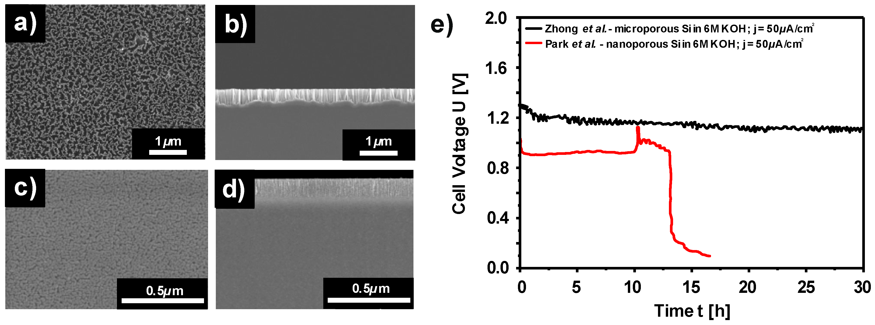
- Zhong, X.; Zhang, H.; Liu, Y.; Bai, J.; Liao, L.; Huang, Y.; Duan, X. High-Capacity Silicon-Air Battery in Alkaline Solution. ChemSusChem 2012, 5, 177–180. [Google Scholar] [CrossRef]
- Park, D.-W.; Kim, S.; Ocon, J.D.; Abrenica, G.H.A.; Lee, J.K.; Lee, J. Controlled Electrochemical Etching of Nanoporous Si Anodes and Its Discharge Behavior in Alkaline Si—Air Batteries. ACS Appl. Mater. Interfaces 2015, 7, 3126–3132. [Google Scholar] [CrossRef] [PubMed]
- Gilliam, R.; Graydon, J.; Kirk, D.; Thorpe, S. A review of specific conductivities of potassium hydroxide solutions for various concentrations and temperatures. Int. J. Hydrog. Energy 2007, 32, 359–364. [Google Scholar] [CrossRef]
- Finne, R.M.; Klein, D.L. A Water-Amine-Complexing Agent System for Etching Silicon. J. Electrochem. Soc. 1967, 114, 965–970. [Google Scholar] [CrossRef]
- Palik, E.D. A Raman Study of Etching Silicon in Aqueous KOH. J. Electrochem. Soc. 1983, 130, 956–959. [Google Scholar] [CrossRef]
- Palik, E.D.; Bermudez, V.M.; Glembocki, O.J. Ellipsometric study of orientation-dependent etching of silicon in aqueous KOH. J. Electrochem. Soc. 1985, 132, 871–884. [Google Scholar] [CrossRef]
- Glembocki, O.J. Bias-Dependent Etching of Silicon in Aqueous KOH. J. Electrochem. Soc. 1985, 132, 145–151. [Google Scholar] [CrossRef]
- Palik, E.D. Study of Bias-Dependent Etching of Si in Aqueous KOH. J. Electrochem. Soc. 1987, 134, 404–409. [Google Scholar] [CrossRef]
- Seidel, H. Anisotropic Etching of Crystalline Silicon in Alkaline Solutions—Part II. J. Electrochem. Soc. 1990, 137, 3626–3632. [Google Scholar] [CrossRef]
- Glembocki, O.J.; Palik, E.D.; Deguel, G.R.; Kendall, D.L. Hydration model for the molarity dependence of the etch rate of Si in aqueous alkali hydroxides. J. Electrochem. Soc. 1991, 138, 1055–1063. [Google Scholar] [CrossRef]
- Allongue, P.; Brune, H.; Gerischer, H. In situ STM observations of the etching of n-Si(111) in NaOH solutions. Surf. Sci. 1992, 275, 414–423. [Google Scholar] [CrossRef]
- Allongue, P.; Costa-Kieling, V.; Gerischer, H. Etching of Silicon in NaOH Solutions II. Electrochemical Studies of n-Si(111) and (100) and Mechanism of the Dissolution. J. Electrochem. Soc. 1993, 140, 1018–1026. [Google Scholar] [CrossRef]
- Inoishi, A.; Sakai, T.; Ju, Y.-W.; Ida, S.; Ishihara, T. A rechargeable Si-air solid state oxygen shuttle battery incorporating an oxide ion conductor. J. Mater. Chem. A 2013, 1, 15212–15215. [Google Scholar] [CrossRef]
- Cohn, G.; Altberg, A.; Macdonald, D.D.; Ein-Eli, Y. A silicon-air battery utilizing a composite polymer electrolyte. Electrochim. Acta 2011, 58, 161–164. [Google Scholar] [CrossRef]
- Garamoun, A.; Schubert, M.B.; Werner, J.H. Thin-Film Silicon for Flexible Metal-Air Batteries. ChemSusChem 2014, 7, 3272–3274. [Google Scholar] [CrossRef] [PubMed]
- Cohn, G.; Macdonald, D.D.; Ein-Eli, Y. Remarkable Impact of Water on the Discharge Performance of a Silicon-Air Battery. ChemSusChem 2011, 4, 1124–1129. [Google Scholar] [CrossRef] [PubMed]
- Jakes, P.; Cohn, G.; Ein-Eli, Y.; Scheiba, F.; Ehrenberg, H.; Eichel, R.-A. Limitation of Discharge Capacity and Mechanisms of Air-Electrode Deactivation in Silicon-Air Batteries. ChemSusChem 2012, 5, 2278–2285. [Google Scholar] [CrossRef] [PubMed]
- Cohn, G.; Eichel, R.A.; Ein-Eli, Y. New insight into the discharge mechanism of silicon-air batteries using electrochemical impedance spectroscopy. Phys. Chem. Chem. Phys. 2013, 15, 3256–3263. [Google Scholar] [CrossRef] [PubMed]
- Iler, R.K. The Chemistry of Silica; Wiley: New York, NY, USA, 1979; ISBN 978-0-471-02404-0. [Google Scholar]
- Bilinski, H.; Ingri, N.; Salomaa, P.; Bloom, G.; Hagen, G. A Determination of the Formation Constant of SiO(OH)3. Acta Chem. Scand. 1967, 21, 2503–2510. [Google Scholar] [CrossRef]
- Pourbaix, M. Silicon. In Atlas of Electrochemical Equilibria in Aqueous Solution; NACE-International: Houston, TX, USA, 1974; pp. 458–463. [Google Scholar]
- Nikolaychuk, P.A. The Revised Pourbaix Diagram for Silicon. Silicon 2014, 6, 109–116. [Google Scholar] [CrossRef]
- Bean, K.E. Anisotropic etching of silicon. IEEE Trans. Electron Devices 1978, 25, 1185–1193. [Google Scholar] [CrossRef]
- Kendall, D.L. Vertical Etching of Silicon at very High Aspect Ratios. Annu. Rev. Mater. Sci. 1979, 9, 373–403. [Google Scholar] [CrossRef]
- Palik, E.D. Study of the Etch-Stop Mechanism in Silicon. J. Electrochem. Soc. 1982, 129, 2051–2059. [Google Scholar] [CrossRef]
- Palik, E.D.; Glembocki, O.J.; Rinko, J.D.; Heard, I. Current-Voltage Characteristics of Heavily Doped p-Si in Aqueous KOH. J. Electrochem. Soc. 1989, 136, 1420–1425. [Google Scholar] [CrossRef]
- Butler, J.A.V. Studies in heterogeneous equilibria. Part III. A kinetic theory of reversible oxidation potentials at inert electrodes. Trans. Faraday Soc. 1924, 19, 734–739. [Google Scholar] [CrossRef]
- Erdey-Gruz, T.; Volmer, M. The theory of hydrogen high tension. Z. Für Phys. Chem. 1930, 150, 203–213. [Google Scholar]
- Wagner, C.; Traud, W.E. The analysis of corrosion procedures through the interaction of electrochemical partial procedures and on the potential difference of mixed electrodes. Z. Für ElektroChem. Und Angew. Phys. Chem. 1938, 44, 391–402. [Google Scholar]
- Palik, E.D.; Glembocki, O.J.; Heard, I.; Burno, P.S.; Tenerz, L. Etching roughness for (100) silicon surfaces in aqueous KOH. J. Appl. Phys. 1991, 70, 3291–3300. [Google Scholar] [CrossRef]
- Zhong, X.; Qu, Y.; Lin, Y.-C.; Liao, L.; Duan, X. Unveiling the Formation Pathway of Single Crystalline Porous Silicon Nanowires. ACS Appl. Mater. Interfaces 2011, 3, 261–270. [Google Scholar] [CrossRef]
- Engelhardt, V.G.; Zeigan, D.; Jancke, H.; Wieker, W. 29Si-NMR spectroscopy of silicate solutions. 2. On the dependence of the structure of silicate anions in water solutions from the Na:Si ratio. Z. Für Anorg. Und Allg. Chem. 1975, 418, 17–28. [Google Scholar] [CrossRef]
- Engelhardt, G.; Altenburg, W.; Hoebbel, D.; Wieker, W. 29Si-NMR-Spektroskopie an Silicatlösungen. IV. Untersuchungen zur Kondensation der Monokieselsäure. Z. Für Anorg. Und Allg. Chem. 1977, 428, 43–52. [Google Scholar] [CrossRef]
- Harris, R.K.; O’Connor, M.J.; Curzon, E.H.; Howarth, O.W. Two-dimensional silicon-29 NMR studies of aqueous silicate solutions. J. Magn. Reson. 1984, 57, 115–122. [Google Scholar] [CrossRef]
- Harris, R.K.; Knight, C.T.G. Silicon-29 nuclear magnetic resonance studies of aqueous silicate solutions. Part 5. First-order patterns in potassium silicate solutions enriched with silicon-29. J. Chem. Soc. Faraday Trans. 2 1983, 79, 1525–1538. [Google Scholar] [CrossRef]
- Harris, R.K.; Knight, C.T.G. Silicon-29 nuclear magnetic resonance studies of aqueous silicate solutions. Part 6. Second-order patterns in potassium silicate solutions enriched with silicon-29. J. Chem. Soc. Faraday Trans. 2 1983, 79, 1539–1561. [Google Scholar] [CrossRef]
- Raz, O.; Starosvetsky, D.; Tsuda, T.; Nohira, T.; Hagiwara, R.; Ein-Eli, Y. Macroporous Silicon Formation on n-Si in Room-Temperature Fluorohydrogenate Ionic Liquid. Electrochem. Solid State Lett. 2007, 10, D25–D28. [Google Scholar] [CrossRef]
- Tsuda, T.; Nohira, T.; Amezawa, K.; Hachiya, K.; Hagiwara, R.; Raz, O.; Ein-Eli, Y. Anodic electrode reaction of p-type silicon in 1-ethyl-3-methylimidazolium fluorohydrogenate room-temperature ionic liquid. Electrochim. Acta 2008, 53, 3650–3655. [Google Scholar] [CrossRef]
- Aslanbas, Ö.; Durmus, Y.E.; Tempel, H.; Hausen, F.; Ein-Eli, Y.; Eichel, R.A.; Kungl, H. Electrochemical analysis and mixed potentials theory of ionic liquid based Metal-Air batteries with Al/Si alloy anodes. Electrochim. Acta 2018, 276, 399–411. [Google Scholar] [CrossRef]
- Read, J. Characterization of the Lithium/Oxygen Organic Electrolyte Battery. J. Electrochem. Soc. 2002, 149, A1190–A1195. [Google Scholar] [CrossRef]
- Read, J.; Mutolo, K.; Ervin, M.; Behl, W.; Wolfenstine, J.; Driedger, A.; Foster, D. Oxygen Transport Properties of Organic Electrolytes and Performance of Lithium/Oxygen Battery. J. Electrochem. Soc. 2003, 150, A1351–A1356. [Google Scholar] [CrossRef]
- Jackovitz, J.F.; Bayles, G.A. Iron Electrode Batteries. In Handbook of Batteries; Linden, D., Reddy, T.B., Eds.; McGraw-Hill: New York, NY, USA, 2002; ISBN 0071359788. pp. 720–746. [Google Scholar]
- Liu, X.; Dai, L. Carbon-based metal-free catalysts. Nat. Rev. Mater. 2016, 1, 16064. [Google Scholar] [CrossRef]
- Ravikumar, M.K.; Sundar Rajan, A.; Sampath, S.; Priolkar, K.R.; Shukla, A.K. In Situ Crystallographic Probing on Ameliorating Effect of Sulfide Additives and Carbon Grafting in Iron Electrodes. J. Electrochem. Soc. 2015, 162, A2339–A2350. [Google Scholar] [CrossRef]
- Vijayamohanan, K.; Balasubramanian, T.S.; Shukla, A.K. Rechargeable alkaline iron electrodes. J. Power Sour. 1991, 34, 269–285. [Google Scholar] [CrossRef]
- Hang, B.T.; Thang, D.H.; Kobayashi, E. Fe/carbon nanofiber composite materials for Fe-air battery anodes. J. Electroanal. Chem. 2013, 704, 145–152. [Google Scholar] [CrossRef]
- Manohar, A.K.; Malkhandi, S.; Yang, B.; Yang, C.; Surya Prakash, G.K.; Narayanan, S.R. A High-Performance Rechargeable Iron Electrode for Large-Scale Battery-Based Energy Storage. J. Electrochem. Soc. 2012, 159, A1209–A1214. [Google Scholar] [CrossRef]
- Weinrich, H.; Gehring, M.; Tempel, H.; Kungl, H.; Eichel, R.-A. Impact of the charging conditions on the discharge performance of rechargeable iron-anodes for alkaline iron-air batteries. J. Appl. Electrochem. 2018, 48, 451–462. [Google Scholar] [CrossRef]
- Hang, B.T.; Watanabe, T.; Eashira, M.; Okada, S.; Yamaki, J.; Hata, S.; Yoon, S.-H.; Mochida, I. The electrochemical properties of Fe2O3-loaded carbon electrodes for iron-air battery anodes. J. Power Sour. 2005, 150, 261–271. [Google Scholar] [CrossRef]
- Li, F.; Shangguan, E.; Li, J.; Li, L.; Yang, J.; Chang, Z.; Li, Q.; Yuan, X.-Z.; Wang, H. Influence of annealing temperature on the structure and electrochemical performance of the Fe3O4 anode material for alkaline secondary batteries. Electrochim. Acta 2015, 178, 34–44. [Google Scholar] [CrossRef]
- Sundar Rajan, A.; Ravikumar, M.K.; Priolkar, K.R.; Sampath, S.; Shukla, A.K. Carbonyl-Iron Electrodes for Rechargeable-Iron Batteries. Electrochem. Energy Technol. 2014, 1, 2–9. [Google Scholar] [CrossRef]
- Öjefors, L. An iron-air vehicle battery. J. Power Sour. 1977, 2, 287–296. [Google Scholar] [CrossRef]
- Bryant, W.A. The structure and performance of sintered iron electrodes. Electrochim. Acta 1979, 24, 1057–1060. [Google Scholar] [CrossRef]
- Micka, K.; Zabransky, Z. Study of Iron Oxide Electrodes in an Alkaline. J. Power Sour. 1987, 19, 315–323. [Google Scholar] [CrossRef]
- Vijayamohanan, K.; Shukla, A.K.; Sathyanarayana, S. Kinetics of electrode reactions occurring on porous iron electrodes in alkaline media. J. Electroanal. Chem. Interfacial Electrochem. 1990, 295, 59–70. [Google Scholar] [CrossRef]
- Periasamy, P.; Ramesh Babu, B.; Venkatakrishna Iyer, S. Performance characterization of sintered iron electrodes in nickel/iron alkaline batteries. J. Power Sour. 1996, 62, 9–14. [Google Scholar] [CrossRef]
- Kitamura, H.; Zhao, L.; Hang, B.T.; Okada, S.; Yamaki, J. Effect of binder materials on cycling performance of Fe2O3 electrodes in alkaline solution. J. Power Sour. 2012, 208, 391–396. [Google Scholar] [CrossRef]
- Gil Posada, J.O.; Hall, P.J. Multivariate investigation of parameters in the development and improvement of NiFe cells. J. Power Sour. 2014, 262, 263–269. [Google Scholar] [CrossRef]
- Kitamura, H.; Zhao, L.; Hang, B.T.; Okada, S.; Yamaki, J. Effect of Charge Current Density on Electrochemical Performance of Fe/C Electrodes in Alkaline Solutions. J. Electrochem. Soc. 2012, 159, A720–A724. [Google Scholar] [CrossRef]
- Vijayamohanan, K.; Shukia, A.K.; Sathyanarayana, S. Role of sulphide additives on the performance of alkaline iron electrodes. J. Electroanal. Chem. Interfacial Electrochem. 1990, 289, 55–68. [Google Scholar] [CrossRef]
- Hang, B.T.; Watanabe, T.; Egashira, M.; Watanabe, I.; Okada, S.; Yamaki, J. The effect of additives on the electrochemical properties of Fe/C composite for Fe/air battery anode. J. Power Sour. 2006, 155, 461–469. [Google Scholar] [CrossRef]
- Wang, Q.; Wang, Y. Overcoming the Limiting Step of Fe2O3 Reduction via in Situ Sulfide Modification. ACS Appl. Mater. Interfaces 2016, 8, 10334–10342. [Google Scholar] [CrossRef]
- Posada, J.O.G.; Hall, P.J. The Effect of Electrolyte Additives on the Performance of Iron Based Anodes for NiFe Cells. J. Electrochem. Soc. 2015, 162, A2036–A2043. [Google Scholar] [CrossRef]
- Öjefors, L. Self-discharge of the alkaline iron-electrode. Electrochim. Acta 1976, 21, 263–266. [Google Scholar] [CrossRef]
- See, D.M.; White, R.E. Temperature and Concentration Dependence of the Specific Conductivity of Concentrated Solutions of Potassium Hydroxide. J. Chem. Eng. Data 1997, 42, 1266–1268. [Google Scholar] [CrossRef]
- Beverskog, B.; Puigdomenech, I. Revised Diagrams for Iron At 25–300 °C. Corros. Sci. 1996, 38, 2121–2135. [Google Scholar] [CrossRef]
- Pourbaix, M. Iron. In Atlas of Electrochemical Equilibria in Aqueous Solution; NACE-International: Houston, TX, USA, 1974; pp. 307–321. [Google Scholar]
- Macdonald, D.D. Passivity—The key to our metals-based civilization. Pure Appl. Chem. 1999, 71, 951–978. [Google Scholar] [CrossRef]
- Vijayamohanan, K.; Shukla, A.K.; Sathyanarayana, S. Open-circuit potential—Time transients of alkaline porous iron electrodes at various states-of-charge. Electrochim. Acta 1991, 36, 369–380. [Google Scholar] [CrossRef]
- McCafferty, E. Kinetics of Corrosion. In Introduction to Corrosion Science; Springer: New York, NY, USA, 2010; ISBN 1441904549. pp. 117–171. [Google Scholar]
- McCafferty, E. Getting started on the basics. In Introduction to Corrosion Science; Springer: New York, NY, USA, 2010; ISBN 1441904549. pp. 13–31. [Google Scholar]
- Berndt, D.; Spahrbier, D. Batteries, 1. General. In Ullmann’s Encyclopedia of Industrial Chemistry; Wiley-VCH Verlag GmbH & Co. KGaA: Weinheim, Germany, 2014; ISBN 9783527306732. pp. 1–23. [Google Scholar]
- Manohar, A.K.; Yang, C.; Malkhandi, S.; Prakash, G.K.S.; Narayanan, S.R. Enhancing the Performance of the Rechargeable Iron Electrode in Alkaline Batteries with Bismuth Oxide and Iron Sulfide Additives. J. Electrochem. Soc. 2013, 160, A2078–A2084. [Google Scholar] [CrossRef]
- Umeda, A.; Nukuna, Y. Secondary Iron-Air Batteries with Acidic Electrolytic Solutions. JP 2010140736, 2010. [Google Scholar]
- Xie, X.; Holze, R. Experimental methods in corrosion research. ChemTexts 2018, 4, 5. [Google Scholar] [CrossRef]
- Cohen, M. Thin Oxide Films on Iron. J. Electrochem. Soc. 1974, 121, 191C–197C. [Google Scholar] [CrossRef]
- Haupt, S.; Strehblow, H.H. Corrosion, layer formation, and oxide reduction of passive iron in alkaline solution: A combined electrochemical and surface analytical study. Langmuir 1987, 3, 873–885. [Google Scholar] [CrossRef]
- Oelkrug, D.; Fritz, M.; Stauch, H. Topology of Iron Surfaces in the Early Stages of Electrochemical Corrosion. J. Electrochem. Soc. 1992, 139, 2419–2424. [Google Scholar] [CrossRef]
- Müller-Zülow, B.; Kipp, S.; Lacmann, R.; Schneeweiss, M.A. Topological aspects of iron corrosion in alkaline solution by means of scanning force microscopy (SFM). Surf. Sci. 1994, 311, 153–158. [Google Scholar] [CrossRef]
- Schmuki, P.; Büchler, M.; Virtanen, S.; Isaacs, H.S.; Ryan, M.P.; Böhni, H. Passivity of iron in alkaline solutions studied by in-situ XANES and a laser reflection technique. J. Electrochem. Soc. 1999, 146, 2097–2102. [Google Scholar] [CrossRef]
- Jayalakshmi, N.; Muralidharan, V.S. Electrochemical behaviour of iron oxide electrodes in alkali solutions. J. Power Sour. 1990, 32, 277–286. [Google Scholar] [CrossRef]
- Stern, M.; Geaby, A.L. Electrochemical Polarization. J. Electrochem. Soc. 1957, 104, 56–63. [Google Scholar] [CrossRef]
- Dražić, D.M.; Hao, C.S. The anodic dissolution process on active iron in alkaline solutions. Electrochim. Acta 1982, 27, 1409–1415. [Google Scholar] [CrossRef]
- Ord, J.L. The Anodic Oxidation of Iron: Overpotential Analysis for a Two-Phase Film. J. Electrochem. Soc. 1976, 123, 1876–1882. [Google Scholar] [CrossRef]
- Periasamy, P.; Ramesh Babu, B.; Iyer, S.V. Electrochemical behaviour of Teflon-bonded iron oxide electrodes in alkaline solutions. J. Power Sour. 1996, 63, 79–85. [Google Scholar] [CrossRef]
- McCafferty, E. Passivity. In Introduction to Corrosion Science; Springer: New York, NY, USA, 2010; ISBN 1441904549. pp. 209–262. [Google Scholar]
- Oblonsky, L.J.; Davenport, A.J.; Ryan, M.P.; Isaacs, H.S.; Newman, R.C. In situ x-ray absorption near edge structure study of the potential dependence of the formation of the passive film on iron in borate buffer. J. Electrochem. Soc. 1997, 144, 2398–2404. [Google Scholar] [CrossRef]
- Armstrong, R.D.; Baurhoo, I. The dissolution of iron in concentrated alkali. J. Electroanal. Chem. Interfacial Electrochem. 1972, 40, 325–338. [Google Scholar] [CrossRef]
- Schrebler Guzmán, R.S.; Vilche, J.R.; Arvía, A.J. The potentiodynamic behaviour of iron in alkaline solutions. Electrochim. Acta 1979, 24, 395–403. [Google Scholar] [CrossRef]
- Bard, A.J.; Faulkner, L.R. Potential Sweep Methods. In Electrochemcial Methods—Fundamental and Application; John Wiley& Sons Inc.: New York, NY, USA, 2001; pp. 244–278. [Google Scholar]
- Černý, J.; Micka, K. Voltammetric study of an iron electrode in alkaline electrolytes. J. Power Sour. 1989, 25, 111–122. [Google Scholar] [CrossRef]
- Posada, J.O.G.; Hall, P.J. Post-hoc comparisons among iron electrode formulations based on bismuth, bismuth sulphide, iron sulphide, and potassium sulphide under strong alkaline conditions. J. Power Sour. 2014, 268, 810–815. [Google Scholar] [CrossRef]
- Cnobloch, H.; Gröppel, D.; Nippe, W.; Von Sturm, F. Eisen-Elektroden für Metall/Luft-Zellen. Chem. Ing. Tech. 1973, 45, 203–206. [Google Scholar] [CrossRef]
- Tschinkel, W.; Neugebauer, H.; Neckel, A. In Situ FTIR Spectroscopy of Iron Electrodes in Alkaline Solutions II. External Reflection Absorption Spectroscopy. J. Electrochem. Soc. 1990, 137, 1475–1480. [Google Scholar] [CrossRef]
- Weinrich, H.; Come, J.; Tempel, H.; Kungl, H.; Eichel, R.-A.; Balke, N. Understanding the nanoscale redox-behavior of iron-anodes for rechargeable iron-air batteries. Nano Energy 2017, 41, 706–716. [Google Scholar] [CrossRef]
- Andersson, B.; Öjefors, L. Slow Potentiodynamic Studies of Porous Alkaline Iron Electrodes. J. Electrochem. Soc. 1976, 123, 824–828. [Google Scholar] [CrossRef]
- Vijayamohanan, K.; Shukla, A.K.; Sathyanarayana, S. Formation mechanism of porous iron electrodes. J. Power Sour. 1990, 32, 329–339. [Google Scholar] [CrossRef]
- Neugebauer, H.; Tschinkel, W.; Nauer, G.; Neckel, A. In-situ FTIR spectroscopy of iron electrodes. Mikrochim. Acta 1988, 94, 269–272. [Google Scholar] [CrossRef]
- Monteiro, J.F.; Ivanova, Y.A.; Kovalevsky, A.V.; Ivanou, D.K.; Frade, J.R. Reduction of magnetite to metallic iron in strong alkaline medium. Electrochim. Acta 2016, 193, 284–292. [Google Scholar] [CrossRef]
- Yamamoto, Y. Electrochemical Behavior of Iron Electrodes in Alkaline Solutions II. Activation of Electrode. Denki Kagaku 1992, 8, 725–728. [Google Scholar]
- Casellato, U.; Comisso, N.; Mengoli, G. Effect of Li ions on reduction of Fe oxides in aqueous alkaline medium. Electrochim. Acta 2006, 51, 5669–5681. [Google Scholar] [CrossRef]
- Hang, B.T.; Thang, D.H.; Nga, N.T.; Le Minh, P.T.; Kobayashi, E. Nanoparticle Fe2O3-Loaded Carbon Nanofibers as Iron-Air Battery Anodes. J. Electrochem. Soc. 2013, 160, A1442–A1445. [Google Scholar] [CrossRef]
- Yamamoto, Y. Electrochemical behavior of iron electrodes in alkaline solutions I. Effect of electrolyte concentration. Denki Kagaku 1992, 60, 721–724. [Google Scholar]
- Hang, B.T.; Hayashi, H.; Yoon, S.-H.; Okada, S.; Yamaki, J. Fe2O3-filled carbon nanotubes as a negative electrode for an Fe-air battery. J. Power Sour. 2008, 178, 393–401. [Google Scholar] [CrossRef]
- Geronov, Y.; Tomov, T.; Georgiev, S. Mössbauer spectroscopy investigation of the iron electrode during cycling in alkaline solution. J. Appl. Electrochem. 1975, 5, 351–358. [Google Scholar] [CrossRef]
- Černý, J.; Jindra, J.; Micka, K. Comparative study of porous iron electrodes. J. Power Sour. 1993, 45, 267–279. [Google Scholar] [CrossRef]
- Posada, J.O.G.; Hall, P.J. Controlling hydrogen evolution on iron electrodes. Int. J. Hydrogen Energy 2016, 41, 20807–20817. [Google Scholar] [CrossRef]
- Kabanov, B.; Burstein, R.; Frumkin, A. The kinetics of electrode processes on the iron electrode. Disc. Faraday Soc. 1947, 1, 259–269. [Google Scholar] [CrossRef]
- Hang, B.T.; Watanabe, T.; Egashira, M.; Watanabe, I.; Okada, S.; Yamaki, J.-I. Comparative Study of Fe2O3-Nanoloaded Carbon and Fe2O3-Nano/Carbon Mixed Composites for Iron-Air Battery Anodes. Electrochem. Solid-State Lett. 2005, 8, A476–A480. [Google Scholar] [CrossRef]
- Manohar, A.K.; Yang, C.; Malkhandi, S.; Yang, B.; Surya Prakash, G.K.; Narayanan, S.R. Understanding the Factors Affecting the Formation of Carbonyl Iron Electrodes in Rechargeable Alkaline Iron Batteries. J. Electrochem. Soc. 2012, 159, A2148–A2155. [Google Scholar] [CrossRef]
- Öjefors, L. Temperature Dependence of Iron and Cadmium Alkaline Electrodes. J. Electrochem. Soc. 1976, 123, 1139–1144. [Google Scholar] [CrossRef]
- Armstrong, R.D.; Baurhoo, I. Solution Soluble Species in the Operation of the Iron Electrode in Alkaline Solution. Electroanal. Chem. Interfacial Electrochem. 1971, 34, 41–46. [Google Scholar]
- Sikora, E.; Macdonald, D.D. The Passivity of Iron in the Presence of Ethylenediaminetetraacetic Acid, I. General Electrochemical Behavior. J. Electrochem. Soc. 2000, 147, 4087–4092. [Google Scholar] [CrossRef]
- Huang, Z.Q.; Ord, J.L. An optical study of the iron electrode in alkaline electrolyte. J. Electrochem. Soc. 1985, 132, 24–28. [Google Scholar] [CrossRef]
- Ryan, M.P.; Toney, M.F.; Davenport, A.J.; Oblonsky, L.J. In situ X-ray-diffraction studies of passive oxide films. MRS Bull. 1999, 24, 29–35. [Google Scholar] [CrossRef]
- Neugebauer, H.; Moser, A.; Strecha, P.; Neckel, A. In Situ FTIR Spectroscopy of Iron Electrodes in Alkaline Solutions I. Internal Reflection Spectroscopy. J. Electrochem. Soc. 1990, 137, 1472–1475. [Google Scholar] [CrossRef]
- Díez-Pérez, I.; Gorostiza, P.; Sanz, F.; Müller, C. First Stages of Electrochemical Growth of the Passive Film on Iron. J. Electrochem. Soc. 2001, 148, B307–B313. [Google Scholar] [CrossRef]
- Rajan, A.S.; Sampath, S.; Shukla, A.K. An in situ carbon-grafted alkaline iron electrode for iron-based accumulators. Energy Environ. Sci. 2014, 7, 1110–1116. [Google Scholar] [CrossRef]
- Figueredo Rodriguez, H.A.; Mckerracher, R.D.; Ponce De León, C.; Walsh, F.C. Improvement of Negative Electrodes for Iron-Air Batteries: Comparison of Different Iron Compounds as Active Materials. J. Electrochem. Soc. 2019, 166, A107–A117. [Google Scholar] [CrossRef]
- Öjefors, L. SEM Studies of Discharge Products from Alkaline Iron Electrodes. J. Electrochem. Soc. 1976, 123, 1691–1696. [Google Scholar] [CrossRef]
- Hayashi, K.; Wada, Y.; Maeda, Y.; Suzuki, T.; Sakamoto, H.; Tan, W.K.; Kawamura, G.; Muto, H.; Matsuda, A. Electrochemical Performance of Sintered Porous Negative Electrodes Fabricated with Atomized Powders for Iron-Based Alkaline Rechargeable Batteries. J. Electrochem. Soc. 2017, 164, A2049–A2055. [Google Scholar] [CrossRef]
- Tong, C.S.; Wang, S.D.; Wang, Y.Y.; Wan, C.C. A Study of the Iron Electrode Structure of Ni-Fe Cell. J. Electrochem. Soc. 1982, 129, 1173–1180. [Google Scholar] [CrossRef]
- Comisso, N.; Mengoli, G. Electrochemical investigations on composite iron electrodes. J. Appl. Electrochem. 2007, 37, 949–959. [Google Scholar] [CrossRef]
- Hariprakash, B.; Martha, S.K.; Hegde, M.S.; Shukla, A.K. A sealed, starved-electrolyte nickel-iron battery. J. Appl. Electrochem. 2005, 35, 27–32. [Google Scholar] [CrossRef]
- Long, N.V.; Yang, Y.; Thi, C.M.; Hang, B.T.; Cao, Y.; Nogami, M. Controlled synthesis and characterization of iron oxide micro-particles for Fe-air battery electrode material. Colloid Polym. Sci. 2015, 293, 49–63. [Google Scholar] [CrossRef]
- Huo, G.; Lu, X.; Huang, Y.; Li, W.; Liang, G. Electrochemical Performance of α-Fe2O3 Particles as Anode Material for Aqueous Rechargeable Batteries. J. Electrochem. Soc. 2014, 161, A1144–A1148. [Google Scholar] [CrossRef]
- Shangguan, E.; Guo, L.; Li, F.; Wang, Q.; Li, J.; Li, Q.; Chang, Z.; Yuan, X.-Z. FeS anchored reduced graphene oxide nanosheets as advanced anode material with superior high-rate performance for alkaline secondary batteries. J. Power Sour. 2016, 327, 187–195. [Google Scholar] [CrossRef]
- Kim, T.; Ohata, Y.; Kim, J.; Rhee, C.K.; Miyawaki, J.; Yoon, S.-H. Fe nanoparticle entrained in tubular carbon nanofiber as an effective electrode material for metal-air batteries: A fundamental reason. Carbon 2014, 80, 698–707. [Google Scholar] [CrossRef]
- Vassie, P.R.; Tseung, A.C.C. High performance, rechargeable sintered iron electrodes—I: The effect of preparative methods and additives on the structure and performance of sintered iron electrodes. Electrochim. Acta 1976, 21, 299–302. [Google Scholar] [CrossRef]
- Chamoun, M.; Skårman, B.; Vidarsson, H.; Smith, R.I.; Hull, S.; Lelis, M.; Milcius, D.; Noréus, D. Stannate Increases Hydrogen Evolution Overpotential on Rechargeable Alkaline Iron Electrodes. J. Electrochem. Soc. 2017, 164, A1251–A1257. [Google Scholar] [CrossRef]
- Shangguan, E.; Fu, S.; Wu, C.; Cai, X.; Li, J.; Chang, Z.; Wang, Z.; Li, Q. Sublimed sulfur powders as novel effective anode additives to enhance the high-rate capabilities of iron anodes for advanced iron-based secondary batteries. Electrochim. Acta 2019, 301, 162–173. [Google Scholar] [CrossRef]
- Macdonald, D.D.; Owen, D. The Electrochemistry of Iron in 1M Lithium Hydroxide Solution at 22° and 200°C. J. Electrochem. Soc. 1973, 120, 317–324. [Google Scholar] [CrossRef]
- Paulraj, A.R.; Kiros, Y.; Chamoun, M.; Svengren, H.; Nor, D. Electrochemical Performance and in Operando Charge Efficiency Measurements of Cu/Sn-Doped Nano Iron Electrodes. Batteries 2019, 5, 1. [Google Scholar] [CrossRef]
- Weinrich, H.; Gehring, M.; Tempel, H.; Kungl, H.; Eichel, R.-A. Electrode thickness-dependent formation of porous iron electrodes for secondary alkaline iron-air batteries. Electrochim. Acta 2019, 314, 61–71. [Google Scholar] [CrossRef]


| System | Primary Reaction | n | Full Cell Voltage | Mass Density (Metal) | Specific Energy (Metal) | Energy Density (Metal) | Mass Density (Dis. Product) | Specific Energy | Energy Density | Ref. |
|---|---|---|---|---|---|---|---|---|---|---|
| ––––––––––––––– Excluding Oxygen Uptake ––––––––––––––– | –––––– Including Oxygen Uptake ––––– | |||||||||
| [V] | [kg/L] | [Wh/kg] | [Wh/L] | [kg/L] | [Wh/kg] | [Wh/L] | ||||
| Fe-air | Fe ⇌ Fe(OH)2 | 2 * | 1.28 | 7.87 | 1229 | 9677 | 3.40 | 764 | 2598 | [43] |
| Zn-air | Zn ⇌ ZnO | 2 * | 1.65 | 7.14 | 1352 | 9653 | 5.61 | 1086 | 6092 | [44] |
| K-O2 | K → KO2 | 1 ✝ | 2.48 | 0.89 | 1700 | 1513 | 2.16 | 935 | 2019 | [45] |
| Na-O2 | Na → Na2O2 | 1 ✝ | 2.33 | 0.97 | 2716 | 2634 | 2.81 | 1601 | 4409 | [46] |
| Na → NaO2 | 1 ✝ | 2.27 | 2646 | 2567 | 2.20 | 1106 | 2433 | [47] | ||
| Ca-O2 | Ca → CaO2 | 2 ✝ | 3.38 | 1.54 | 4520 | 6961 | 2.9 | 2516 | 7296 | [48,49] |
| Ca → CaO | 2 ✝ | 3.13 | 4186 | 6446 | 3.34 | 2996 | 10007 | |||
| Mg-Air | Mg → Mg(OH)2 | 2 * | 2.77 | 1.74 | 6098 | 10610 | 2.37 | 2848 | 6750 | [50] |
| Mg-O2 | Mg → MgO | 2 ✝ | 2.95 | 6493 | 11299 | 3.6 | 3919 | 14108 | [51] | |
| Si-air | Si →Si(OH)4 | 4 * | 2.09 | 2.33 | 8001 | 18644 | ~1.8 | 2334 | 4201 | [52] |
| Si → SiO2 | 4 ✝ | 2.21 | 8461 | 19748 | 2.19 | 3947 | 8643 | [53] | ||
| Al-air | Al →Al(OH)3 | 3 * | 2.71 | 2.70 | 8091 | 21837 | 2.42 | 2784 | 6737 | [54] |
| Al-O2 | Al (⇌) Al2O3 | 3 ✝ | ~2.1 | ~6258 | ~16897 | 3.97 | 3311 | 13145 | [55] | |
| Li-O2 | Li (⇌) Li2O2 | 1 ✝ | 2.96 | 0.53 | 11430 | 6104 | 2.31 | 3458 | 7988 | [40,41] |
| Li-O2 | Li (⇌) Li2O | 1 ✝ | 2.91 | 11238 | 6001 | 2.01 | 5220 | 10492 | ||
| System | Discharge Product | Full Cell Voltage | Specific Energy | Energy Density | Reported Specific Energy | Reported Reversibility | |||
|---|---|---|---|---|---|---|---|---|---|
| ––––––––––––––– Theoretical Values ––––––––––––––– | ––––––––––––––– Experimental Results ––––––––––––––– | ||||||||
| Performance | Condition | Ref. | Cycles | Ref. | |||||
| [V] | [Wh/kg] | [Wh/L] | |||||||
| Fe-air | Fe(OH)2 | 1.28 | 1229 | 9677 | 453 Wh/kgFe | [b,c,d,e] | [95] | 3500 [b,d] | [100] |
| Zn-air | ZnO | 1.65 | 1352 | 9653 | >700 Wh/kgZn | [a,c,d] | [94] | >75 [a,c] | [97] |
| K-O2 | KO2 | 2.48 | 1700 | 1513 | ~19,500 Wh/kgC | [a,c,d] | [101] | >200 [a,c] | [101] |
| Na-O2 | Na2O2 | 2.33 | 2716 | 2634 | ~18,300 Wh/kgC | [a,c,d] | [46,47] | >20 [a,c] | [102] |
| NaO2 | 2.27 | 2646 | 2567 | ||||||
| Ca-O2 | CaO2 | 3.38 | 4520 | 6961 | tbd | - | - | tbd | [44,45] |
| CaO | 3.13 | 4186 | 6446 | ||||||
| Mg-Air | Mg(OH)2 | 2.77 | 6098 | 10610 | ~2750 Wh/kgCath. | [a,c,d,f] | [103,104] | <10 [a,c,d] | [51] |
| Mg-O2 | MgO | 2.95 | 6493 | 11299 | |||||
| Si-air | Si(OH)4 | 2.09 | 8001 | 18644 | ~1600 Wh/kgSi | [a,c,d] | [52] | not yet | [50] |
| SiO2 | 2.21 | 8461 | 19748 | ||||||
| Al-air | Al(OH)3 | 2.71 | 8091 | 21837 | ~2300 Wh/kgAl | [a,c,d] | [55] | limited | [92,100] |
| Al-O2 | Al2O3 | ~2.1 | ~6258 | ~16897 | |||||
| Li-O2 | Li2O2 | 2.96 | 11430 | 6104 | >11,000 Wh/kgC | [a,c,d] | [41,105] | >250 [a,c] | [98] |
| Li-O2 | Li2O | 2.91 | 11238 | 6001 | |||||
| Types | Electrolyte | Cell Reactions | Remarks | Ref. |
|---|---|---|---|---|
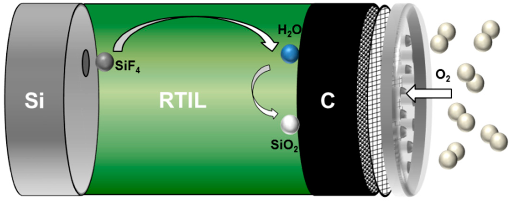
| Non-Aqueous | EMIm(HF)2.3F | Si + 12(HF)2F− ⇄ SiF4 + 8(HF)3F− + 4e− O2 + 12(HF)3F− + 4e− ⇄ 2H2O + 16(HF)2F− SiF4 + 2H2O + 4(HF)2F− ⇄ SiO2 + 4(HF)3F− Si + O2 ⇄ SiO2 | Higher energy densities and lower corrosion rates compared to aqueous systems. Discharge limitation mainly by Si anode as well as pore clogging and catalyst conversion problems in the air cathode. Environmental concerns due to fluoride content and high cost. No rechargeability. | [53,123,142,143,144] |
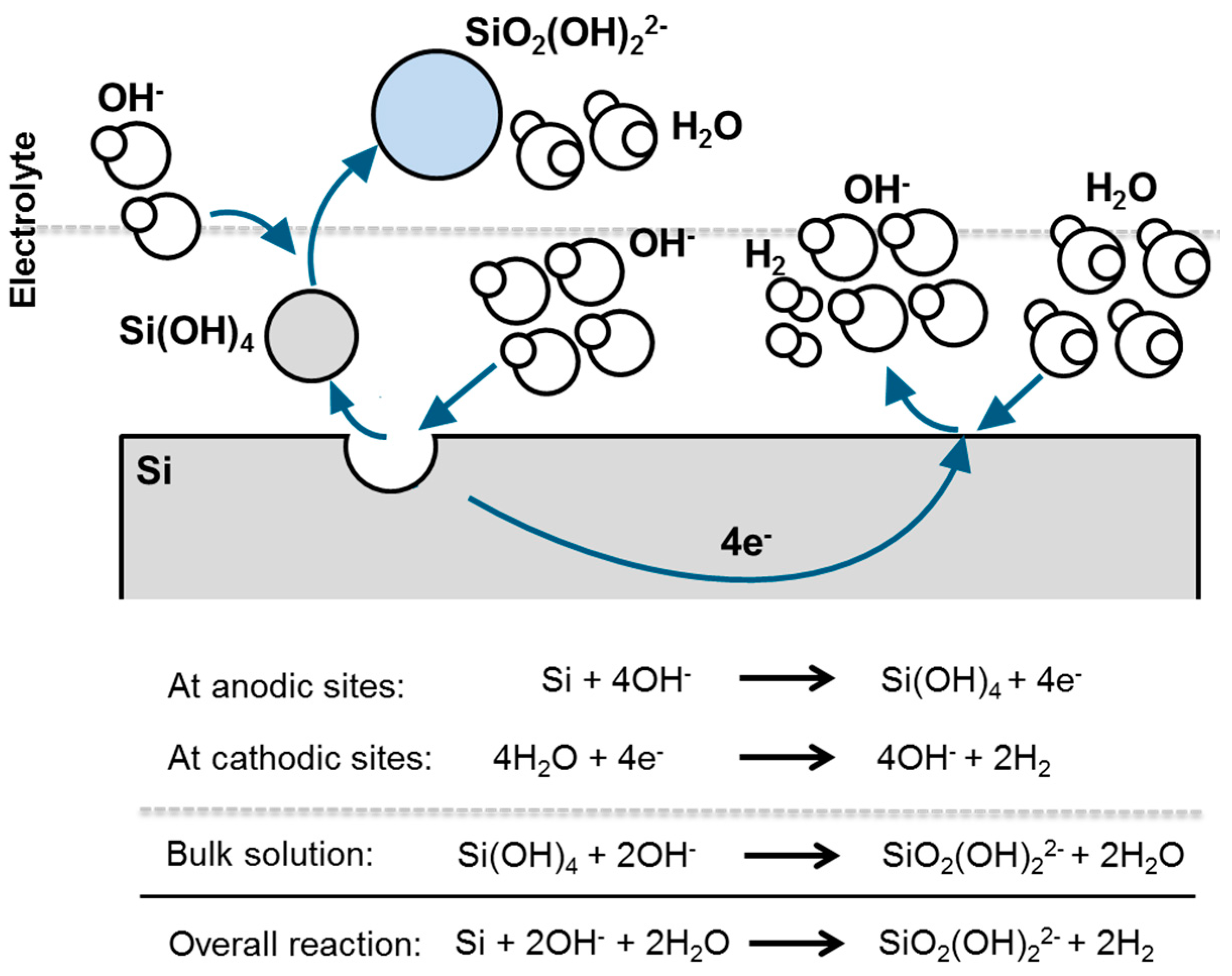
| Aqueous | KOH | Si + 4OH− ⇄ Si(OH)4 + 4e− Si(OH)4 + 2OH− → SiO2(OH)22− + 2H2O O2 + 2H2O + 4e−⇄4OH− Si + 2OH− + 2H2O → SiO2(OH)22− + 2H2 | Cost effective, environmentally friendly, easy handling, high ionic conductivity. Higher corrosion rates, low mass conversion efficiencies, and no rechargeability. | [127,128] |
| Solid State | Stabilized zirconia (CSZ) | 2O2− ⇄ O2 + 4e− 2Si + O2 ⇄ 2SiO Si + O2 ⇄ SiO2 O2 + 4e− ⇄ 2O2− | Rechargeability with round-trip efficiency of 45%. Full active mass consumption of Si anode. High working temperature, low energy density | [139] |
| Gel polymer electrolyte (EMIm(HF)2.3F) | See non-aqueous | Mechanically strong and flexible GPE, extended discharge times, no drying out. Lower ionic conductivity, lower discharge voltages. | [140] |
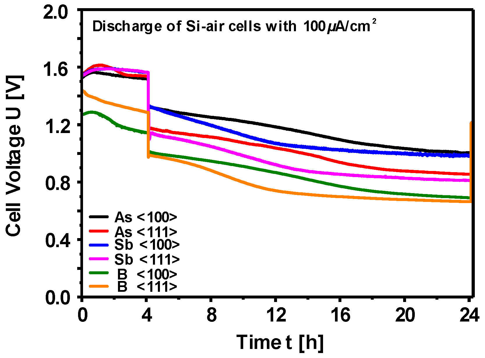
| Si Wafer Type | Discharge Voltage [V] | Corrosion Rate [nm/min] | Mass Conversion Efficiency [%] | Specific Energy [Wh/kg] |
|---|---|---|---|---|
| As<100> | 1.05 | 3.6 | 30.5 | 1350.2 |
| As<111> | 0.86 | 2.0 | 43.6 | 1660.5 |
| Sb<100> | 0.98 | 3.7 | 29.7 | 1230.3 |
| Sb<111> | 0.81 | 2.3 | 40.6 | 1430.6 |
| B<100> | 0.69 | 1.9 | 44.3 | 1340.1 |
| B<111> | 0.66 | 1.8 | 47.2 | 1370.8 |
| Electrode Concept | Material (size) | Precursor | Preparation | Current Collector | Additives (wt.-%) | Formation | Dis. Capacity (Chr. Capacity) | Reversibility | Ref. |
|---|---|---|---|---|---|---|---|---|---|
| Sheets | Fe (continuous) | None | Polishing | None | None | Yes | 6.8 µAh/cm2 (200 µAh/cm2) | Full-cell > 8 cycles | [221] |
| Microparticles | Fe (3–5 µm) | None | Die pressing (after 140 °C) | None | 8.5% Bi2S3; 5% PE | Yes | 220 mAh/gFe (300 mAh/gFe) | >350 cycles | [174] |
| Microparticles | Fe (3–5 µm) | None | (Hot-) pressed at 140 °C | Nickel grid | 10% Bi2O3; 5% FeS; 10% PE; 10% K2CO3 | Yes | 240 mAh/gFe (500 mAh/gFe) | > 1200 cycles | [109] |
| Microparticles | Fe (3–5 µm) | None | Coating of current collector & short sintering | Nickel mesh | 10% graphite; 1% Bi2S3; 6% PTFE; 0.5% NiSO4·7H2O | Yes | 400 mAh/gFe (500 mAh/gFe) | >200 cycles | [177] |
| Microparticles | Fe (<10 µm) | None | Coating of current collector | Nickel foam | 11% FeS; 6% PTFE; LiOH; K2S | Yes | 230 mAh/gFe (550 mAh/gFe) | >50 cycles | [233] |
| Sintered Electrodes | Fe (3–5 µm) | Carbonyl Iron | Sintering in Ar at 850 °C | Nickel mesh | NH4HCO3; Na2S | Yes | 192 mAh/gFe (200 mAh/gFe) | >3500 cycles | [100] |
| Nanoparticles | Fe/Fe3O4 (not specified) | α-FeC2O4 2H2O–PVA composite | Combustion of precur. & coating of current collector | Nickel mesh | 10% carbon; 1% Bi2S3; 6% PTFE; 0.5% NiSO4·7H2O | No | 400 mAh/g (500 mAh/g) | >100 cycles | [244] |
| Nanoparticles | Fe2O3 (15–50 nm) | FeCl2 | Hot pressed at 200 °C | Two steel meshes | 10% carbon; 4% Bi2S3; 5% PTFE | No | 400 mAh/g (900 mAh/g) | Full-cell >20 cycles | [96] |
| Nanoparticles | Fe2O3 (<50 nm) | None | Loaded nickel foam | None | Carbon; 10% binder | Yes | <700 mAh/g (1007 mAh/g) | >100 cycles | [230] |
| Nanoparticles on Carbon Structures | Fe2O3 (<50 nm) | Fe(NO3)3 | Rolling of Fe2O3–filled CNT | None | 10% PTFE | No | <500 mAh/g (962 mAh/g) | >30 cycles | [172] |
| Nanoparticles on Carbon Structures | Fe2O3 (<20 nm) | Fe(NO3)3 | Rolling of Fe2O3–filled CNF | None | 10% PTFE; 2% Bi2S3 | No | <550 mAh/g (1007 mAh/g) | >50 cycles | [53] |
| Nanoparticles on Carbon Structures | FeOx/graphene (<100 nm) | Fe(OAc)2 | Loaded nickel foam | Nickel foam | Glucose; PTFE | No | <377 mAh/g (not specified) | >300 cycles | [95] |
| Nanoparticles on Carbon Structures | FeS/graphene oxide (<100 nm) | FeSO4·7H2O | Co-precipitation | Nickel foam | 10% PTFE; 10% carbon black; 3% Bi2S3; 0.5% NiSO4·7H2O | No | <325 mAh/g (400 mAh/g) | >300 cycles | [93] |
| Plane Electrode Sheet | Pressed-Plate Microparticles | Sintered Electrodes | Nano-Particles | Nanoparticle-Loaded Carbon Structures | |
|---|---|---|---|---|---|
| Surface Area | - | 0/+ | +/++ | ++ | ++ |
| Mechanical Stability | ++ | 0/+ | + | - | - |
| Electrical Conductivity | +/++ | 0 | + | -/++ | -/++ |
| Applicability of Elec. Additives | -- | ++ | - | ++ | +/++ |
| Carbon Content | -- | + | -- | ++ | ++ |
| Electrochemical Performance | - | + | ++ | + | 0/+ |
© 2019 by the authors. Licensee MDPI, Basel, Switzerland. This article is an open access article distributed under the terms and conditions of the Creative Commons Attribution (CC BY) license (http://creativecommons.org/licenses/by/4.0/).
Share and Cite
Weinrich, H.; Durmus, Y.E.; Tempel, H.; Kungl, H.; Eichel, R.-A. Silicon and Iron as Resource-Efficient Anode Materials for Ambient-Temperature Metal-Air Batteries: A Review. Materials 2019, 12, 2134. https://doi.org/10.3390/ma12132134
Weinrich H, Durmus YE, Tempel H, Kungl H, Eichel R-A. Silicon and Iron as Resource-Efficient Anode Materials for Ambient-Temperature Metal-Air Batteries: A Review. Materials. 2019; 12(13):2134. https://doi.org/10.3390/ma12132134
Chicago/Turabian StyleWeinrich, Henning, Yasin Emre Durmus, Hermann Tempel, Hans Kungl, and Rüdiger-A. Eichel. 2019. "Silicon and Iron as Resource-Efficient Anode Materials for Ambient-Temperature Metal-Air Batteries: A Review" Materials 12, no. 13: 2134. https://doi.org/10.3390/ma12132134
APA StyleWeinrich, H., Durmus, Y. E., Tempel, H., Kungl, H., & Eichel, R.-A. (2019). Silicon and Iron as Resource-Efficient Anode Materials for Ambient-Temperature Metal-Air Batteries: A Review. Materials, 12(13), 2134. https://doi.org/10.3390/ma12132134