Mechanical Properties and Sulfate Resistance of High Volume Fly Ash Cement Mortars with Air-Cooled Slag as Fine Aggregate and Polypropylene Fibers


Abstract
:1. Introduction
2. Materials and Methods
2.1. Materials
2.2. Mix Proportions
2.3. Fabrication of Specimens and Testing Methods
3. Results
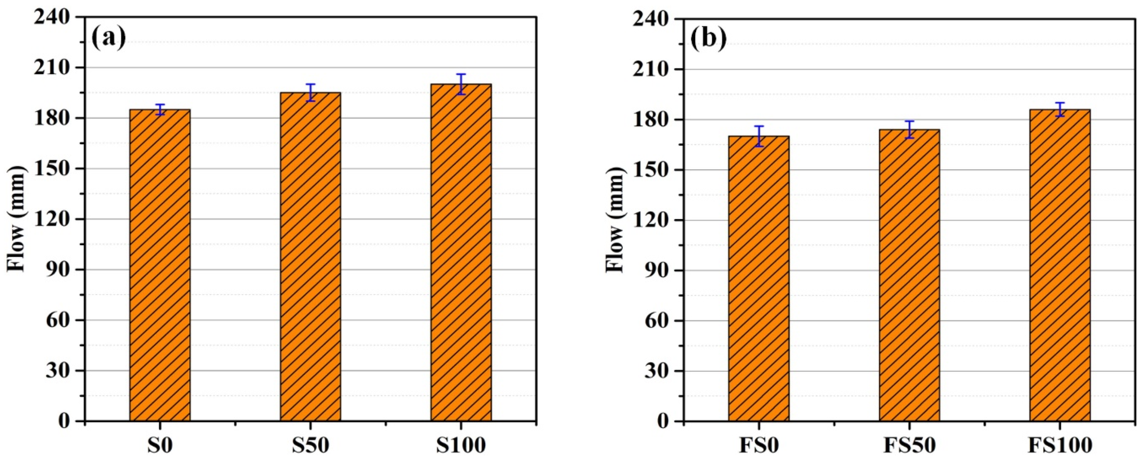
3.1. Flowability
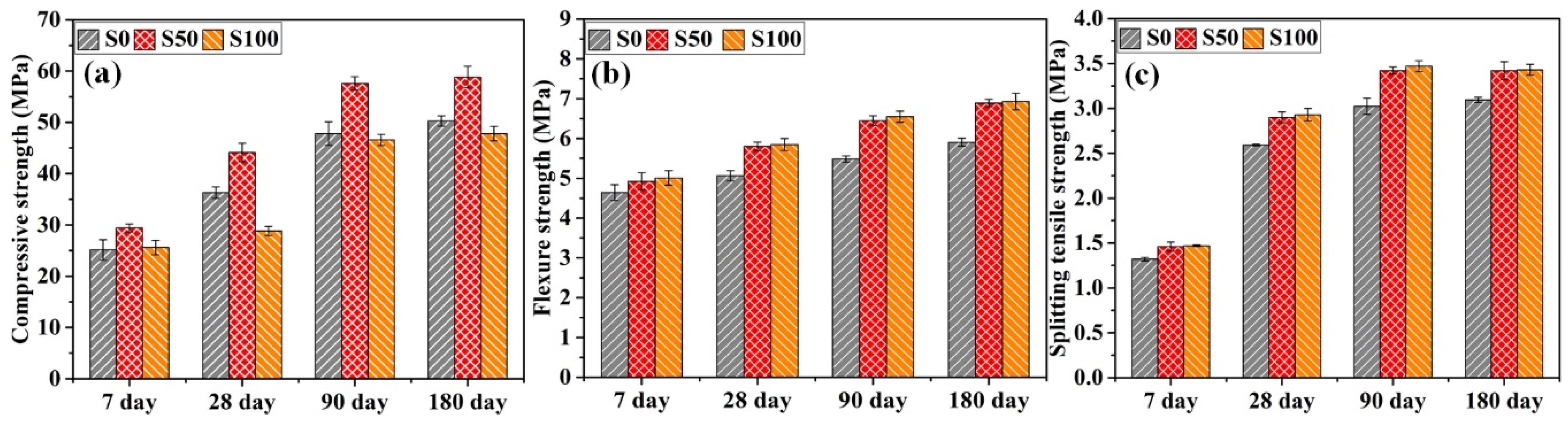
3.2. Mechanical Properties
3.2.1. Mortars without Fiber Addition
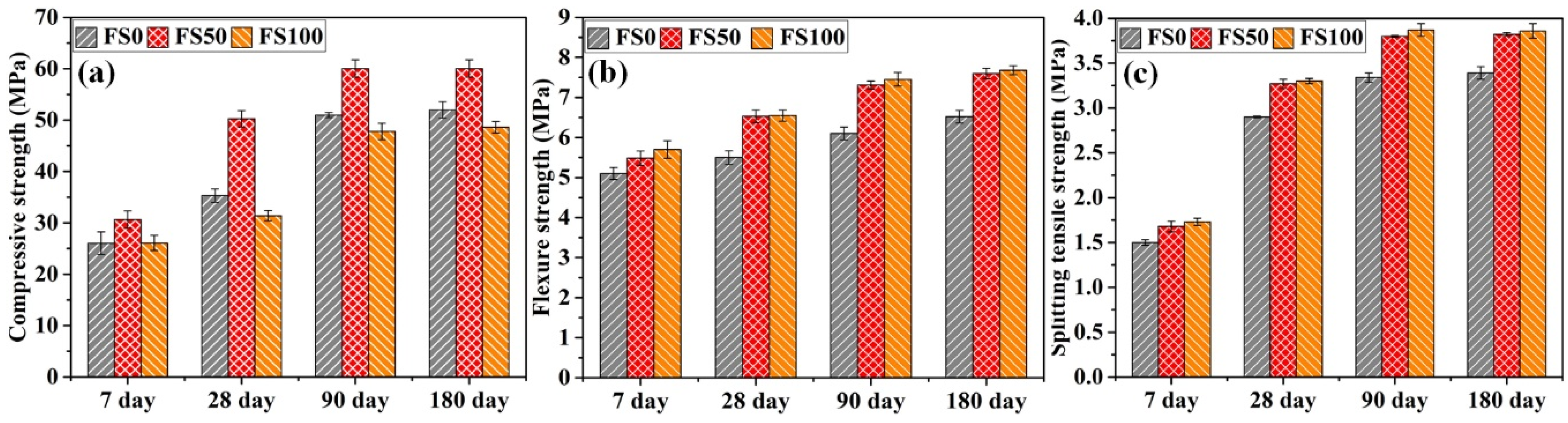
3.2.2. Mortars with Fiber Addition
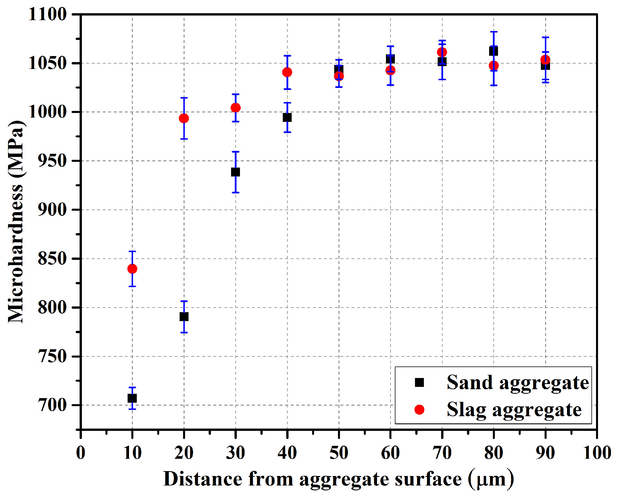
3.3. Microhardness Test
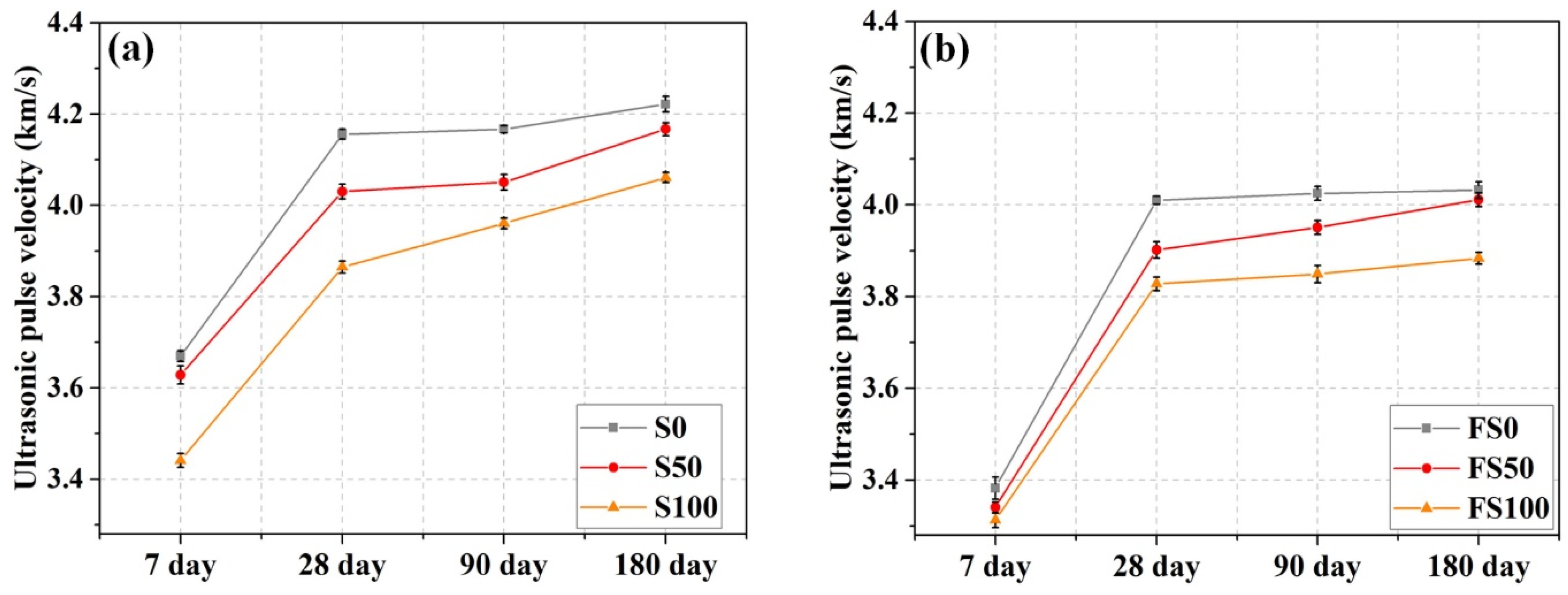
3.4. Ultrasonic Pulse Velocity
3.5. Characteristic Properties in Sulfate Solution
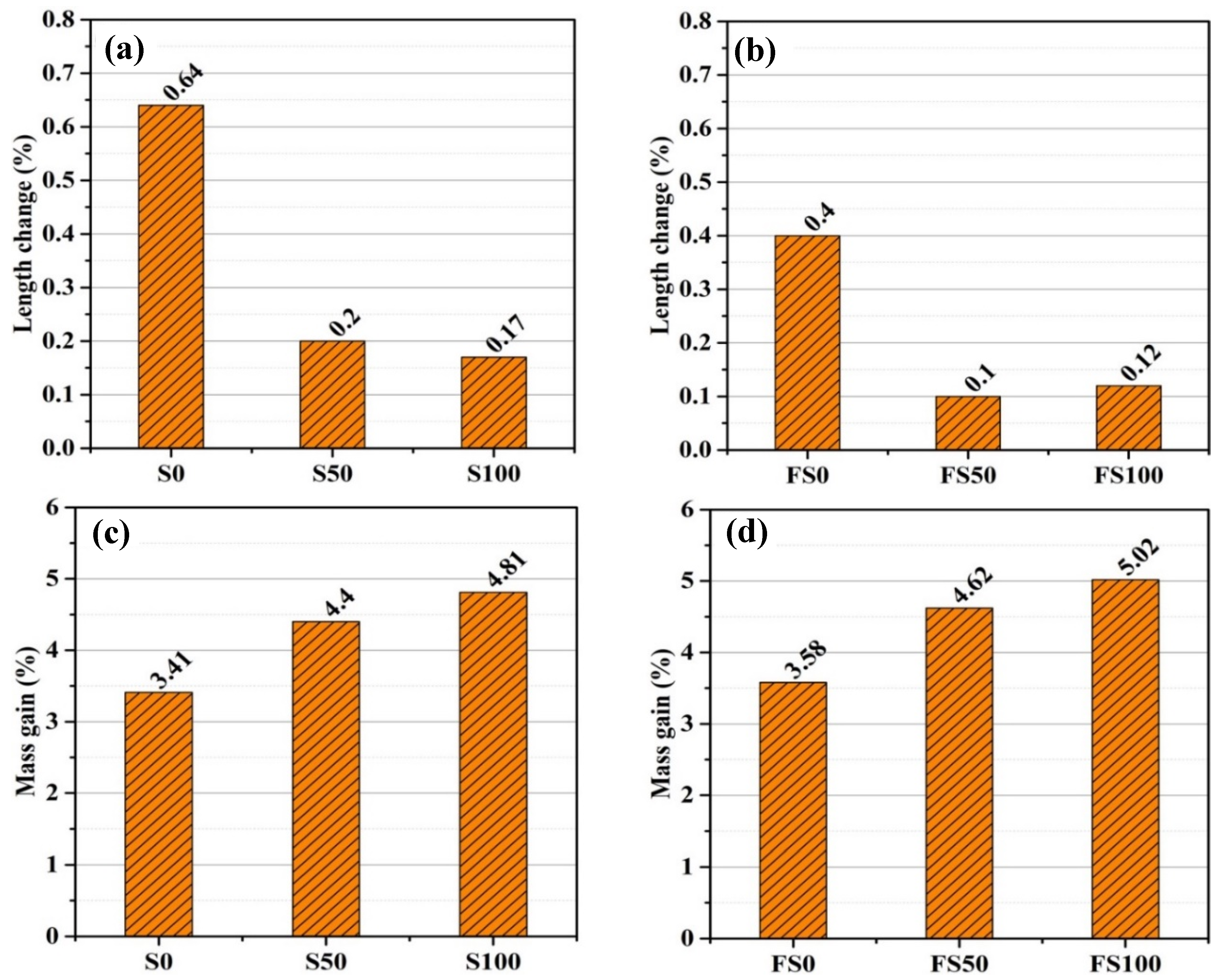
3.5.1. Length and Mass Change
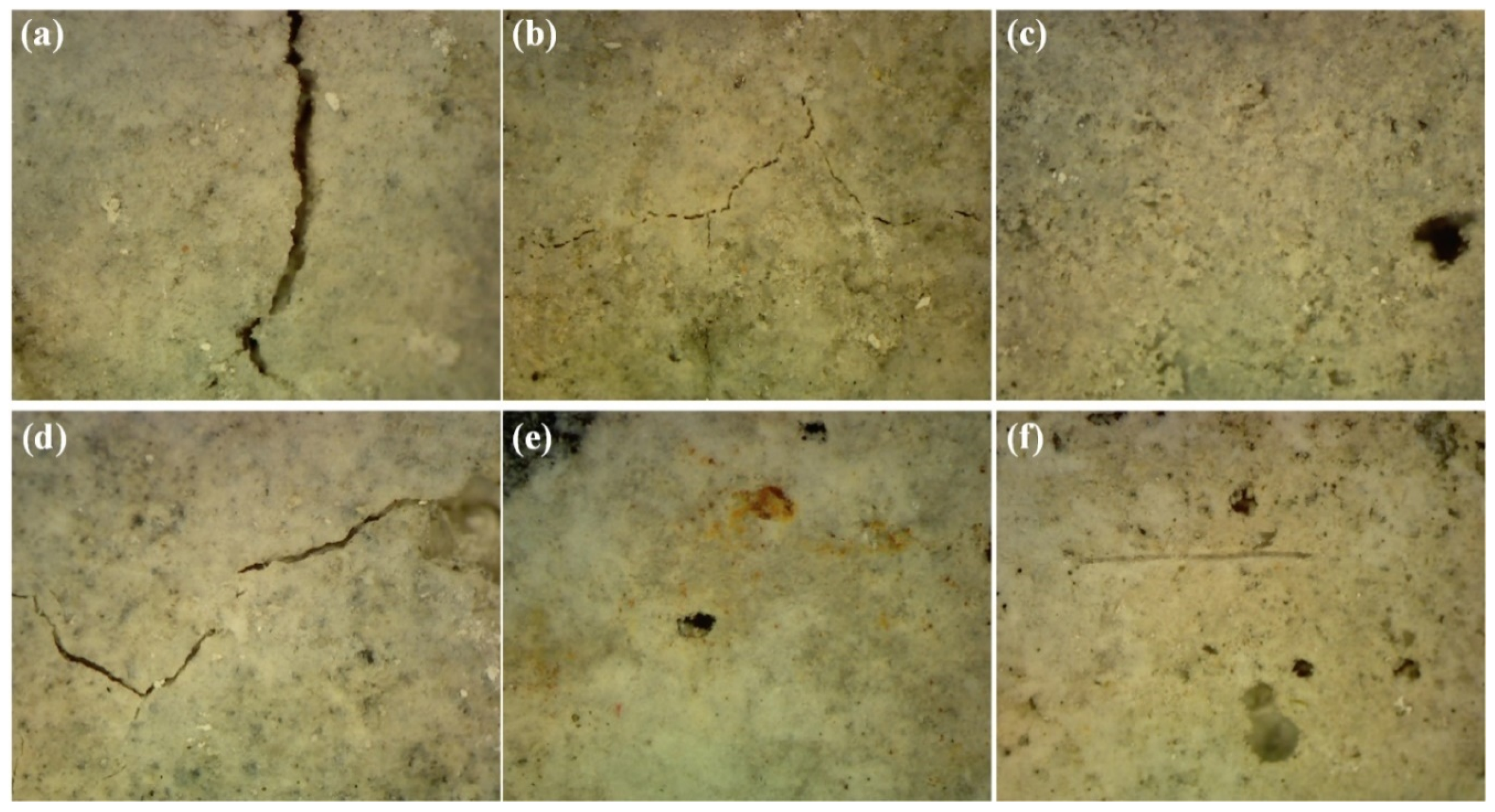
3.5.2. Visual Inspection
3.5.3. Compressive Strength
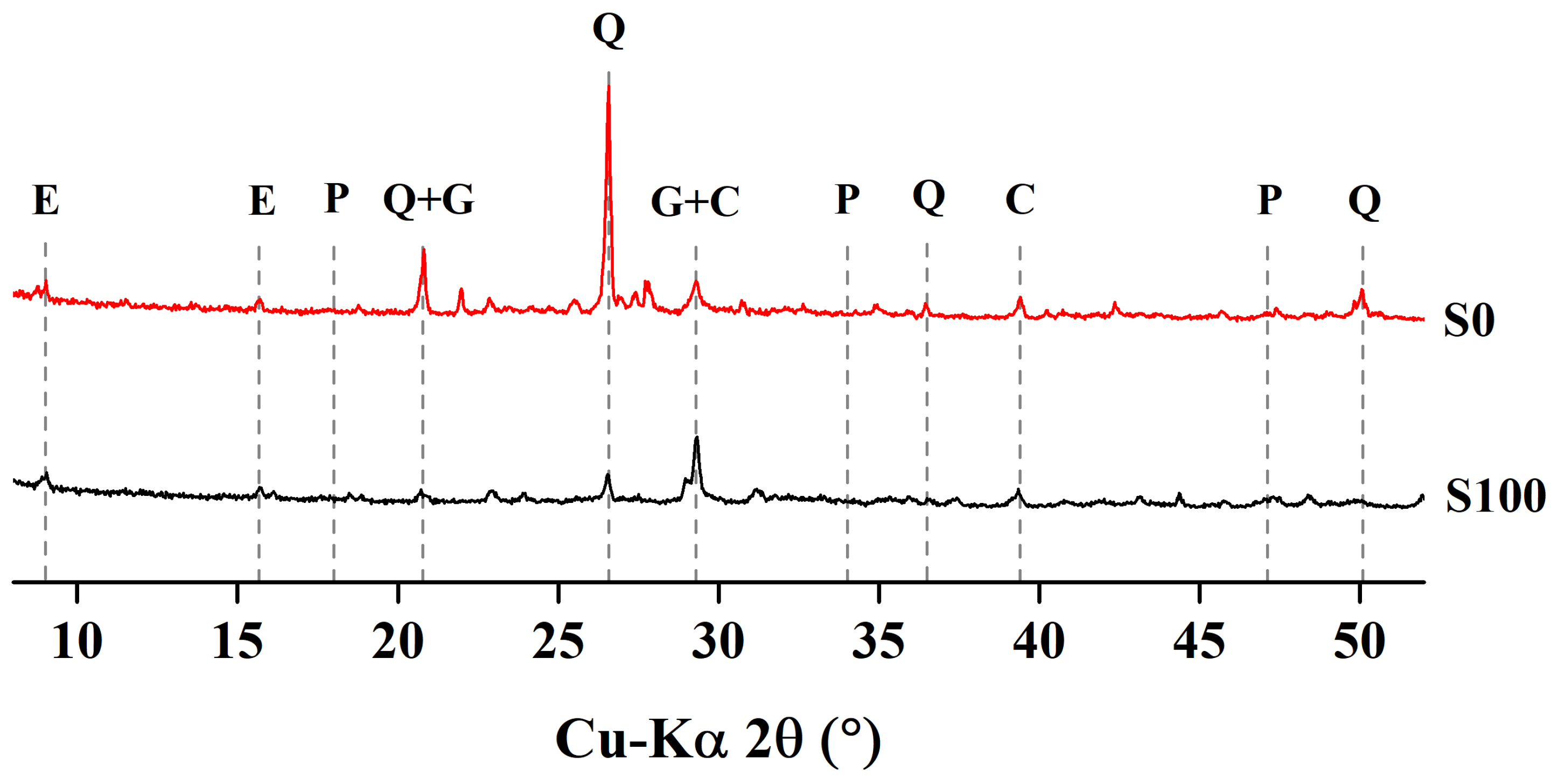
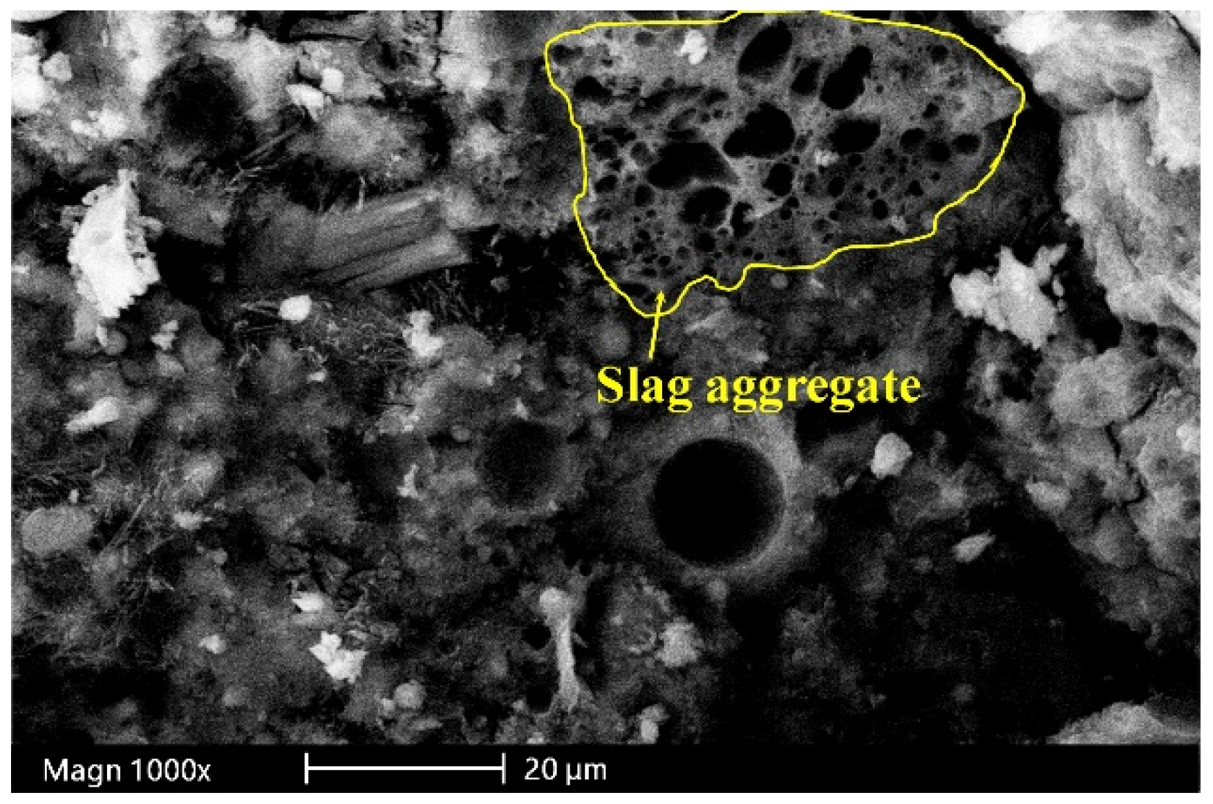
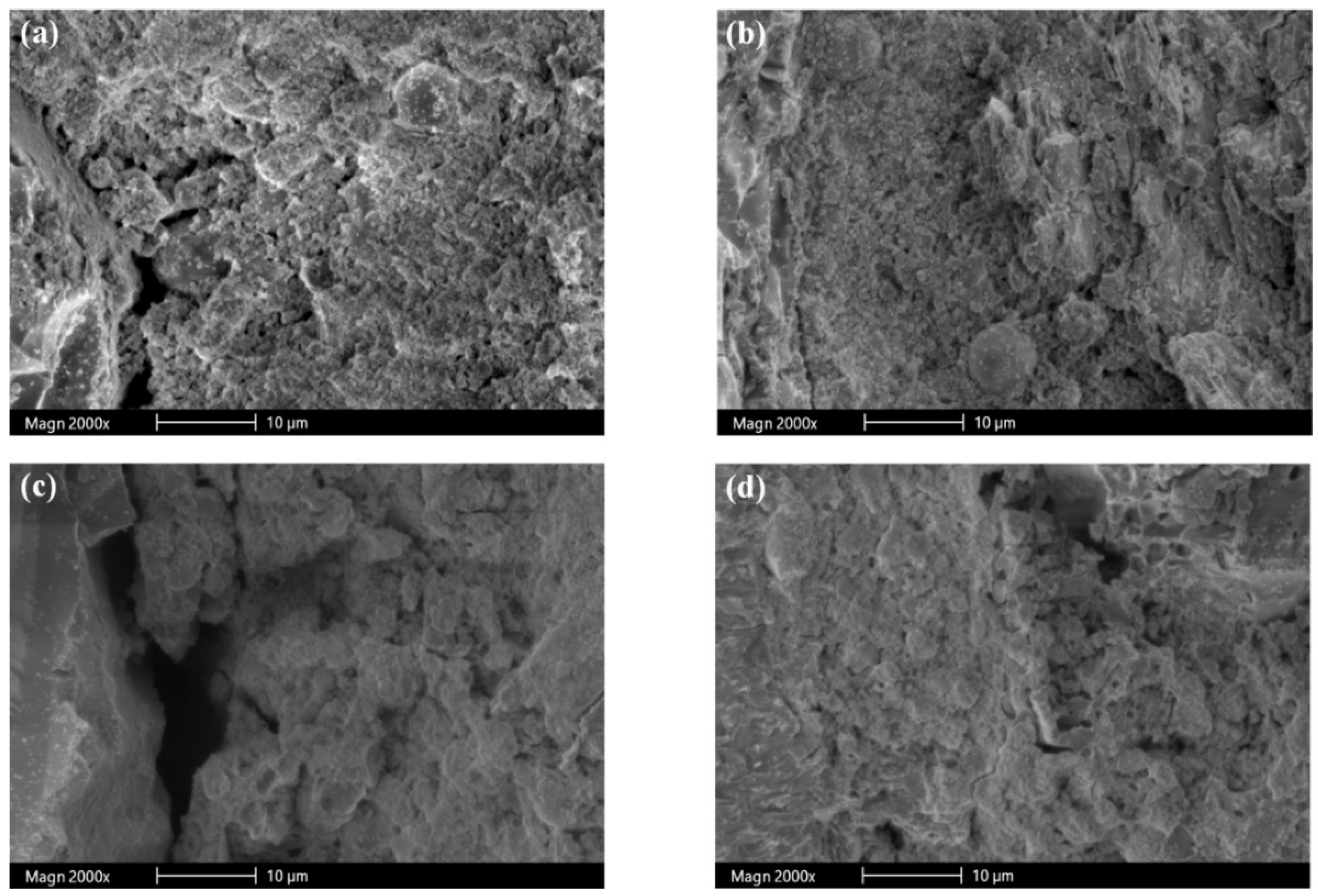
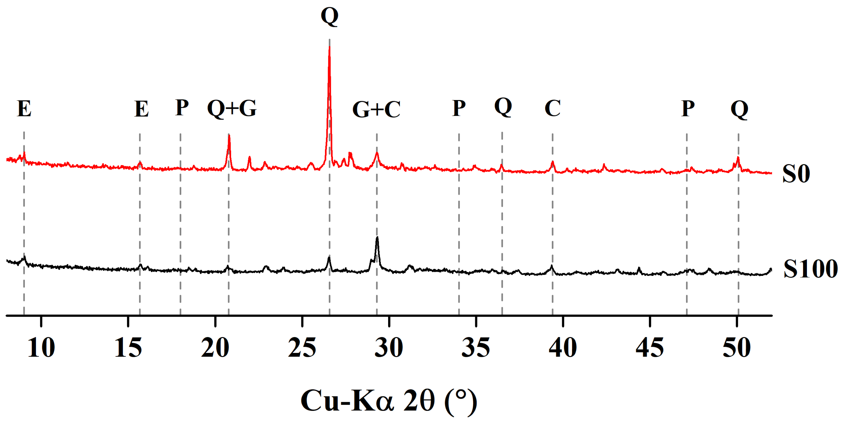
3.6. SEM and XRD Analysis
4. Conclusions
- The inclusion of slag aggregate increases the flow of mortar mixes, while the addition of fiber reduces the flow;
- The incorporation of 50% slag aggregate results in enhanced compressive, flexure, and splitting tensile strength. Strength decreases with a replacement level beyond 50%. The strength values for fiber-reinforced specimens are higher than those for specimens without fiber;
- Slag aggregates provide better packing of cementitious particles near the aggregate surface than sand aggregates provide. Consequently, a dense microstructure in the near aggregate surface for slag specimens is observed;
- The addition of slag aggregate increases the porosity of mortar specimens. This results in lower UPV values;
- Compared to mortar specimens containing only sand as a fine aggregate, slag-incorporated mortar specimens present enhanced performance under sulfate attack. The formation of gypsum and ettringite in the empty voids of slag mortars densifies the microstructure, which results in increased compressive strength.
5. Further Research
Author Contributions
Funding
Conflicts of Interest
References
- Rashad, A.M. A preliminary study on the effect of fine aggregate replacement with metakaolin on strength and abrasion resistance of concrete. Constr. Build. Mater. 2013, 44, 487–495. [Google Scholar] [CrossRef]
- Siddique, R. Waste Materials and by-Products in Concrete; Springer Science & Business Media: Berlin, Germany, 2007. [Google Scholar]
- Ober, J.A.; Strontium, U.S. Geological Survey, Mineral Commodity Summaries. Available online: https://minerals.usgs.gov/minerals/pubs/commodity/iron_&_steel_slag/mcs-2018-fesla.pdf (accessed on 22 January 2019).
- Morian, D.A.; Van Dam, T.; Perera, R. Use of Air-Cooled Blast Furnace Slag as Coarse Aggregate in Concrete Pavements; Federal Highway Administration: Washington, DC, USA, 2012. [Google Scholar]
- Yüksel, İ.; Bilir, T.; Özkan, Ö. Durability of concrete incorporating non-ground blast furnace slag and bottom ash as fine aggregate. Build. Environ. 2007, 42, 2651–2659. [Google Scholar] [CrossRef]
- Valcuende, M.; Benito, F.; Parra, C.; Miñano, I. Shrinkage of self-compacting concrete made with blast furnace slag as fine aggregate. Constr. Build. Mater. 2015, 76, 1–9. [Google Scholar] [CrossRef]
- Etxeberria, M.; Pacheco, C.; Meneses, J.; Berridi, I. Properties of concrete using metallurgical industrial by-products as aggregates. Constr. Build. Mater. 2010, 24, 1594–1600. [Google Scholar] [CrossRef]
- Escalante-Garcia, J.; Magallanes-Rivera, R.; Gorokhovsky, A. Waste gypsum–blast furnace slag cement in mortars with granulated slag and silica sand as aggregates. Constr. Build. Mater. 2009, 23, 2851–2855. [Google Scholar] [CrossRef]
- Zeng, Q.; Li, K.; Fen-chong, T.; Dangla, P. Determination of cement hydration and pozzolanic reaction extents for fly-ash cement pastes. Constr. Build. Mater. 2012, 27, 560–569. [Google Scholar] [CrossRef]
- Sengul, O.; Tasdemir, C.; Mehmet, A.T. Mechanical properties and rapid chloride permeability of concretes with ground fly ash. ACI Mater. J. 2005, 102, 414–421. [Google Scholar]
- Li, G. Properties of high-volume fly ash concrete incorporating nano-SiO2. Cem. Concr. Res. 2004, 34, 1043–1049. [Google Scholar] [CrossRef]
- Supit, S.W.; Shaikh, F.U.; Sarker, P.K. Effect of ultrafine fly ash on mechanical properties of high volume fly ash mortar. Constr. Build. Mater. 2014, 51, 278–286. [Google Scholar] [CrossRef]
- Çavdar, A. Investigation of freeze–thaw effects on mechanical properties of fiber reinforced cement mortars. Compos. Part B Eng. 2014, 58, 463–472. [Google Scholar] [CrossRef]
- Karahan, O.; Atiş, C.D. The durability properties of polypropylene fiber reinforced fly ash concrete. Mater. Des. 2011, 32, 1044–1049. [Google Scholar] [CrossRef]
- Zhang, P.; Li, Q.-F. Effect of polypropylene fiber on durability of concrete composite containing fly ash and silica fume. Compos. Part B Eng. 2013, 45, 1587–1594. [Google Scholar] [CrossRef]
- ASTM. ASTM C150/C150M - 17, Standard Specification for Portland Cement; ASTM: West Conshohocken, PA, USA, 2017. [Google Scholar]
- Langan, B.; Weng, K.; Ward, M. Effect of silica fume and fly ash on heat of hydration of Portland cement. Cem. Concr. Res. 2002, 32, 1045–1051. [Google Scholar] [CrossRef]
- Barbhuiya, S.; Gbagbo, J.; Russell, M.; Basheer, P. Properties of fly ash concrete modified with hydrated lime and silica fume. Constr. Build. Mater. 2009, 23, 3233–3239. [Google Scholar] [CrossRef]
- ASTM. Standard Test Method for Compressive Strength of Hydraulic Cement Mortars (Using 2-in. or [50-mm] Cube Specimens); ASTM: West Conshohocken, PA, USA, 2007. [Google Scholar]
- ASTM. 348: 02. Standard Test Method for Flexural Strength of Hydraulic-Cement Mortars; ASTM: West Conshohocken, PA, USA, 2002. [Google Scholar]
- ASTM. Standard Test Method for Flow of Hydraulic Cement Mortar. C 1437; ASTM: West Conshohocken, PA, USA, 2007. [Google Scholar]
- ASTM. 496/C 496M-04. Standard Test Method for Splitting Tensile Strength of Cylindrical Concrete Specimens; ASTM: West Conshohocken, PA, USA, 2004. [Google Scholar]
- ASTM. 597, Standard Test Method for Pulse Velocity through Concrete; ASTM: West Conshohocken, PA, USA, 2009. [Google Scholar]
- Ferraris, C.; Stutzman, P.; Peltz, M.; Winpigler, J. Developing a more rapid test to assess sulfate resistance of hydraulic cements. J. Res. Natl. Inst. Stand. Technol. 2005, 110, 529. [Google Scholar] [CrossRef]
- Qudoos, A.; Kim, H.G.; Ryou, J.-S. Influence of Titanium Dioxide Nanoparticles on the Sulfate Attack upon Ordinary Portland Cement and Slag-Blended Mortars. Materials 2018, 11, 356. [Google Scholar] [Green Version]
- Hollis, N.; Stephen, D.; Stu, P. Petrographic Methods of Examining Hardened Concrete: A Petrographic Manual; United States Department of Transportation: Washington, DC, USA, 2006.
- Qudoos, A.; Kim, H.G.; Ryou, J.-S. Influence of the surface roughness of crushed natural aggregates on the microhardness of the interfacial transition zone of concrete with mineral admixtures and polymer latex. Construct. Build. Mater. 2018, 168, 946–957. [Google Scholar] [CrossRef]
- Yuksel, I.; Genç, A. Properties of concrete containing nonground ash and slag as fine aggregate. ACI Mater. J. 2007, 104, 397. [Google Scholar]
- Shihada, S. Effect of polypropylene fibers on concrete fire resistance. J. Civ. Eng. Manag. 2011, 17, 259–264. [Google Scholar] [CrossRef]
- Qasrawi, H. The use of steel slag aggregate to enhance the mechanical properties of recycled aggregate concrete and retain the environment. Constr. Build. Mater. 2014, 54, 298–304. [Google Scholar] [CrossRef]
- Topcu, I.B.; Bilir, T. Effect of Non-Ground-Granulated Blast-Furnace Slag as Fine Aggregate on Shrinkage Cracking of Mortars. ACI Mater. J. 2010, 107, 545. [Google Scholar]
- Yuksel, I.; Ozkan, O.; Bilir, T. Use of granulated blast-furnace slag in concrete as fine aggregate. Mater. J. 2006, 103, 203–208. [Google Scholar]
- Aydın, S.; Yazıcı, H.; Baradan, B. High temperature resistance of normal strength and autoclaved high strength mortars incorporated polypropylene and steel fibers. Constr. Build. Mater. 2008, 22, 504–512. [Google Scholar] [CrossRef]
- Song, P.; Hwang, S.; Sheu, B. Strength properties of nylon-and polypropylene-fiber-reinforced concretes. Cem. Concr. Res. 2005, 35, 1546–1550. [Google Scholar] [CrossRef]
- Daneti, S.B.; Wee, T.-H.; Thangayah, T.S.O. Effect of polypropylene fibres on the shrinkage cracking behaviour of lightweight concrete. Mag. Concr. Res. 2011, 63, 871–881. [Google Scholar] [CrossRef]
- Topcu, I.B.; Canbaz, M. Effect of different fibers on the mechanical properties of concrete containing fly ash. Constr. Build. Mater. 2007, 21, 1486–1491. [Google Scholar] [CrossRef]
- Koksal, F.; Gencel, O.; Kaya, M. Combined effect of silica fume and expanded vermiculite on properties of lightweight mortars at ambient and elevated temperatures. Constr. Build. Mater. 2015, 88, 175–187. [Google Scholar] [CrossRef]
- Nik, A.S.; Omran, O.L. Estimation of compressive strength of self-compacted concrete with fibers consisting nano-SiO2 using ultrasonic pulse velocity. Constr. Build. Mater. 2013, 44, 654–662. [Google Scholar]
- Yap, S.P.; Alengaram, U.J.; Jumaat, M.Z. Enhancement of mechanical properties in polypropylene–and nylon–fibre reinforced oil palm shell concrete. Mater. Des. 2013, 49, 1034–1041. [Google Scholar] [CrossRef]
- Ramezanianpour, A.; Esmaeili, M.; Ghahari, S.; Najafi, M. Laboratory study on the effect of polypropylene fiber on durability, and physical and mechanical characteristic of concrete for application in sleepers. Constr. Build. Mater. 2013, 44, 411–418. [Google Scholar] [CrossRef]
- Binici, H.; Durgun, M.Y.; Rızaoğlu, T.; Koluçolak, M. Investigation of durability properties of concrete pipes incorporating blast furnace slag and ground basaltic pumice as fine aggregates. Sci. Iran. 2012, 19, 366–372. [Google Scholar] [CrossRef] [Green Version]
- Lee, S.; Moon, H.; Swamy, R.; Kim, S.; Kim, J. Sulfate attack of mortars containing recycled fine aggregates. ACI Mater. J. 2005, 102, 224. [Google Scholar]


| Composition | Weight (%) | ||
|---|---|---|---|
| OPC | FA | SF | |
| SiO2 | 20.8 | 56.6 | 88.7 |
| Al2O3 | 6.3 | 27.1 | 1.8 |
| Fe2O3 | 3.2 | 4.4 | 1.8 |
| CaO | 62 | 3.8 | 1.5 |
| MgO | 3.3 | 0.8 | 0.8 |
| SO3 | 2.2 | 0.2 | 0.1 |
| Physical properties | - | - | - |
| Specific gravity | 3.15 | 2.23 | 2.2 |
| Specific surface area (cm²/g) | 3200 | 3750 | 20,000 |
| Loss on Ignition (%) | 1.3 | 4.4 | 1.1 |
| Mortar Mix | Compressive Strength (MPa) | |||||
|---|---|---|---|---|---|---|
| 28 Days | 90 Days | 180 Days | ||||
| Water Immersed | Sulfate Immersed | Water Immersed | Sulfate Immersed | Water Immersed | Sulfate Immersed | |
| S0 | 36.3 (3.1) | 37.5 (2.6) | 47.8 (3.3) | 49.2 (2.1) | 50.3 (1.8) | 49.1 (1.3) |
| S50 | 44.1 (2.4) | 48.1 (2.0) | 57.6 (1.7) | 60.7 (1.2) | 58.8 (1.5) | 66.7 (1.6) |
| S100 | 28.8 (1.5) | 34.6 (1.1) | 46.6 (1.8) | 50.6 (2.4) | 47.8 (2.1) | 49.8 (1.4) |
| FS0 | 35.3 (1.1) | 38.8 (1.7) | 51.0 (2.1) | 52.3 (3.2) | 52.0 (1.6) | 51.5 (2.6) |
| FS50 | 50.3 (1.7) | 55.4 (1.5) | 60.1 (2.0) | 64.5 (1.4) | 60.1 (2.2) | 63.1 (1.8) |
| FS100 | 31.4 (2.0) | 37.3 (1.9) | 47.8 (1.5) | 50.7 (1.9) | 48.6 (2.3) | 50.3 (2.0) |
© 2019 by the authors. Licensee MDPI, Basel, Switzerland. This article is an open access article distributed under the terms and conditions of the Creative Commons Attribution (CC BY) license (http://creativecommons.org/licenses/by/4.0/).
Share and Cite
Kim, J.H.; Qudoos, A.; Jakhrani, S.H.; Atta-ur-Rehman; Lee, J.B.; Kim, S.S.; Ryou, J.-S. Mechanical Properties and Sulfate Resistance of High Volume Fly Ash Cement Mortars with Air-Cooled Slag as Fine Aggregate and Polypropylene Fibers. Materials 2019, 12, 469. https://doi.org/10.3390/ma12030469
Kim JH, Qudoos A, Jakhrani SH, Atta-ur-Rehman, Lee JB, Kim SS, Ryou J-S. Mechanical Properties and Sulfate Resistance of High Volume Fly Ash Cement Mortars with Air-Cooled Slag as Fine Aggregate and Polypropylene Fibers. Materials. 2019; 12(3):469. https://doi.org/10.3390/ma12030469
Chicago/Turabian StyleKim, Jun Hyeong, Abdul Qudoos, Sadam Hussain Jakhrani, Atta-ur-Rehman, Jeong Bae Lee, Seong Soo Kim, and Jae-Suk Ryou. 2019. "Mechanical Properties and Sulfate Resistance of High Volume Fly Ash Cement Mortars with Air-Cooled Slag as Fine Aggregate and Polypropylene Fibers" Materials 12, no. 3: 469. https://doi.org/10.3390/ma12030469