RETRACTED: SrFexNi1−xO3−δ Perovskites Coated on Ti Anodes and Their Electrocatalytic Properties for Cleaning Nitrogenous Wastewater

School of Chemical Engineering and Technology, Tianjin University, Tianjin 300350, China
*
Author to whom correspondence should be addressed.
Materials 2019, 12(3), 511; https://doi.org/10.3390/ma12030511
Submission received: 23 January 2019
/
Revised: 30 January 2019
/
Accepted: 3 February 2019
/
Published: 8 February 2019
/
Retracted: 23 October 2023
(This article belongs to the Special Issue New Trends in Semiconductors' Catalytic Application)
Abstract
:Perovskites (ABO3), regarded as the antioxidative anode materials in electrocatalysis to clean nitrogenous wastewater, show limited oxygen vacancies and conductivity due to their traditional semiconductor characteristic. To further improve the conductivity and electrocatalytic activity, the ferrum (Fe) element was first doped into the SrNiO3 to fabricate the SrFexNi1−xO3−δ perovskites, and their optimum fabrication conditions were determined. SrFexNi1−xO3−δ perovskites were coated on a titanium (Ti) plate to prepare the SrFexNi1−xO3−δ/Ti electrodes. Afterward, one SrFexNi1−xO3−δ/Ti anode and two stainless steel cathodes were combined to assemble the electrocatalytic reactor (ECR) for cleaning simulated nitrogenous wastewater ((NH4)2SO4 solution, initial total nitrogen (TN) concentration of 150 mg L−1). Additionally, SrFexNi1−xO3−δ materials were characterized using Fourier Transform Infrared (FT-IR), Raman spectra, X-Ray Diffraction (XRD), Energy Dispersive X-ray (EDX), Electrochemical Impedance Spectroscopy (EIS) and Tafel curves, respectively. The results indicate that SrFexNi1−xO3−δ materials are featured with the perovskite crystal structure and Fe is appreciably doped into SrNiO3. Moreover, the optimum conditions for fabricating SrFexNi1−xO3−δ were the reaction time of 120 min for citrate sol-gel, a calcination temperature of 700 °C, and Fe doping content of x = 0.3. SrFe0.3Ni0.7O2.85, and perovskite performs attractive electrocatalytic activity (TN removal ratio of 91.33%) and ECR conductivity of 3.62 mS cm−1 under an electrocatalytic time of 150 min. Therefore, SrFexNi1−xO3−δ perovskites are desirable for cleaning nitrogenous wastewater in electrocatalysis.
1. Introduction
With rapid industrialization development, nitrogenous wastewater massively generated by the chemical industry, municipal engineering, and agricultural life leads to a serious threat to humankind and the ecosystem [1]. Various treatment technologies have been developed to remove the nitrogenous contaminations in wastewater, such as ion exchange [2], the biochemical method [3], breakpoint chlorination [4], and adsorption [5]. However, these treatments have some disadvantages (moderate environment, the introduction of additional chemicals in water and secondary pollution, etc.), limiting their application [6]. Electrocatalysis with the metal oxides anode has attracted widespread concerns in cleaning nitrogenous wastewater owing to its high efficiency, clean oxidation, and easy controllability [7,8]. For example, Okanishi et al. [9] used the SnO2-modified Pt electrocatalyst to oxidize the ammonia and its activation energy realized 58 kJ mol−1. Reyter et al. [10] removed the nitrate using the electrochemical method with the Ti/IrO2 anode and NH3 conversion reached 82% at a current density of 80 mA cm−2. Nevertheless, the traditional coated anode relies on the noble or rare metal oxides (IrO2, Ta2O5, RuO2, et al.) [11].
Perovskites, as bimetallic oxides (ABO3), can be used as the anodic coating in electrocatalytic processes due to their low cost, abundance, and easy modification [12,13]. In the band structure of perovskite, the conduction band is determined by the 3d orbit of the B-site element [14]. The increase of 3d electrons in the B-site element enhances the electrocatalytic activity of perovskite by virtue of more electrons remaining in an excited state (valence band). Consequently, the choice of the B-site element is extremely crucial, which destines the band structure and electrocatalytic activity of perovskite [15]. The whole system of perovskite keeps electroneutrality and satisfies the restriction of tolerance factor (t) shown in Equation (1).
where RA, RB, and RO stand for the radiuses of A-site cation, B-site cation, and oxygen anion (O2−) in the cubic perovskite structure, which can be only formed when RA ≥ 90 pm, RB ≥ 51 pm, and 0.75 ≤ t ≤ 1.0 [16,17]. Meanwhile, the more closely t approaches 1.0, the more stable the perovskite structure is. Accordingly, the proper A-site element stabilizes the electron structure and crystal form of perovskite. Mori et al. [18] synthesized an epitaxial La0.8Sr0.2CoO3 perovskite for the cathode, and its calculated t was equal to 0.8655.
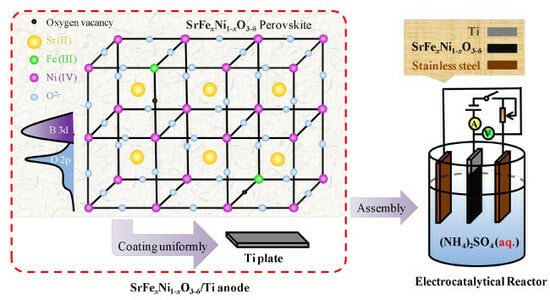
Nickel (Ni) has the outermost electron configuration of 3d84s2 with the abundant 3d electrons and empty 3d orbits among the transition metal elements (Mn: 3d54s2, Fe: 3d64s2, Co: 3d74s2 and Cu: 3d104s1) in the fourth period. Therefore, when Ni stands for the B-site element of ABO3, perovskite is expected to possess excellent electrocatalytic activity and appropriate conductivity. Moreover, in nickel-based perovskite of ABO3 (B = Ni), the strontium (Sr) element in the A-site can more strongly stabilize the cubic crystal construction of perovskite (t = 0.9704) compared with LaNiO3 (t = 0.9140), CaNiO3 (t = 0.9027) and BaNiO3 (t = 1.034) [19]. Oxygen vacancies in perovskite can provide more active sites and hydroxyl radicals (·OH) for electrocatalysis, significantly contributing to electron transfer during the reaction. In order to form more oxygen vacancies in SrNiO3 perovskite and then enhance its electrocatalytic properties, ferrum (Fe) can be doped and partially substitute the Ni element in the B-site, because they have similar electronegativity (Fe: 1.8, Ni: 1.8) and atomic radii (Fe: 124.1 pm, Ni: 124.6 pm). Moreover, Fe (III) and Ni (IV) show different valence states in favor of delivering electrons and forming oxygen vacancies according to the electroneutrality principle [20]. Therefore, based on the above analysis, SrFexNi1−xO3−δ perovskites through doping Fe element into the SrNiO3 perform the better conductivity and electrocatalytic activity.
NH4+ represents a common contaminant in nitrogenous wastewater and the widely accepted mechanism for removing NH4+ in wastewater is the electrochemical oxidation during the electrocatalysis [21]. The ·OH can efficiently oxidize the NH4+ into N2 on the anode. Zhou et al. [22] degraded the ammonia nitrogen (NH4+-N) in wastewater by reverse electrodialysis (RED), and NH4+-N removal ratio reached 25% with the initial NH4+-N concentration of 10 mg L−1. Vlyssides et al. [23] treated the domestic wastewater (NH4+-N concentration of 150 mg L−1, pH = 6) through electrocatalysis and NH4+-N was reduced by 43.3% at the residence time of 30 min. In summary, the electrocatalytic method is expected to clean the wastewater containing NH4+.
In this paper, to improve the conductivity and electrocatalytic activity for removing NH4+ during the electrocatalysis, low-cost SrFexNi1−xO3−δ perovskites were fabricated by doping Fe into SrNiO3, and their optimum fabrication conditions were determined. Moreover, SrFexNi1−xO3−δ perovskites were coated on the Ti plate to prepare the SrFexNi1−xO3−δ/Ti electrodes and the electrocatalytic reactor (ECR) was assembled with the SrFexNi1−xO3−δ/Ti anode to clean simulated nitrogenous wastewater. Perovskite-type SrFexNi1−xO3−δ structure was testified and Fe was evidently doped into the SrNiO3 matrix. Herein, SrFexNi1−xO3−δ perovskites achieve attractive total nitrogen (TN) removal ratio and conductivity, indicating that they are suitable to clean nitrogenous wastewater in electrocatalysis.
2. Experimental
2.1. Materials and Reagents
N,N-dimethylacetamide (DMAc, AR grade, 99.5%), acetylene black (AR grade, 99.0%) and potassium bromide (KBr, AR grade, 99.0%) were provided by Tianjin Kemiou Chemical Reagent Co., Ltd. (Tianjin, China). Polyvinylidene fluoride (PVDF, 1015) was purchased from Solvay Co., Ltd. (Shanghai, China). Ammonium sulphate ((NH4)2SO4, AR grade, 99.0%), ferric nitrate (Fe(NO3)3·9H2O, AR grade, 99.5%), strontium nitrate (Sr(NO3)2, AR grade, 99.5%), nickel nitrate (Ni(NO3)3·6H2O, AR grade, 98.0%) and potassium persulfate (K2S2O8, AR grade, 99.5%) were supplied by Tianjin Yuanli Chemical Engineering Co., Ltd. (Tianjin, China). Sodium hydroxide (NaOH, AR grade, 99.0%) was obtained from Tianjin Guangfu Technology Development Co., Ltd. (Tianjin, China). Citric acid (C6H8O7·H2O, AR grade, 99.5%) was brought from Tianjin North Tianyi Chemicals Co., Ltd. (Tianjin, China). All reagents and chemicals were used as received.
2.2. Fabrication of the SrFexNi1−xO3−δ Perovskites
SrFexNi1−xO3−δ perovskites are fabricated using the citrate sol-gel method, which could be clearly observed from Figure 1 [24,25]. Firstly, stoichiometric amount of corresponding metal raw materials was determined, and the molar ratio of Sr: Ni: Fe: citric acid = 1: 1−x: x: 2.5, where x represented the doping content of Fe (x = 0, 0.1, 0.2, 0.3, 0.4 and 0.5). Then metal nitrates were fully dissolved in moderate deionized water to derive metallic ions aqueous solution. The mixture of both metallic ions, aqueous solution, and citric acid gently reacted at 80 °C for an appropriate time to form citrate complexation under magnetic stirring (rotational speed of 120 rpm), then dried (120 °C, 12 h) to evaporate the excess water in citrate sol-gel. Finally, precursors of SrFexNi1−xO3−δ were calcined in a muffle furnace through a temperature-programmed route, which was linearly heated to 300 °C and maintained for 1 h, then kept at high temperature (600–750 °C) for 2 h under an air atmosphere (heating rate of 5 °C min−1). The desired SrFexNi1−xO3−δ (x = 0, 0.1, 0.2, 0.3, 0.4 and 0.5) perovskites were obtained. In this work, the effect of reaction time for citrate sol-gel, calcination temperature, and doping content of Fe were discussed for fabricating SrFexNi1−xO3−δ perovskites.
2.3. Preparation of the SrFexNi1−xO3−δ/Ti Anode
Preparation of the SrFexNi1−xO3−δ/Ti anode is schematically displayed in Figure 2. Firstly, a titanium (Ti) plate (Grade TA2, 80.0 mm × 17.0 mm × 1.8 mm) was polished to remove the superficial oxide layer, degreased in hot detergent, and then etched by sharp blades to produce a rough grid surface, which served as the Ti substrate [26]. Afterward, anodic materials mentioned in Table 1 (SrFexNi1−xO3−δ perovskites, acetylene black, PVDF and DMAc in a mass ratio of 56:7:7:30) [27] were fully mixed into a viscous paste and uniformly coated on the Ti substrate with a spatula. Finally, the SrFexNi1−xO3−δ/Ti anode was prepared after being dried at 80 °C for 2 h.
2.4. Assembly of Electrocatalytic Reactor (ECR)
As shown in Figure 3, the ECR was a single compartment reactor (height of 120.0 mm, bottom diameter of 93.0 mm) and constructed with one anode and two cathodes: SrFexNi1−xO3−δ/Ti as the anode and stainless steels as the cathodes. All the electrodes were vertically fixed with a constant gap (20.0 mm) and both sides of Ti substrate (effective area of 5.10 cm2) were coated with the electrode materials. Simulated nitrogenous wastewater ((NH4)2SO4 solution, volume of 300 mL, initial TN concentration of 150 mg L−1) was intermittently poured into the ECR and forced to flow in turbulence by a magnetic stirrer (rotational speed of 120 rpm). ECR was powered just by a source of direct current (DC) connecting the amperemeter and slide rheostat with copper wires. Electrocatalytic current could be directly monitored from the amperemeter and the electrocatalytic current density was calculated by Equation (2). In addition, the electrocatalytic voltage was read by the digital multimeter between anode and cathode. The resistance, conductivity, and power density of ECR could be derived from Equations (3)–(5), respectively.
where I is the electrocatalytic current (A), U is the electrocatalytic voltage (V), S is the effective surface area of anode (cm2), L is the gap between anode and cathode (cm), r is the resistance of ECR (Ω), κ is the conductivity of ECR (mS cm−1), P is the electrocatalytic power density of ECR (mW cm−2), and i is the electrocatalytic current density of anode (mA cm−2). Current density mentioned in this paper referred to the electrocatalytic current density of anode and all the experimental results were measured at 25 ± 2 °C.
2.5. Measurement of Total Nitrogen (TN) Concentration
(NH4)2SO4 solution was selected as the simulated nitrogenous wastewater in various TN concentrations [28]. According to the discharge standard of pollutants for municipal wastewater treatment plant in China (GB 18918-2002, Class I-A Standard [29]), the TN concentrations before and after treatment by ECR were set as 150 mg/L and ≤ 15 mg/L, respectively. The TN concentration was determined by the alkaline potassium persulphate digestion UV spectrophotometric method (HJ 636-2012 [30]), whose details were provided in the Supplementary Information (Figure S1 and Table S1). The TN removal ratio was calculated by Equation (6):
where R is the TN removal ratio (%), C0 and C are the TN concentrations (mg L−1) of the nitrogenous wastewater before and after treatment, respectively.
2.6. Characterizations and Analysis Methods
2.6.1. Scanning Electron Microscope (SEM) and Energy Dispersive X-ray (EDX) Studies
Samples were sputtered with gold and their superficial morphologies were observed under the S4800 SEM (Hitachi, Tokyo, Japan) with a resolution of 1 nm. In addition, the relative content of elements in SrFexNi1−xO3−δ was analyzed by EDX system coupled with the SEM.
2.6.2. Fourier Transform Infrared (FT-IR) Studies
SrFexNi1−xO3−δ perovskite powders of 1 mg were dried, pressed into the pellets with KBr of 100 mg, and then preserved under vacuum. The FT-IR spectra of SrFexNi1−xO3−δ perovskite pellets were collected on an Avatar 370 spectrometer (Thermo Nicolet Corp., Billerica, GA, USA) with a wavelength coverage of 400–4000 cm−1 and a resolution of 0.1 cm−1.
2.6.3. Raman Analysis
The Raman spectra of SrFexNi1−xO3−δ materials were recorded using a high-resolution HR800 Raman spectrometer (Horiba, Montpellier, France) with a 532 nm laser beam as a light source. The laser was incident on the samples in a 2 μm diameter spot through a standard ×50 microscope objective lens and the accumulation time was 60 s for spectral measurement. The baseline of the Raman spectra was corrected with a silicon wafer.
2.6.4. X-Ray Diffraction (XRD) Studies
All the SrFexNi1−xO3−δ samples were tested on a Bruker D8 Advance diffractometer (Bruker, Karlsruhe, Germany) using Cu Kα (λ = 0.154184 nm) radiation source filtered by a Ni thin plate. The XRD data were collected over the range of 2θ = 10–80°.
2.6.5. Electrochemical Studies
Electrochemical studies were carried out in the Reference 3000 electrochemical workstation (Gamry, Warminster, America) equipped with a three-electrode system. SrFexNi1−xO3−δ materials of 1.8 mg were dispersed with ethanol of 2 mL and 0.5% Nafion of 0.05 mL under ultrasound, then the mixtures were dropped on the rotating disk electrode (RDE710, electrode area of 0.19625 cm2, rotating speed of 1000 rpm), which were dried and served as the working electrodes. The reference electrode and counter electrode were the saturated calomel electrode (SCE) and platinum wire, respectively. Electrochemical tests, including Electrochemical Impedance Spectroscopy (EIS) and Tafel curve, were studied in Na2SO4 (0.5 mol L−1) electrolyte solution under air atmosphere. The Tafel curve was performed with the sweep rate of 10 mV s−1 in a potential range from open potential to 0.6 V. EIS was performed with an amplitude of 5 mV from 100 kHz to 0.01 Hz. The relationship between current density and overpotential satisfies Equation (7), which can be applied and deduced into the low range of overpotential to calculate the value of exchange current density.
where η was the overpotential (mV) and i was the current density. When η = 0, the exchange current density (i0) could be deduced.
3. Results and Discussion
3.1. Optimum Fabrication Conditions of SrFexNi1−xO3−δ Materials
The appropriate conditions of ECR, namely the SrFexNi1−xO3−δ perovskites amount of 0.09804 g cm−2 coated on the anode, current density of 11.76 mA cm−2 and electrocatalytic time of 30 min, are determined in the Supplementary Information (Figures S2 and S3). Based on the above conditions of ECR, optimum fabrication conditions of SrFexNi1−xO3−δ perovskites (reaction time for citrate sol-gel, calcination temperature and doping content of Fe in SrFexNi1−xO3−δ) need to be further confirmed and their electrocatalytic properties are studied in cleaning the nitrogenous wastewater. Moreover, the chemical formulas and oxygen vacancy values (δ) of SrFexNi1−xO3−δ perovskites with different doping content values (x) can be determined by the electroneutrality.
3.1.1. Effect of Reaction Time for Citrate Sol-Gel on Electrocatalytic Properties of SrFexNi1−xO3−δ
During the fabrication of SrFexNi1−xO3−δ perovskites (calcination temperature of 700 °C), the effect of reaction time for citrate sol-gel on the electrocatalytic properties (TN removal ratio and conductivity of ECR) is illustrated in Figure 4. Obviously, TN removal ratio and the conductivity of ECR improve along with the reaction time for citrate sol-gel from 30–120 min, and then basically remain unchanged over 120 min. The results suggest the complexation between citric acid and metallic ions (Sr2+, Ni3+, and Fe3+) gradually increases in the citrate sol-gel, which is beneficial to fabricate the SrFexNi1−xO3−δ perovskites and promote their electrocatalytic properties within 120 min. Moreover, among the SrFexNi1−xO3−δ (x = 0, 0.1, 0.2, 0.3, 0.4 and 0.5) materials, SrFe0.3Ni0.7O2.85 achieves the superior TN removal ratio (56.20%) and conductivity of ECR (3.62 mS cm−1) at the reaction time of 120 min for citrate sol-gel. Thus, the optimum reaction time for citrate sol-gel is chosen as 120 min, over which the conductivity of ECR and the TN removal ratio have no obvious improvements.
3.1.2. The Effect of Calcination Temperature on the Electrocatalytic Properties of SrFexNi1−xO3−δ
In light of the reaction time of 120 min for the citrate sol-gel, the effect of calcination temperature on the electrocatalytic properties of SrFexNi1−xO3−δ clearly presents in Figure 5. With improving the calcination temperature for SrFexNi1−xO3−δ, both the conductivity of ECR and the TN removal ratio firstly increase and then drop, of which the peak values appear at 700 °C. This is because the SrFexNi1−xO3−δ materials gradually form and stabilize the perovskite-type structure when their calcination temperatures increase from 600–700 °C. However, in terms of SrFexNi1−xO3−δ materials, higher calcination temperatures (750 °C) probably destroy their crystal structure and framework [31]. Similarly, among the SrFexNi1−xO3−δ (x = 0, 0.1, 0.2, 0.3, 0.4 and 0.5) materials, SrFe0.3Ni0.7O2.85 achieves superior electrocatalytic activity (TN removal ratio of 56.20%) and ECR conductivity of 3.62 mS cm−1 at the calcination temperature of 700 °C. Thereby, the optimum calcination temperature for fabricating SrFexNi1−xO3−δ materials is considered as 700 °C.
3.1.3. The Effect of the Doping Content of Fe in SrFexNi1−xO3−δ on Electrocatalytic Properties
With regard to the optimum fabrication conditions (reaction time of 120 min for citrate sol-gel and a calcination temperature of 700 °C), the SrFexNi1−xO3−δ materials with different doping contents of Fe (x value) were coated on the anode in ECR, and their electrocatalytic properties were recorded in Table 2. The electrocatalytic voltage and power density of ECR with SrFexNi1−xO3−δ/Ti anode firstly drop and then ascend, raising the x. Additionally, both the TN removal ratio and conductivity of ECR give the inverse tendency plotted in Figure 6 that results from the increase of oxygen vacancies and the decline of t with the increase of x in SrFexNi1−xO3−δ perovskites. Among the SrFexNi1−xO3−δ (x = 0, 0.1, 0.2, 0.3, 0.4 and 0.5) materials, SrFe0.3Ni0.7O2.85 has the highest conductivity of ECR (3.62 mS cm−1) and TN removal ratio (56.20%), manifesting its superior conductivity and electrochemical activity. Therefore, the optimum doping content of Fe in SrFexNi1−xO3−δ is x = 0.3.
In the SrFexNi1−xO3−δ perovskites, electron exchange process of B-site elements takes place due to different ionic valence states between Fe (III) and Ni (IV), promoting the electronic and conductivity and the electron transmission capacity. Meanwhile, the Fe element has more empty 3d orbits (Fe: 3d64s2, four empty 3d orbits) and can be beneficial to deliver the electrons as compared with the Ni element (Ni: 3d84s2, two empty 3d orbits) in the B-site. With raising the x, low-valent substitution in the B-site increases the oxygen vacancies according to the electroneutrality, which can also improve the ionic conductivity and electrocatalytic reactivity of SrFexNi1−xO3−δ perovskites. However, the large x value relates to the low t value, which consequently leads to the oxygen octahedral distortion of perovskite owing to the Jahn-Teller effect, and the deviation from the standard cubic crystal structure conversely decreases the electrocatalytic reactivity and conductivity by doping [32,33].
The relationship of the x value in SrFexNi1−xO3−δ perovskite materials and their characteristic parameters (oxygen vacancy value (δ), tolerance factor (t), and 3d electron number in the B-site) is clearly shown in Figure 7. The increasing x value in SrFexNi1−xO3−δ naturally raises the oxygen vacancy value (δ) in accordance with the electroneutrality principle, which significantly avails to provide more electrocatalytic active sites and oxidative ·OH, as well as to enhance the conductivity in the perovskite. Oppositely, both the t value and 3d electron number in the B-site decreases with the x value in SrFexNi1−xO3−δ perovskite materials, limiting their electrocatalytic activity and conductivity. The t values of SrFexNi1−xO3−δ materials are totally over 0.92 (t = 0.9704–0.9296) and in the range of tolerance factor restriction (0.75 ≤ t ≤ 1.0), agreeing with the characteristic of the perovskite structure. From the results and analysis, the optimum x value in SrFexNi1−xO3−δ perovskites (x = 0.3) reveals the balance among oxygen vacancy, 3d electron number in the B-site, and the tolerance factor of the perovskite.
3.2. The Effect of Electrocatalytic Time on TN Concentration
In order to investigate the effect of electrocatalytic time and further decrease the TN concentration of wastewater to a lower level, ECR with the SrFe0.3Ni0.7O2.85/Ti anode (current density of 11.76 mA cm−2 and SrFexNi1−xO3−δ materials amount of 0.09804 g cm−2) is applied to treat the nitrogenous wastewater under the optimum conditions for fabricating SrFexNi1−xO3−δ materials (reaction time of 120 min for citrate sol-gel and calcination temperature of 700 °C). TN concentrations are measured at the corresponding electrocatalytic time, and their variation trend is shown in Figure 8. With the increase of electrocatalytic time, TN concentration of wastewater in ECR gradually declines and reaches below 15 mg L−1 at an electrocatalytic time of 150 min. At the same time, wastewater treated by ECR satisfies the discharge standard of pollutants for municipal wastewater treatment plants in China (GB 18918-2002 [29], Class I-A Standard, TN ≤ 15 mg L−1) with a TN removal ratio of 91.33% (from 150 mg L−1 to 14.62 mg L−1). In the range of low TN concentrations (15–60 mg L−1), the variation trend of the TN concentration with the electrocatalytic time is evidently slow, possibly contributing from the reduction of the concentration driving force for limiting the electrocatalytic efficiency. On the aspect of the wastewater quality standard, the appropriate electrocatalytic time can be chosen as 150 min, over which the nitrogenous wastewater treated by ECR meets the discharge standard of pollutants for municipal wastewater treatment plants in China (GB 18918-2002 [29], Class I-A Standard, TN ≤ 15 mg L−1). In conclusion, the optimum operating conditions and performance of ECR with SrFexNi1−xO3−δ/Ti anode are summarized in Table 3.
3.3. Characterization of SrFexNi1−xO3−δ
SrFexNi1−xO3−δ (x = 0, 0.1, 0.2, 0.3, 0.4 and 0.5) materials were fabricated under the optimum conditions (reaction time of 120 min for citrate sol-gel and calcination temperature of 700 °C). Then the corresponding SrFexNi1−xO3−δ materials were characterized as described below.
3.3.1. SEM Studies of SrFexNi1−xO3−δ and SrFexNi1−xO3−δ/Ti Anodes
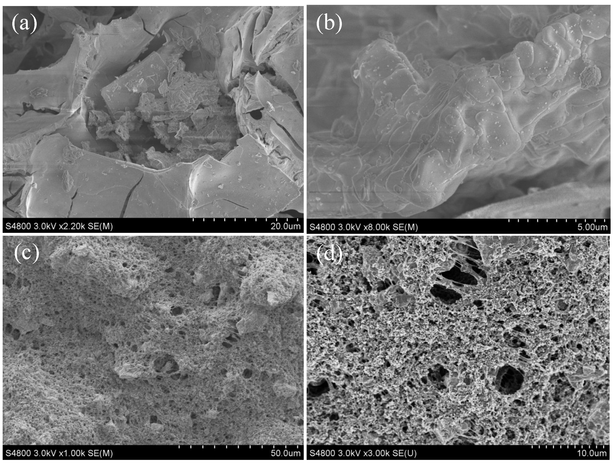
According to the optimum doping content of Fe (x = 0.3) for SrFexNi1−xO3−δ materials, SrFe0.3Ni0.7O2.85 has decent electrocatalytic properties. Furthermore, SrFe0.3Ni0.7O2.85 material and the anodic materials of the SrFe0.3Ni0.7O2.85/Ti anode are characterized through SEM and their surface morphologies are shown at different magnifications (Figure 9). SrFe0.3Ni0.7O2.85 material exhibits the blocky solid-solution shape (particle size of 10–100 μm) in Figure 9a,b, triggered by high calcination temperature and lasting calcination time during the fabrication process. In addition, the clear cracks of SrFe0.3Ni0.7O2.85 material can be also observed from Figure 9a. Moreover, Figure 9c,d show the adhesive phenomena and roughness on the coated surface of SrFe0.3Ni0.7O2.85/Ti anode, of which the loose morphology facilitates the mass transfer and the contact between contaminants and electrode surface.
3.3.2. FT-IR and Raman Analysis of SrFexNi1−xO3−δ
FT-IR spectra of perovskite-type SrNiO3 and SrNiO3 precursor were displayed in Figure 10. The SrNiO3 precursor was fabricated without the heat treatment and calcination process and the SrNiO3 perovskite was subsequently fabricated after heating and calcining the SrNiO3 precursor. In accordance with the literature [34,35], the wide and intensive absorption peak approximately ranging from 3000–3500 cm−1 can be assigned to the stretching vibration of O–H. Characteristic adsorption peaks at 640 cm−1, 895 cm−1, and 1074 cm−1 represent the C–H vibration. Meanwhile, the peaks of 1388 cm−1 and 1589 cm−1 belong to the stretching vibration of COO−, mainly contributing from the residual citric acid in the SrNiO3 precursor. Furthermore, the out-plane vibration of 812 cm−1 can be ascribed to nitrate radicals in the raw reagent.
As shown in Figure 11a, all the SrFexNi1−xO3−δ materials basically perform the same tendency in the FT-IR spectra. The low-frequency adsorption of 570 cm−1 possibly results from translational motion between the A-site cation and BO6 octahedron, suggesting the ionic vibration environment of the A-site element [36]. The intensive absorption band appearing at 735 cm−1 can be ascribed to the A-O-B stretching vibration and it is slightly split into two peaks in Fe-doped SrNiO3 due to the B-site difference of the ionic radius and the valence state [37]. The well-resolved peak of 858 cm−1 is considered to belong to the B–O stretching in perovskite compounds [38]. In addition, the vibrational peaks at the high-frequency region can be assigned to the asymmetric stretch (1450 cm−1, 2482 cm−1) and bend (1068 cm−1, 1770 cm−1) of the BO6 octahedra [39]. The absorption peak of Fe2O3 is not detected in the FT-IR spectroscopy, indicating that Fe element does center into the lattice of SrNiO3 perovskite. Moreover, the doping of the Fe element has not changed the perovskite framework structure, and its doping content (x) in SrFexNi1−xO3−δ can reach x = 0.5.
The Raman spectra of SrFexNi1−xO3−δ are exhibited in Figure 11b. The Raman active mode located around 143 cm−1 is associated with the vibration of the oxygen ion and A-site cation, reflecting the Raman information of Sr–O [40]. The mode appearing at 174 cm−1 is related to the bending vibration of oxygen and B-site cation, proving the occurrence of O–Ni–O and O–Fe–O in perovskite [41]. The Raman peak at 489 cm−1 is assigned to the breathing vibration of oxygen in (Ni/Fe)O6 octahedra, which is sensitive to the B-site substitution [42]. The Raman spectra can clearly identify the effect of B- and the A-site cations, which contributes to the perovskite structure of ABO3.
3.3.3. XRD Analysis of SrFexNi1−xO3−δ
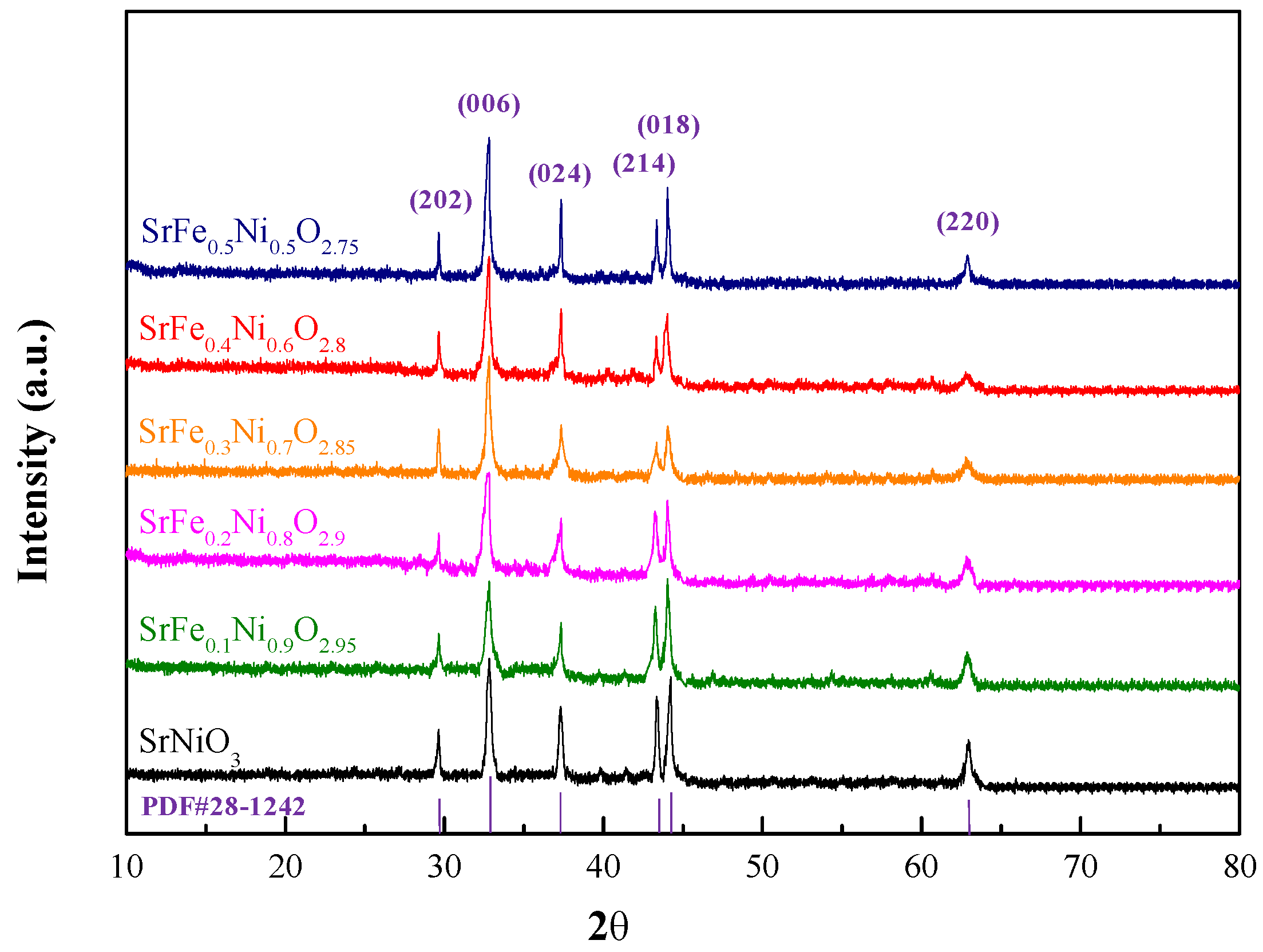
Further refined characterization of SrFexNi1−xO3−δ materials is conducted by XRD analysis in Figure 12. All the XRD diffraction peaks emerging at 29.6°, 32.8°, 37.3°, 44.1°, 43.4°, and 62.9° are sharp and intensive, certifying the brilliant crystallinity of SrFexNi1−xO3−δ materials. Above all, XRD patterns are featured with pure perovskite-type SrNiO3 (PDF#28-1242) and the doping of Fe element does not change the single perovskite phase [43,44], which agrees with the FT-IR and Raman analysis. No diffraction peaks of Fe2O3, Fe3O4, NiO, SrO or other impurities can be observed in the XRD patterns, demonstrating that Fe element is successfully doped into the crystal lattice of perovskite-type structure [45]. According to the results of analysis software (Jade 6.5), the average crystallite sizes are in the range of 432–485 nm for the SrFexNi1−xO3−δ materials. Moreover, the FWHM (full width at half maximum) value for the XRD patterns of SrFexNi1−xO3−δ materials is calculated as 0.332 at the sharpest XRD peak (2θ = 32.8°), which is located in the range (0.1–0.5) of the common crystal material (α-quartz, mica, corundum, diamond, et al.).
3.3.4. EDX Analysis of SrFexNi1−xO3−δ
Figure 13 shows the EDX spectrum of SrFe0.3Ni0.7O2.85 perovskite, in which the Sr, Ni, Fe, and O elements exist, confirming that the Fe element is present in the doped SrNiO3 perovskite. The C element and other impurity elements are not also found through the EDX analysis, suggesting that the citric acid is obviously decomposed during the heating and calcination process for fabricating the SrFe0.3Ni0.7O2.85 perovskite. Moreover, the relative content of elements in SrFe0.3Ni0.7O2.85 perovskite can be obtained in Table 4 and the molar ratio of Sr, Ni, Fe, and O elements in the tested material is about 1.00: 0.73: 0.34: 2.58, which is close to the theoretical molar ratio of SrFe0.3Ni0.7O2.85 perovskite.
3.3.5. Electrochemical Impedance Spectroscopy (EIS) and Tafel Curves Analysis of SrFexNi1−xO3−δ
The electrochemical results (EIS and Tafel curves) of SrFexNi1−xO3−δ perovskites present in Figure 14 and their electrochemical parameters (Rct and i0) are obtained in Table 5. As can be seen in Figure 14a, the high frequency-region of EIS presents apparent semicircle arcs, and the charge transfer resistance (Rct) of SrFexNi1−xO3−δ (x = 0, 0.1, 0.2, 0.3, 0.4 and 0.5) can be derived from the diameter of the semicircle. The Z’-axis intercepts reflect the solution resistance (Rs) basically fixed at 0.51 Ω cm2 and the oblique straight lines in low-frequency region represent the Warburg resistance (Zw) controlled by the electrode diffusion process. The Tafel curves of SrFexNi1−xO3−δ perovskites are shown in Figure 14b, and the asymmetric curves reflect the irreversible redox reaction on the SrFexNi1−xO3−δ perovskites. The i0 values of Tafel curves can be deduced from the intercepts when the overpotential (η) tends to zero, which relates to the electrocatalytic activity of SrFexNi1−xO3−δ perovskites. In Table 5, the SrFe0.3Ni0.7O2.85 perovskite performs the attractive electrocatalytic activity (i0 = 891.3 × 10⁻⁵ mA cm−2) and conductivity (lower Rct value of 7.58 Ω cm2) among the SrFexNi1−xO3−δ perovskites, which agrees with the electrocatalytic properties (TN removal ratio and conductivity of ECR) in cleaning the nitrogenous wastewater.
4. Conclusions
In this work, low-cost SrFexNi1−xO3−δ (x = 0, 0.1, 0.2, 0.3, 0.4 and 0.5) perovskites were fabricated using the citrate sol-gel method through doping Fe into the SrNiO3 matrix to improve the conductivity and electrocatalytic activity. In addition, the optimum conditions for fabricating SrFexNi1−xO3−δ perovskites (reaction time of 120 min for citrate sol-gel, a calcination temperature of 700 °C and Fe doping content of x = 0.3) were successively obtained. Then SrFexNi1−xO3−δ perovskites were coated on the Ti plate to prepare the SrFexNi1−xO3−δ/Ti electrode. The ECR was built with one SrFexNi1−xO3−δ/Ti anode and two stainless steel cathodes to clean nitrogenous wastewater. Furthermore, the characterization results strongly testify to the perovskite-type structure of SrFexNi1−xO3−δ. Finally, ECR with the SrFe0.3Ni0.7O2.85/Ti anode achieved the attractive TN removal ratio of 91.33% and conductivity of 3.62 mS cm−1 in the electrocatalytic process (electrocatalytic time of 150 min). In the optimum conditions, TN concentration in nitrogenous wastewater could be reduced below 15 mg L−1 and satisfied the discharge standard of pollutants for municipal wastewater treatment plants in China (GB 18918-2002, Class I-A Standard, TN ≤ 15 mg L−1). Therefore, the SrFexNi1−xO3−δ perovskites have a significant and fascinating application for cleaning nitrogenous wastewater.
Supplementary Materials
The following are available online at https://www.mdpi.com/1996-1944/12/3/511/s1, Figure S1: Standard work curve of TN concentration, Figure S2: Effect of amount of SrFexNi1−xO3−δ coated on the anode for the conductivity of ECR, Figure S3: Effect of amount of SrFexNi1−xO3−δ coated on the anode for TN removal ratio, Table S1: UV Absorbances of various TN concentrations for standard work curve.
Author Contributions
Conceptualization, Z.J.; Data curation, Z.J.; Formal analysis, Z.J.; Funding acquisition, Y.Z.; Investigation, L.C.; Methodology, J.W.; Supervision, Y.Z.; Writing—original draft, Z.J.; Writing—review & editing, Y.Z.
Funding
This study is funded by National Natural Science Foundation of China (No. 21676180, 21076143), by the key technologies R & D program of Tianjin (15ZCZDSF00160), by Tianjin Municipal Science and Technology Xinghai Program (No. KJXH2014-05).
Acknowledgments
This study is supported by the School of Chemical Engineering and Technology of Tianjin University.
Conflicts of Interest
The authors declare no conflict of interest. The funders had no role in the design of the study; in the collection, analyses, or interpretation of data; in the writing of the manuscript, and in the decision to publish the results.
References
- Camargo, J.A.; Alonso, A. Ecological and toxicological effects of inorganic nitrogen pollution in aquatic ecosystems: A global assessment. Environ. Int. 2006, 32, 831. [Google Scholar] [CrossRef] [PubMed]
- Bae, B.U.; Jung, Y.H.; Han, W.W.; Shin, H.S. Improved brine recycling during nitrate removal using ion exchange. Water Res. 2002, 36, 3330–3340. [Google Scholar] [CrossRef]
- Xia, G.; Xu, W.; Fang, Q.; Mou, Z.; Pan, Z. Graphene-modulated removal performance of nitrogen and phosphorus pollutants in a sequencing batch chlorella reactor. Materials 2018, 11, 2181. [Google Scholar] [CrossRef] [PubMed]
- Pressley, A.; Bishop, D.F.; Roan, S.G. Ammonia-nitrogen removal by breakpoint chlorination. Environ. Sci. Technol. 1972, 6, 622–628. [Google Scholar] [CrossRef]
- Akira, K.; Guanchen, L.; Michael, V.S.; Yoshihiro, K.; Koichi, K. Modeling the non-equilibrium process of the chemical adsorption of ammonia on gan(0001) reconstructed surfaces based on steepest-entropy-ascent quantum thermodynamics. Materials 2017, 10, 948. [Google Scholar] [CrossRef]
- Huo, S.; Chen, J.; Chen, X.; Wang, F.; Xu, L.; Zhu, F.; Guo, D.; Li, Z. Advanced treatment of the low concentration petrochemical wastewater by Tribonema sp microalgae grown in the open photobioreactors coupled with the traditional Anaerobic/Oxic process. Bioresour. Technol. 2018, 270, 476–481. [Google Scholar] [CrossRef] [PubMed]
- Cardoso, J.C.; Bessegato, G.G.; Zanoni, M.V.B. Efficiency comparison of ozonation, photolysis, photocatalysis and photoelectrocatalysis methods in real textile wastewater decolorization. Water Res. 2016, 98, 39–46. [Google Scholar] [CrossRef]
- Özcan, L.; Mutlu, T.; Yurdakal, S. Photoelectrocatalytic degradation of paraquat by Pt loaded TiO2 nanotubes on Ti anodes. Materials 2018, 11, 1715. [Google Scholar] [CrossRef]
- Okanishi, T.; Katayama, Y.; Muroyama, H.; Matsui, T.; Eguchi, K. SnO2-modified Pt electrocatalysts for ammonia-fueled anion exchange membrane fuel cells. Electrochim. Acta 2015, 173, 364–369. [Google Scholar] [CrossRef]
- Reyter, D.; Bélanger, D.; Roué, L. Nitrate removal by a paired electrolysis on copper and Ti/IrO2 coupled electrodes—influence of the anode/cathode surface area ratio. Water Res. 2010, 44, 1918–1926. [Google Scholar] [CrossRef]
- Pinhedo, L.; Pelegrini, R.; Bertazzoli, R.; Motheo, A.J. Photoelectrochemical degradation of humic acid on a (TiO2)0.7(RuO2)0.3 dimensionally stable anode. Appl. Catal. B 2005, 57, 75–81. [Google Scholar] [CrossRef]
- Wang, Y.; Cui, X.; Li, Y.; Chen, L.; Shu, Z.; Chen, H.; Shi, J. High surface area mesoporous LaFexCo1−xO3 oxides: Synthesis and electrocatalytic property for oxygen reduction. Dalton Trans. 2013, 42, 9448–9452. [Google Scholar] [CrossRef]
- Shawahni, A.M.; Abu-Jafar, M.S.; Jaradat, R.T.; Ouahrani, T.; Khenata, R.; Mousa, A.A.; Ilaiwi, K.F. Structural, elastic, electronic and optical properties of SrTMO3 (TM = Rh, Zr) compounds: Insights from FP-LAPW study. Materials 2018, 11, 2057. [Google Scholar] [CrossRef]
- Grabowska, E. Selected perovskite oxides: Characterization, preparation and photocatalytic properties—A review. Appl. Catal. B 2016, 186, 97–126. [Google Scholar] [CrossRef]
- Hwang, J.; Rao, R.R.; Giordano, L.; Katayama, Y.; Yu, Y.; Shao-Horn, Y. Perovskites in catalysis and electrocatalysis. Science 2017, 358, 751–756. [Google Scholar] [CrossRef]
- Shi, Z.; Guo, J.; Chen, Y.; Li, Q.; Pan, Y.; Zhang, H.; Xia, Y.; Huang, W. Lead-free organic-inorganic hybrid perovskites for photovoltaic applications: recent advances and perspectives. Adv. Mater. 2017, 29, 1–28. [Google Scholar] [CrossRef] [PubMed]
- Santos-García, A.J.D.; Solana-Madruga, E.; Ritter, C.; Ávila-Brande, D.; Fabeloc, O.; Sáez-Pucheb, R. Synthesis, structures and magnetic properties of the dimorphic Mn2CrSbO6 oxide. Dalton Trans. 2015, 44, 10665–10672. [Google Scholar] [CrossRef] [PubMed]
- Mori, D.; Oka, H.; Suzuki, Y.; Sonoyama, N.; Yamada, A.; Kanno, R.; Sumiya, Y.; Imanishi, N.; Takeda, Y. Synthesis, structure, and electrochemical properties of epitaxial perovskite La0.8Sr0.2CoO3 film on YSZ substrate. Solid State Ionics 2006, 177, 535–540. [Google Scholar] [CrossRef]
- Shannon, R.D. Revised effective ionic radii and systematic studies of interatomie distances in halides and chaleogenides. Acta Cryst. 2015, 32, 751–767. [Google Scholar] [CrossRef]
- Ascienzo, D.; Kurt, O.; Greenbaum, S.; Bayer, T.J.M.; Maier, R.A.; Randall, C.A.; Ren, Y. Formation of structural defects and strain in electrodegraded Fe-doped SrTiO3 crystals due to oxygen vacancy migration. J. Am. Ceram. Soc. 2018, 101, 2545–2561. [Google Scholar] [CrossRef]
- Yao, J.; Zhou, M.; Wen, D.; Xue, Q.; Wang, J. Electrochemical conversion of ammonia to nitrogen in non-chlorinated aqueous solution by controlling pH value. J. Electroanal. Chem. 2016, 776, 53–58. [Google Scholar] [CrossRef]
- Zhou, Y.; Zhao, K.; Hu, C.; Liu, H.; Wang, Y.; Qu, J. Electrochemical oxidation of ammonia accompanied with electricity generation based on reverse electrodialysis. Electrochim. Acta 2018, 269, 128–135. [Google Scholar] [CrossRef]
- Vlyssides, A.G.; Karlis, P.K.; Rori, N.; Zorpas, A.A. Electrochemical treatment in relation to pH of domestic wastewater using Ti/Pt electrodes. J. Hazard. Mater. 2002, B95, 215–226. [Google Scholar] [CrossRef]
- Oskoui, S.A.; Niaei, A.; Tseng, H.H.; Salari, D.; Izadkhah, B.; Hosseini, S.A. Modeling preparation condition and composition-activity relationship of perovskite-type LaxSr1−xFeyCo1−yO3 nano catalyst. ACS Comb. Sci. 2013, 15, 609–621. [Google Scholar] [CrossRef] [PubMed]
- Zhang, C.; Guo, Y.; Guo, Y.; Lu, G.; Boreave, A.; Retailleau, L.; Baylet, A.; Giroir-Fendler, A. LaMnO3 perovskite oxides prepared by different methods for catalytic oxidation of toluene. Appl. Catal. B 2014, 148–149, 490–498. [Google Scholar] [CrossRef]
- Xu, L.; Xin, Y.; Wang, J. A comparative study on IrO2-Ta2O5 coated titanium electrodes prepared with different methods. Electrochim. Acta 2009, 54, 1820–1825. [Google Scholar] [CrossRef]
- Wang, G.; Gao, J.; Fu, L.; Zhao, N.; Wu, Y.; Takamura, T. Preparation and characteristic of carbon-coated Li4Ti5O12 anode material. J. Power Sources 2007, 174, 1109–1112. [Google Scholar] [CrossRef]
- Vidal-Iglesias, F.J.; Garcia-Araez, N.; Montiel, V.; Feliu, J.M.; Aldaz, A. Selective electrocatalysis of ammonia oxidation on Pt (100) sites in alkaline medium. Electrochem. Commun. 2003, 5, 22–26. [Google Scholar] [CrossRef]
- China Standards Publication. Discharge Standard of Pollutants for Municipal Wastewater Treatment Plant in China; GB 18918-2002; China Standards Press: Beijing, China, 2002. [Google Scholar]
- China Standards Publication. Alkaline Potassium Persulphate Digestion UV Spectrophotometric Method; HJ 636-2012; China Standards Press: Beijing, China, 2012. [Google Scholar]
- Li, B.; Tang, C.; Wang, H.; Zhu, X.; Zhang, Q. An aqueous preoxidation method for monolithic perovskite electrocatalysts with enhanced water oxidation performance. Sci. Adv. 2016, 2, e1600495. [Google Scholar] [CrossRef]
- Hancock, C.A.; Slater, P.R. Synthesis of silicon doped SrMO3 (M = Mn, Co): stabilization of the cubic perovskite and enhancement in conductivity. Dalton Trans. 2011, 40, 5599–5603. [Google Scholar] [CrossRef]
- Tsuruta, A.; Nomura, K.; Mikami, M.; Kinemuchi, Y.; Terasaki, I.; Murayama, N.; Shin, W. Unusually small thermal expansion of ordered perovskite oxide CaCu3Ru4O12 with high conductivity. Materials 2018, 11, 1650. [Google Scholar] [CrossRef] [PubMed]
- Weng, S. Fourier Transform Infrared Spectroscopy; Chemical Industry Press: Beijing, China, 2010; pp. 377–389. [Google Scholar]
- Wu, T.; Xu, Z.; Zhang, Y.; Wang, H.; Cui, C.; Chang, B.; Feng, X.; Liu, W. A pH-responsive biodegradable high-strength hydrogel as potential gastric resident filler. Macromol. Mater. Eng. 2018, 303, 1800290. [Google Scholar] [CrossRef]
- Kim, Y.Y.; Dong, H.L.; Kwon, T.Y.; Park, S.H. Infrared spectra and seebeck coefficient of LnCoO3 with the perovskite structure. J. Solid State Chem. 1994, 112, 376–380. [Google Scholar] [CrossRef]
- Zhu, J.; Xiao, D.; Li, J.; Yang, X.; Wu, Y. Effect of Ce on NO direct decomposition in the absence/presence of O2 over La1−xCexSrNiO4 (0 ≤ x ≤ 0.3). J. Mol. Catal. A 2005, 234, 99–105. [Google Scholar] [CrossRef]
- Wang, H.; Li, G.; Li, L. Molten-salt-mediated synthesis and low-temperature electrical conduction of LnCoO3 (Ln = Pr, Nd, Sm, and Gd). J. Alloys Compd. 2014, 612, 227–232. [Google Scholar] [CrossRef]
- Ratheesh, R.; Sreemoolanadhan, H.; Sebastian, M.T. Vibrational analysis of Ba5−xSrxNb4O15 microwave dielectric ceramics resonators. J. Solid State Chem. 1997, 131, 2–8. [Google Scholar] [CrossRef]
- Ye, S.; Wang, C.; Jing, X. Photoluminescence and Raman spectra of double-perovskite Sr2Ca(Mo/W)O6 with A-and B-site substitutions of Eu3+. J. Electrochem. Soc. 2008, 155, J148–J151. [Google Scholar] [CrossRef]
- Fu, M.; Liu, X.; Chen, X. Raman spectra analysis for Ca(B’1/3B”2/3)O3-based complex perovskite ceramics. J. Appl. Phys. 2008, 104, 1182. [Google Scholar] [CrossRef]
- Caracas, R.; Cohen, R.E. Theoretical determination of the Raman spectra of MgSiO3 perovskite and post-perovskite at high pressure. Geophys. Res. Lett. 2006, 33, 229–237. [Google Scholar] [CrossRef]
- Ksepko, E. Perovskite-type Sr(Mn1−xNix)O3 materials and their chemical-looping oxygen transfer properties. Int. J. Hydrogen Energy 2014, 39, 8126–8137. [Google Scholar] [CrossRef]
- Zinkevich, M. Constitution of the Sr-Ni-O system. J. Solid State Chem. 2005, 178, 2818–2824. [Google Scholar] [CrossRef]
- Sun, Z.; Yuan, H.; Liu, Z.; Han, B.; Zhang, X. A highly efficient chemical sensor material for H2S: α-Fe2O3 nanotubes fabricated using carbon nanotube templates. Adv. Mater. 2005, 17, 2993–2997. [Google Scholar] [CrossRef]
Figure 1.
Schematic diagram of the fabrication process of the SrFexNi1−xO3−δ perovskites.

Figure 2.
Schematic diagram of the preparation of the SrFexNi1−xO3−δ/Ti anode. (N,N-dimethylacetamide, DMAc; Polyvinylidene fluoride, PVDF)
Figure 2.
Schematic diagram of the preparation of the SrFexNi1−xO3−δ/Ti anode. (N,N-dimethylacetamide, DMAc; Polyvinylidene fluoride, PVDF)

Figure 3.
Schematic diagram of the electrocatalytic reactor (ECR).

Figure 4.
The effect of reaction time for citrate sol-gel on the electrocatalytic properties of SrFexNi1−xO3−δ.
Figure 4.
The effect of reaction time for citrate sol-gel on the electrocatalytic properties of SrFexNi1−xO3−δ.

Figure 5.
The effect of calcination temperature on the electrocatalytic properties of SrFexNi1−xO3−δ.
Figure 5.
The effect of calcination temperature on the electrocatalytic properties of SrFexNi1−xO3−δ.

Figure 6.
The effect of Fe doping content (x value) in SrFexNi1−xO3−δ on the electrocatalytic properties.
Figure 6.
The effect of Fe doping content (x value) in SrFexNi1−xO3−δ on the electrocatalytic properties.

Figure 7.
Characteristic parameters of SrFexNi1−xO3−δ perovskites: Oxygen vacancy value (δ), tolerance factor (t), and 3d electron number in the B-site.
Figure 7.
Characteristic parameters of SrFexNi1−xO3−δ perovskites: Oxygen vacancy value (δ), tolerance factor (t), and 3d electron number in the B-site.

Figure 8.
The effect of electrocatalytic time on TN concentration.

Figure 9.
SEM images of (a,b) SrFe0.3Ni0.7O2.85 and (c,d) the surface of SrFe0.3Ni0.7O2.85/Ti anode.
Figure 9.
SEM images of (a,b) SrFe0.3Ni0.7O2.85 and (c,d) the surface of SrFe0.3Ni0.7O2.85/Ti anode.

Figure 10.
FT-IR spectra of SrNiO3 perovskite and SrNiO3 precursor.

Figure 11.
FT-IR (a) and Raman (b) spectra of SrFexNi1−xO3−δ.

Figure 12.
XRD patterns of SrFexNi1−xO3−δ.

Figure 13.
EDX spectrum of SrFe0.3Ni0.7O2.85 perovskite.

Figure 14.
Electrochemical Impedance Spectroscopy (EIS) (a) and Tafel curves (b) of SrFexNi1−xO3−δ.


Table 1.
Components of materials for preparing the SrFexNi1−xO3−δ/Ti anode.
| Anodic Materials | Mass Ratio (wt.%) | Function and Characteristic |
|---|---|---|
| SrFexNi1−xO3−δ perovskites | 56 | Active material: stability, attractive electrochemical activity |
| Acetylene black | 7 | Conductor: huge specific surface area |
| Polyvinylidene fluoride (PVDF) | 7 | Binder: antioxidation, hydrophobicity |
| N,N-dimethylacetamide (DMAc) | 30 | Solvent: volatility, low toxicity |
Table 2.
The effect of different anodes in ECR for cleaning nitrogenous wastewater.
| SrFexNi1−xO3−δ Coated on the Anode | Voltage (V) | Power Density (mW cm−2) | Conductivity of ECR (mS cm−1) | TN Removal Ratio (%) |
|---|---|---|---|---|
| SrNiO3 | 6.97 | 82.0 | 3.38 | 37.21 |
| SrFe0.1Ni0.9O2.95 | 6.68 | 78.6 | 3.52 | 49.75 |
| SrFe0.2Ni0.8 O2.9 | 6.54 | 76.9 | 3.60 | 54.41 |
| SrFe0.3Ni0.7O2.85 | 6.50 | 76.4 | 3.62 | 56.20 |
| SrFe0.4Ni0.6O2.8 | 6.72 | 79.1 | 3.50 | 47.60 |
| SrFe0.5Ni0.5O2.75 | 6.85 | 80.6 | 3.43 | 42.23 |
Total nitrogen (TN); Electrocatalytic Reactor (ECR).
Table 3.
The optimum operation conditions and performance of ECR with the SrFexNi1−xO3−δ/Ti anode.
| Item | Value |
|---|---|
| Anode | SrFexNi1−xO3−δ/Ti, 80.0 mm × 17.0 mm × 1.8 mm |
| Cathode | Stainless steel, 50.0 mm × 20.0 mm × 1.0 mm |
| Electrode gap | 20.0 mm |
| Effective surface area of anode | 5.10 cm2 |
| Perovskite amount coated on the anode | 0.09804 g cm−2 |
| Electrocatalytic current identity | 11.76 mA cm−2 |
| Perovskite material for the anode of ECR | SrFe0.3Ni0.7O2.85 |
| Reaction time for citrate sol-gel | 120 min |
| Calcination temperature for SrFexNi1−xO3−δ | 700 °C |
| Conductivity | 3.62 mS cm−1 |
| Initial TN concentration in wastewater | 150 mg L−1 |
| TN removal ratio | 91.33% |
| Treatment time | 150 min |
| Treatment volume | 300 mL |
Table 4.
The relative content of elements in SrFe0.3Ni0.7O2.85 perovskite.
| Elements | Weight Percent (%) | Atom Percent (%) |
|---|---|---|
| Sr | 46.02 | 21.53 |
| Ni | 22.44 | 15.67 |
| Fe | 9.85 | 7.23 |
| O | 21.69 | 55.57 |
| Total | 100.00 | 100.00 |
Table 5.
Parameters of SrFexNi1−xO3−δ perovskites.
| SrFexNi1−xO3−δ Perovskites | Rct (Ω cm2) | i0 (mA cm−2) |
|---|---|---|
| SrNiO3 | 17.88 | 2.570 × 10⁻⁵ |
| SrFe0.1Ni0.9O2.95 | 11.54 | 54.95 × 10⁻⁵ |
| SrFe0.2Ni0.8O2.9 | 9.97 | 158.5 × 10⁻⁵ |
| SrFe0.3Ni0.7O2.85 | 7.58 | 891.3 × 10⁻⁵ |
| SrFe0.4Ni0.6O2.8 | 13.85 | 37.15 × 10⁻⁵ |
| SrFe0.5Ni0.5O2.75 | 15.88 | 12.02 × 10⁻⁵ |
© 2019 by the authors. Licensee MDPI, Basel, Switzerland. This article is an open access article distributed under the terms and conditions of the Creative Commons Attribution (CC BY) license (http://creativecommons.org/licenses/by/4.0/).
Share and Cite
MDPI and ACS Style
Zhang, Y.; Jin, Z.; Chen, L.; Wang, J. RETRACTED: SrFexNi1−xO3−δ Perovskites Coated on Ti Anodes and Their Electrocatalytic Properties for Cleaning Nitrogenous Wastewater. Materials 2019, 12, 511. https://doi.org/10.3390/ma12030511
AMA Style
Zhang Y, Jin Z, Chen L, Wang J. RETRACTED: SrFexNi1−xO3−δ Perovskites Coated on Ti Anodes and Their Electrocatalytic Properties for Cleaning Nitrogenous Wastewater. Materials. 2019; 12(3):511. https://doi.org/10.3390/ma12030511
Chicago/Turabian StyleZhang, Yuqing, Zilu Jin, Lijun Chen, and Jiaqi Wang. 2019. "RETRACTED: SrFexNi1−xO3−δ Perovskites Coated on Ti Anodes and Their Electrocatalytic Properties for Cleaning Nitrogenous Wastewater" Materials 12, no. 3: 511. https://doi.org/10.3390/ma12030511
Note that from the first issue of 2016, this journal uses article numbers instead of page numbers. See further details here.