Article

Molecular Dynamics Study on Mechanical Properties of Interface between Urea-Formaldehyde Resin and Calcium-Silicate-Hydrates

1
Guangdong Provincial Key Laboratory of Durability for Marine Civil Engineering, College of Civil and Transportation Engineering, Shenzhen University, Shenzhen 518060, China
2
School of Science, Harbin Institute of Technology, Shenzhen 518055, China
*
Authors to whom correspondence should be addressed.
Materials 2020, 13(18), 4054; https://doi.org/10.3390/ma13184054
Submission received: 28 July 2020 / Revised: 29 August 2020 / Accepted: 8 September 2020 / Published: 12 September 2020
(This article belongs to the Special Issue Molecular Dynamics in Nanomaterials and Nanofluids)

Abstract

:
Microcapsule based self-healing concrete can automatically repair damage and improve the durability of concrete structures, the performance of which depends on the binding behavior between the microcapsule wall and cement matrix. However, conventional experimental methods could not provide detailed information on a microscopic level. In this paper, through molecular dynamics simulation, three composite models of Tobermorite (Tobermorite 9 Å, Tobermorite 11 Å, Tobermorite 14 Å), a mineral similar to Calcium-Silicate–Hydrate (C–S–H) gel, with the linear urea–formaldehyde (UF), the shell of the microcapsule, were established to investigate the mechanical properties and interface binding behaviour of the Tobermorite/UF composite. The results showed that the Young’s modulus, shear modulus and bulk modulus of Tobermorite/UF were lower than that of ‘pure’ Tobermorite, whereas the tensile strength and failure strain of Tobermorite/UF were higher than that of ‘pure’ Tobermorite. Moreover, through radial distribution function (RDF) analysis, the connection between Tobermorite and UF found a strong interaction between Ca, N, and O, whereas Si from Tobermorite and N from UF did not contribute to the interface binding strength. Finally, high binding energy between the Tobermorite and UF was observed. The research results should provide insights into the interface behavior between the microcapsule wall and the cement matrix.

1. Introduction

The micro-cracks generated within concrete can seriously impact the performance and durability of concrete, leading to the short service life of concrete [1,2]. In recent decades, to improve the durability of concrete, many researchers have attempted to apply different technologies to prevent and repair the cracks [3,4,5]. According to the bionics principle, an advanced self-healing technology incorporating the remediation/repair agent into concrete has been developed, which can automatically locate and repair the micro-cracks and imply the self-remediation and regeneration function [6]. When the crack occurs, the repair agent embedded in the cementitious matrix can be triggered due to the change in environment, such as force, heat or chemicals, which then release the healing agent, i.e., epoxy, to cement the crack surface and delay the propagation of the cracks to achieve the self-healing target [7]. Compared to passive repair work, self-healing technology has many advantages, such as low cost, sensitive response, and accurate repair [8,9]. Among the different type of self-healing system, microcapsule-based self-healing concrete has been proven to be a good method for repairing the concrete cracks [10].
Microencapsulation is a technology for preparing core-shell structured microcapsules with a repair agent core and polymeric shell, which has been widely employed in the pharmaceutical, food and printing industries [11]. In the construction industry, the incorporation of microcapsules in concrete has been demonstrated to play an obvious and positive role for the maintenance of the mechanical properties of concrete by repairing micro-cracks [12]. This is particularly true in the case of epoxy/urea-formaldehyde (UF) microcapsules, which have attracted increased attention from both scientists and engineers [13]. In general, when the micro-cracks occur in the matrix, under the force from the tip, the UF shell of microcapsules is ruptured to release a healing agent to prevent the extension of internal micro-cracks in the structure [9]. Therefore, the addition of microcapsules in concrete could not only accurately locate the defects within the cementitious matrix, but also repair the micro-cracks [14]. To ensure the implementation of the self-healing function, it has to provide sufficient strength, so that the microcapsules should remain intact during mixing, and have the ability to be ruptured under external force when the micro-cracks occur [15]. Thus, a high adhesion strength between the microcapsule wall and the cementitious matrix is required [15,16]. Therefore, the interface properties between the shell of microcapsules and the cementitious matrix are important to achieve the self-healing performance of a microcapsule-based system. However, when confined to the limitations of current techniques, it is difficult to experimentally investigate the interface property, particularly investigation at a microscopic level.
As it is a powerful tool, molecular dynamics (MD) simulation has been applied in cementitious materials on the molecular scale [17,18,19]. It is a kind of classical mechanical model based on molecules, which is often applied to study the structure and properties of molecular systems by solving Newton’s equations of motion. Therefore, it has been widely used in the chemical industry, biomedicine and other fields [20,21]. Since the calcium–silicate–hydrates (C–S–H) gel accounts for over 60% of the total hydration products of cement, which mainly contributes to the strength of hardened cement [22,23,24], the MD simulation has been used to study the C–S–H with different proposed C–S–H models [25,26,27,28], i.e., the colloidal gel-like structure [29], the incomplete lamellar mixture of Tobermorite and Jennite [30]. Ching et al. [31] analyzed the interface of the model of an explicitly solvated mixture of C–S–H and a silicon binding peptide, and found that a strong covalent bond was formed between the composite hybrid models. Rouhi and Atfi [32] studied the interactions between graphene-like monolayers and four different polymer chains, and found that increasing repeat units increased the interaction energy between polymer and nanosheet. Alkhateb et al. [33] established the model of C–S–H/graphene composite, and calculated the interface strength between the C–S–H and the graphene. Du et al. [34] established an interface model to study the adsorption energy of the interface between an epoxy resin/C–S–H in nanoscale and reported that the Ca2+ ions in C–S–H migrated to the interface and formed an electrostatic bond with the hydroxide in the resin, which is the main source of adsorption energy. All the studies mentioned above have proved the feasibility of MD simulation in characterizing the interface properties between the polymeric additives and cementitious matrix, which provides potential to apply the MD simulations in investigating the interface properties between the microcapsule and the cementitious matrix. Unfortunately, the MD simulation on investigating the interface property of the composite model of cement matrix and microcapsule wall (urea–formaldehyde resin), which is of great significance in revealing the trigger mechanism in the self-healing cementitious material, has not been systematically conducted yet.
The purpose of this study is, therefore, to study the binding behavior between the Tobermorite, a mineral with similar structure of C–S–H [35,36,37,38], and the linear UF, the shell of the microcapsule, via MD simulation. Four individual models of three different types of Tobermorite and one linear UF were first built. Then, three models of a Tobermorite/UF composite were established by combining these individual models. Then, the mechanical properties, including the modulus, atomic radial distribution function (RDF), stress–strain relationship and the binding energy, were obtained via MD by uniaxially stretching the entire structure along the z-direction.

2. Computational Methodology

2.1. Forcite

COMPASS is an ab initio forcefield inherited from CFF (consistent force fields), a previous generation of forcefield. It has been proven that the COMPASS exhibited a good consistency with the experiment data, which therefore, means the COMPASS is often employed in the calculation of cementitious material [39,40,41]. On the other hand, CVFF, a generalized force field, has been proven to be an appropriate tool to calculate the small organic crystals and meteorological structures for calculating the structure and binding energy, due to its advantage in reasonably predicting the vibration frequency and conformational energy [39]. Therefore, in this study, COMPASS was used for the calculation of Tobermorite, a similar structure of hydrated calcium silicate (C–S–H) gel, and CVFF was applied for the simulation of urea-formaldehyde resin as the microcapsule shell.

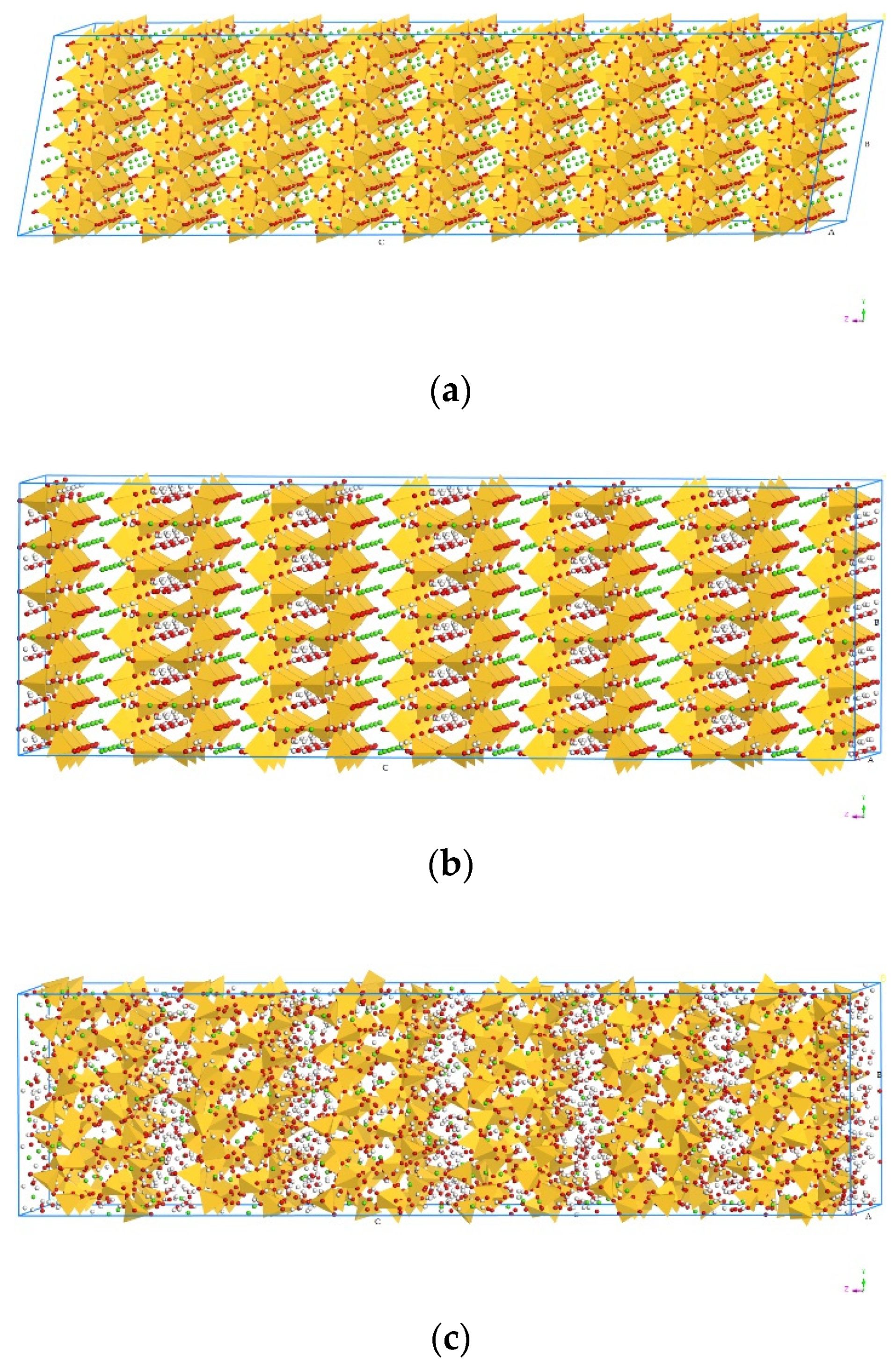
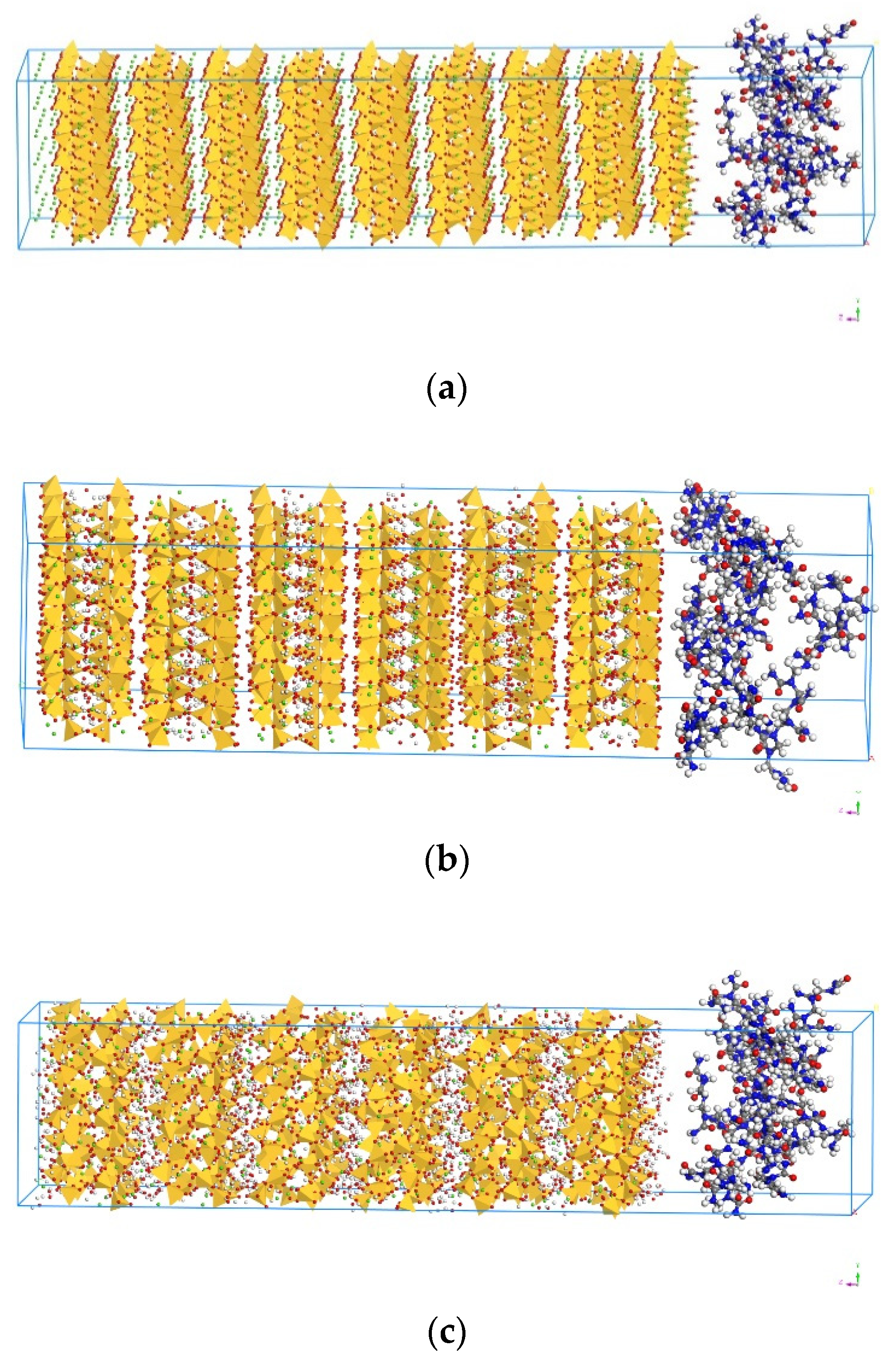
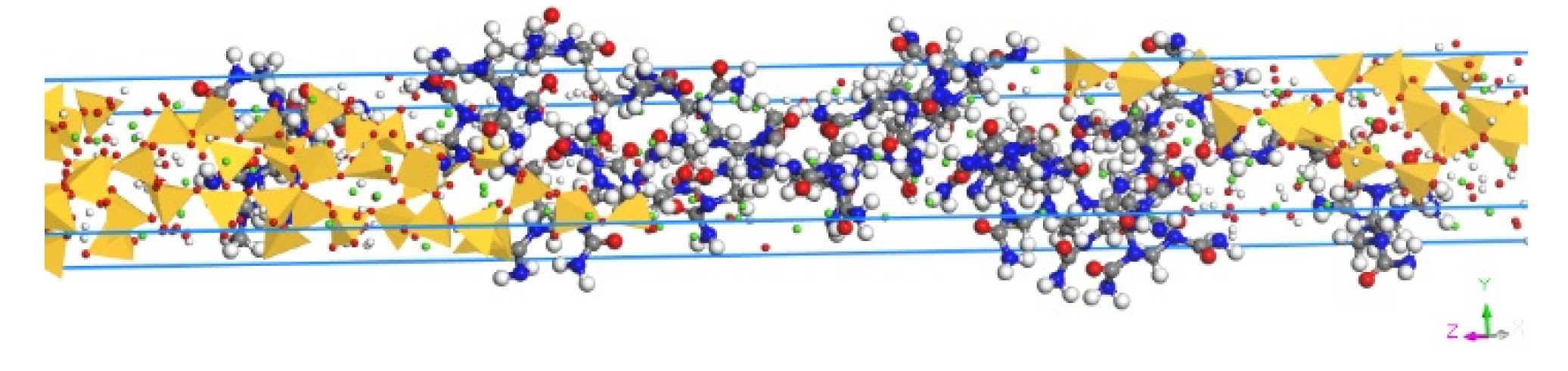
2.2. Model Construction

UF resin is a linear structure formed by the reaction of formaldehyde and urea under acidic conditions [42]. The chemical formula of UF resin is C2N2OH4n, and the monomer structure was built by following Xie’s approach (Figure 1), where the n value of the UF is usually in the range 7–10 [43]. In this study, to simplify the scenario, n = 7 was applied. Therefore, the UF chain composed of 7 repeating monomer units was built. Then, the amorphous cell of UF was constructed by an Amorphous Cell Construction. As shown in Figure 2, the amorphous cell of UF contained ten UF chains with a density of 1, and the cell lengths a and b will correspond with those of Tobermorite.
C–S–H has been identified as a layered structure consisting of a calcium layer linked to a silicate chain, which follows the pattern of Dreierkette with a repeated unit in every three tetrahedrons [44]. Therefore, the structure of C–S–H contains a linear silicate chain in the form of Dreierkette, with a number of positive calcium ions arranged in each layer and a negative silicon chain in the middle, and the space between each layer contains water molecules and calcium ions [45]. Due to its similar structure to C–S–H hydrates, models of the Tobermorite family, including Tobermorite 9 Å (T9, Ca5Si6O16(OH)2), Tobermorite 11 Å (T11, Ca4.5Si6O16(OH)·5H2O) and Tobermorite 14 Å (T14, Ca5Si6O16(OH)2·7H2O), have been established to simulate the C–S–H [46,47], where 9, 11, and 14 Å represent the distance of space between layers caused by different hydration degrees. In this study, to minimize the influence of model size in the calculation process, as shown in Figure 3, the original supercell models of T9, T11 and T14, were set as 3a × 3b × 6c, 2a × 3b × 2c, and 3a × 3b × 3c, respectively. Considering the errors that may appear in a small system, the total number of the molecules in the three models was controlled at around 5000, which ensured that the system was large enough to be accurately simulated [48,49]. Moreover, to establish the interphase between the Tobermorite and the UF, the C–S–H sheet were cleaved along the [0 0 1] direction (z-direction), and the XY plane was set to contact the UF. By using the Build Vacuum, the Vacuum thickness was set to 0, so as to change the model into a periodic structure.
For building a composite model of C–S–H and UF, as shown in Figure 4a–c, the supercell of the composite structure with two layers of C–S–H and UF was applied, where the UF was set as layer 1 and Tobermorite was set as layer 2 (applied for T9, T11 and T14). All the calculations were then conducted based on these three composites structures as T9-UF, T11-UF and T14-UF. The optimisation of the model in this paper can be viewed in the Supplementary Materials.

2.3. Molecular Dynamics Simulation

The MD simulation was conducted via Materials Studio. The Tobermorite model was energy-minimized, which was performed using a smart algorithm. Ewald summation method, a summation algorithm which can be used to calculate the coulombic interactions between ions in systems with periodic boundary conditions [50,51], was employed to calculate the non-bonded energy including both electrostatic and van der Waals interactions, where the cut-off distance in all simulations was set as 12 Å. Then, the layer was built by following the procedure described in Section 2.2. In order to optimize the structure of UF, the Tobermorite was firstly constrained and the energy minimization was performed again by using the CVFF forcefield. Then, the constraints of the Tobermorite were removed and the energy minimization was performed again to balance and optimize the entire structure by COMPASS forcefield.
Since the weakest part of the layered structure model was identified as the z-direction [23], the stress–strain behavior of the combined composites model of Tobermorite and UF was simulated under a uniaxial tensile on the z-direction. The entire simulation was performed under NPT (isothermal–isobaric ensemble, N is the number of atoms, P is the pressure, T is the temperature) integration conditions by following the procedures: (1) calculate 1ns after setting the temperature of 300 K and the external pressure as 0; (2) after the stresses in all directions were calmed down, the model was stretched in the z-direction by inputting the stress parameters. The step size was set to 1 fs. During the simulation, the x- and y-directions remained relaxed. In order to analyze the simulation results, the calculation results were saved every 10,000 steps.

3. Results and Discussions

3.1. Mechanical Property

The mechanical properties, including bulk modulus, shear modulus and elastic modulus from all x-, y- and z-directions, of the three composites models are shown in Table 1. It can be seen from the table that the bulk modulus of three models was in the range between 26 and 60 GPa, with the highest value obtained in T9-UF. Similarly, the highest shear modulus of 24 GPa was observed in T9-UF as well, whereas that of the other two models was below 10 GPa. Moreover, regardless of direction, the Young’s modulus simulated in this study was in the range of 3–36 GPa, which was smaller than that obtained from the reported experiment data, 15–45 GPa [52,53]. Since both cementitious materials and microcapsules are complex materials containing different components, the difference between the experiment and MD simulation could be due to simplification by the MD simulation. For example: (1) in the experiment, the microcapsule incorporated concrete is a type of anisotropic material, however, the simulated elastic model was calculated only in three directions (x-, y-, and z-); (2) the microcapsule, including both the urea–formaldehyde shell and epoxy core, was used in the experiment, however, only the UF shell of the microcapsule was simulated in this study; (3) in the experiment, the elastic modulus varied, incorporating different numbers of microcapsules, however, the content of UF shell in the simulation was fixed; (4) in the experiment, in addition to C–S–H, other hydration products, such as ettringite and portlandite, may also exist in the cementitious matrix, however, the simulation was only conducted with C–S–H, the main hydration products of cement.
Moreover, it can be noticed that, among the Young’s modulus in three directions, the largest value of Young’s modulus was observed in the y-direction, which is similar to the simulation of ‘pure’ Tobermorite [54]. This could be due to the fact that the silicate chain stands steady in the y-direction, while the hydrogen bonding network breaks in the other two directions.
Noticeably, the Young’s modulus, bulk modulus and shear modulus simulated by these three models were smaller than those simulated by the model of ‘pure’ Tobermorite [27], suggesting that the addition of the UF-based microcapsule reduced the overall mechanical properties of cementitious materials. Those simulation results showed a good agreement with the experimental investigation that the elastic modulus of the concrete was decreased after adding microcapsules [52]. At the microscopic level, the decreased elastic modulus could be due the larger distance among the atoms of the Tobermorite–UF model than that of the ‘pure’ Tobermorite, which results in the lower value of the binding force between the layers. Moreover, the decrease in elastic modulus indicated that the model exhibited a better ductility with the greater elastic deformation, which will be discussed in Section 3.3 below.

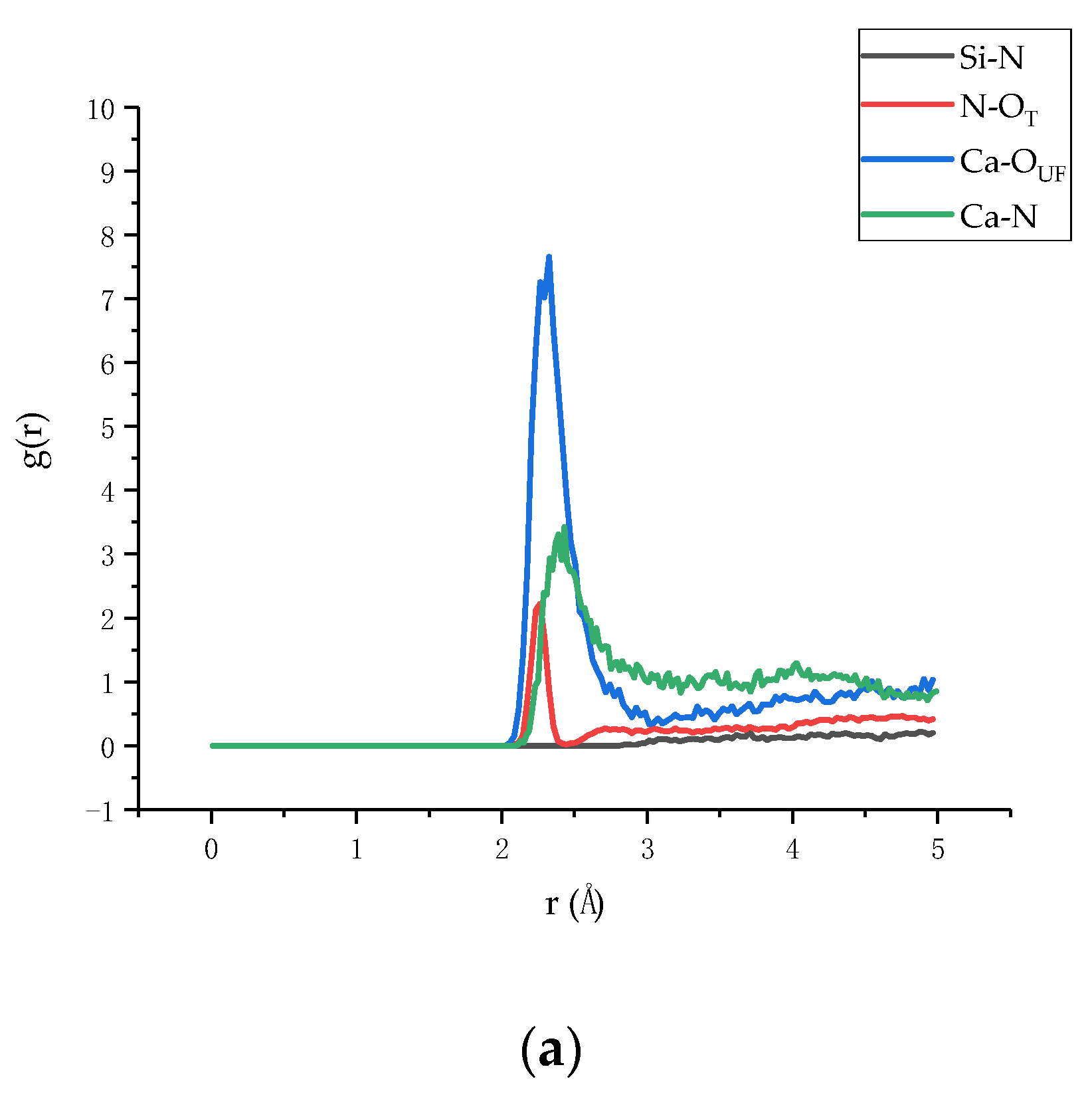
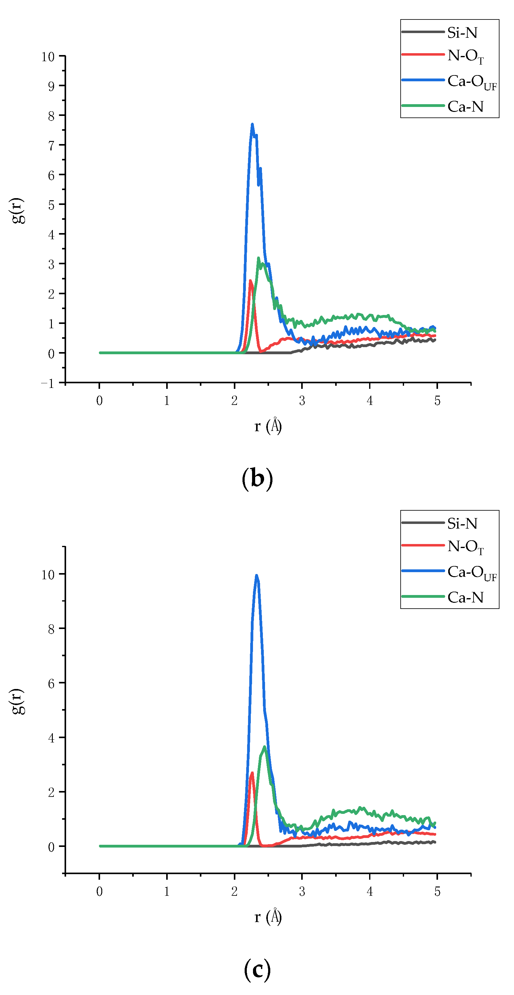
3.2. Radial Distribution Function

In order to understand the binding strength of the interface between the Tobermorite and the UF, the atomic radial distribution function (RDF), a method to characterize the composite surface adsorption points of the two materials was calculated for describing the spatial correlation between atoms [55,56]. The RDFs of three composites models, in terms of T9-UF, T11-UF, and T14-UF, are presented in Figure 5. As shown in the figure, in general, the RDFs of the three models exhibited the same trend, indicating that the modes of action of atoms in the three models were consistent. However, it can be seen from the figure that the RDF of Ca–N, N–OT and Ca–OUF was different to that of Si–N. A peak in the RDF appeared in Ca–N, N–OT, Ca–OUF, while no peaks belonging to Si–N were observed. Moreover, comparing the three composite models, the peaks in Ca–N of T9–UF, T11–UF, T14–UF were located at 2.39 Å, 2.33 Å, 2.45 Å, while the peaks of N–OT were at 2.27 Å, 2.24 Å, 2.27 Å, and Ca–OUF at 2.33 Å, 2.27 Å, 2.33 Å. According to previous studies, calcium ions may bind to oxygen atoms if the distance between the oxygen atoms and the calcium ions is less than 2.5 [57,58]. It can be seen from Figure 5a–c that the first peak in RDF of Ca–OUF in the three models was less than 2.5, and this result indicated the formation of a complex between UF and calcium ions (Figure 6).
The appeared sharp peaks indicated that the interface between the two materials was mainly due to the strong connection between Ca and N, N–OT and Ca–OUF, while Si and N showed no interactions. Therefore, it can be deduced that the most important interaction is the electrostatic interaction between the positive charge Ca and the negative charge O. The Ca2+ ion exhibits a bridging effect at the interface [55], which enhanced the electrostatic effect on the interface binding energy. Therefore, the simulation results indicated that Ca2+, O2− and N ions mainly play a bonding role at the interface.

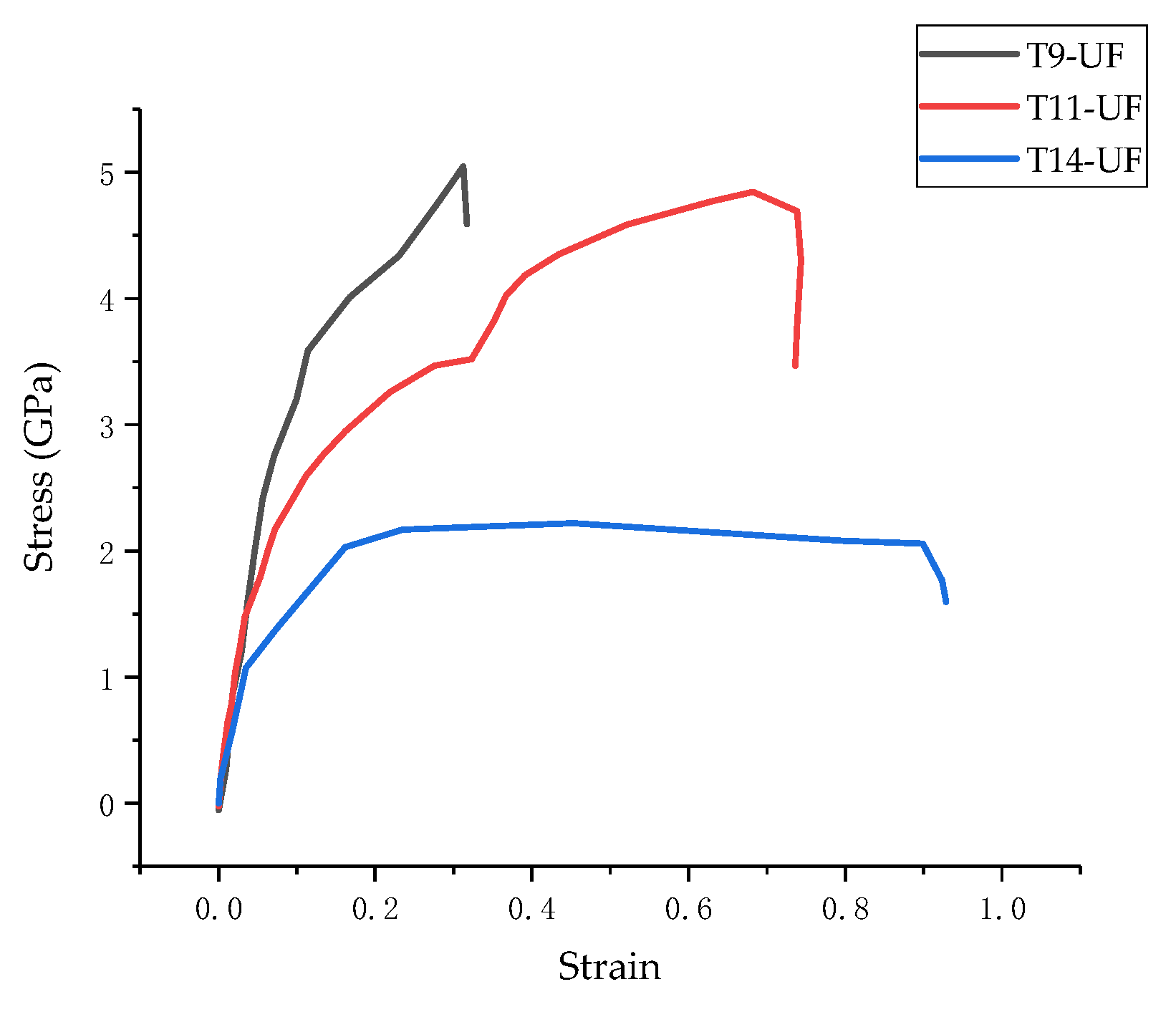
3.3. Stress–Strain Curve

The stress–strain curves of the three models in z-direction are plotted in Figure 7. It can be seen from the figure that there are three stages of stress variation in the tensile process: (1) the stress increases linearly in the elastic stage; (2) the stress increases slowly in the yield stage; (3) the stress reduces in the failure stage. Moreover, based on the stress–strain curve, the tensile strengths of the three composites models of T9-UF, T11-UF and T14-UF, were 5.05, 4.84 and 2.22 GPa, respectively. Clearly, the strength of T14-UF was obviously smaller than that of the other two models. This could be because the layer spacing of T14-UF model was larger than that of the other two models, which therefore showed a weak connection between intermediate water and Ca2+ ion. Compared with the results generated from the model of pure Tobermorite, which were reported as 0.87, 0.93 and 1.01 GPa in the literature [23], the simulated strengths of the three composite models were larger, which indicated that the tensile strength in the z-direction increased when the UF microcapsule was added. The results were similar to the finding with the addition of graphene in cementitious matrix [59]. The increased tensile strength in the Tobermorite–UF model can be explained by the strong binding strength between Tobermorite and UF. As reported in Section 3.2, the Ca, O in Tobermorite and N and O in UF exhibited strong connection, which ensured a stronger connection between the UF and the Tobermorite. Therefore, when the model was uniaxially stretched in the z-direction, UF was effectively connected to Tobermorite. As shown in Figure 8, when Tobermorite fractures between layers (the left and right side of the UF) occurred, the UF can reduce the crack propagation, and thus increase the strength of the model.
Moreover, as shown in the Figure 7, the failure strains of the three models were 0.31, 0.68 and 0.45 respectively. Compared to the results from the model of ‘pure’ Tobermorite 11 Å of 0.2 [23], higher values were obtained in this study. This could due to the strong connection between Tobermorite and UF as proved in Section 3.2. When cracks began to appear between layers of Tobermorite, UF connected with the Tobermorite, thus delaying the propagation of cracks. Moreover, since UF is a chain structure, which can be expanded through stretching, compared to ‘pure’ Tobermorite, the entire composite model then becomes more malleable. The experiment shows that the ultimate strain of concrete was increased after adding UF-based microcapsules, which proved the feasibility of the results in this simulation [12]. The strain energy can be obtained by integrating the stress–strain curve by following the procedures proposed by Mohiuddin et al. [60]. According to the curves in Figure 7, the strain energies before the fracture of T9-UF, T11-UF and T14-UF were 1.09, 2.46 and 0.85 GPa, respectively. Unfortunately, the strain energy of ‘pure’ Tobermorite was missing, since it has been reported that higher elastic modulus results in a lower strain energy under the same stress [61]. As discussed in Section 3.1, the elastic modulus of Tobermorite–UF models was less than that of the ‘pure’ Tobermorite model. Therefore, it can be deducted that, under the same stress, the strain energy of the Tobermorite–UF model would be greater than that of ‘pure’ Tobermorite, and the ductility of the Tobermorite–UF model would be better than that of ‘pure’ Tobermorite.

3.4. Binding Energy

The binding strength of the interface between Tobermorite and UF can be evaluated by calculating the adhesion energy [62,63,64]. Therefore, in this study, the binding energy obtained as the opposite of the adhesion energy between the Tobermorite and the UF was calculated by following Equation (1) below [65]
E b = E I = [ E T o t a l ( E T + E U F )
where E b stands for the binding energy, E I stands for the interaction energy between the Tobermorite and the UF, E t o t a l for the total energy of the whole model, and E U F for the energy of the Tobermorite and UF.
The binding energy of three composite models is shown in Table 2. The binding energy of the three composite models was listed in the descending sequence of T9-UF, T11-UF and T14-UF. Moreover, as shown in the table, the binding energy of the T11-UF model was 2179 kcal/mol, which was similar to that of the T11- graphene oxide (GO) model (2338 kcal/mol) [66]. Since the greater the binding energy, the stronger the binding between the Tobermorite and the UF, the highest binding energy in T14-UF suggested that the easiest and closest interaction was obtained between T14 and the UF. As shown in Figure 5, the peak in the T14-UF model was higher and sharper than the other two models, which indicated a strong order and a tight relationship between atoms. This is consistent with the conclusion obtained here that the highest binding energy was observed in the T14-UF model. As discussed in Section 3.2, such a high binding energy between the Tobermorite and the UF could be mainly formed by the electrostatic interaction between Ca2+, O2− and N ions.
In sum, it can be indicated that Tobermorite can be connected with the UF shell, which can improve the strength of the composite. Moreover, the results suggested that the embedded microcapsule with the UF resin shell can attach to the hardened cementitious matrix, which cannot easily peel off and lose the self-healing performance.

4. Conclusions

In this paper, the mechanical properties and bonding behavior, including the interaction, binding energy and stress–strain curves, of three Tobermorite–UF resin composite models were studied by MD simulation to illustrate the performance of UF/Epoxy microcapsule in cementitious material. The results showed that there was a high binding energy between Tobermorite and UF, which was highly dependent on the strong interactions of Ca, N and O between Tobermorite and UF interfaces. The stress and strain curves by uniaxial tension of T9-UF, T11-UF and T14-UF revealed that the strength and failure strain of Tobermorite–UF were high, indicating a better ductility of the Tobermorite–UF models. The large binding energy between the Tobermorite and UF suggested a good compatibility of the UF/Epoxy microcapsule, which can be strongly adhered with the cementitious matrix. The results reveal the effectiveness of the microcapsule-based self-healing cementitious system.

Supplementary Materials

The following are available online at https://www.mdpi.com/1996-1944/13/18/4054/s1, Figure S1. The energy curve of the first step. Figure S2. The energy curve of the second step. Figure S3. The energy curve of the third step.

Author Contributions

X.W.: supervision, investigation, writing-revision. W.X.: investigation and writing—draft preparation. T.L.: methodology. J.R.: writing—revision. J.Z.: funding and conceptualization. N.H.: conceptualization. F.X.: funding and supervision. All authors have read and agreed to the published version of the manuscript.

Funding

This research was financially supported by the financial support provided by the Key-Area Research and Development Program of Guangdong Province (2019B111107002), the General Program of the National Natural Science Foundation of China (51978409).

Conflicts of Interest

The authors declare that the research was conducted in the absence of any commercial or financial relationships that could be construed as a potential conflict of interest.

References

  1. Beushausen, H.; Bester, N. The influence of curing on restrained shrinkage cracking of bonded concrete overlays. Cement Concr. Res. 2016, 87, 87–96. [Google Scholar] [CrossRef]
  2. Li, W.; Dong, B.; Yang, Z.; Xu, J.; Chen, Q.; Li, H.; Xing, F.; Jiang, Z. Recent Advances in Intrinsic Self-Healing Cementitious Materials. Adv. Mater. 2018, 30, 1705679. [Google Scholar] [CrossRef]
  3. Ryu, J.S.; Otsuki, N. Crack closure of reinforced concrete by electrodeposition technique. Cement Concr. Res. 2002, 32, 159–164. [Google Scholar] [CrossRef]
  4. Banthia, N.; Gupta, R. Influence of polypropylene fiber geometry on plastic shrinkage cracking in concrete. Cement Concr. Res. 2006, 36, 1263–1267. [Google Scholar] [CrossRef]
  5. Ray, I.; Gong, Z.; Davalos, J.F.; Kar, A. Shrinkage and cracking studies of high performance concrete for bridge decks. Constr. Build. Mater. 2012, 28, 244–254. [Google Scholar] [CrossRef]
  6. Han, N.; Xing, F. A Comprehensive Review of the Study and Development of Microcapsule Based Self-Resilience Systems for Concrete Structures at Shenzhen University. Materials 2016, 10, 2. [Google Scholar] [CrossRef]
  7. Dong, B.; Han, N.; Zhang, M.; Wang, X.; Cui, H.; Xing, F. A microcapsule technology based self-healing system for concrete structures. J. Earthq. Tsunami 2013, 7, 1350014. [Google Scholar] [CrossRef]
  8. Tang, W.; Kardani, O.; Cui, H. Robust evaluation of self-healing efficiency in cementitious materials—A review. Constr. Build. Mater. 2015, 81, 233–247. [Google Scholar] [CrossRef]
  9. Tittelboom, K.V.; Belie, N.D. Self-Healing in Cementitious Materials—A Review. Materials 2013, 6, 2182–2217. [Google Scholar] [CrossRef] [Green Version]
  10. Wang, X.; Sun, P.; Han, N.; Xing, F. Experimental Study on Mechanical Properties and Porosity of Organic Microcapsules Based Self-Healing Cementitious Composite. Materials 2017, 10, 20. [Google Scholar] [CrossRef] [Green Version]
  11. Brown, E.N.; Kessler, M.R.; Sottos, N.R.; White, S.R. In situ poly(urea-formaldehyde) microencapsulation of dicyclopentadiene. J. Microencapsul. 2003, 20, 719–730. [Google Scholar] [CrossRef] [PubMed] [Green Version]
  12. Han, T.; Wang, X.; Li, D.; Li, D.; Xing, F.; Ren, J.; Han, N. Stress-strain behaviour and pore structure of microcapsule-based self-healing cementitious composite under triaxial tests. Constr. Build. Mater. 2020, 241, 118009. [Google Scholar] [CrossRef]
  13. Zhang, M.; Xing, F.; Shi, K.Y.; Du, X.X. Study on Organic Microcapsule Based Self-Healing Cementitious Composite. Adv. Mater. Res. 2011, 239–242, 764–767. [Google Scholar] [CrossRef]
  14. Bekas, D.G.; Tsirka, K.; Baltzis, D.; Paipetis, A.S. Self-healing materials: A review of advances in materials, evaluation, characterization and monitoring techniques. Compos. Part B 2016, 87, 92–119. [Google Scholar] [CrossRef]
  15. Zhang, M. A Study on Microcapsule Based Self-Healing Method and Mechanism for Cementitious Composites. Ph.D. Thesis, Central South University, Changsha, China, 2013. [Google Scholar]
  16. Li, V.C.; Lim, Y.M.; Chan, Y.-W. Feasibility study of a passive smart self-healing cementitious composite. Compos. Part B 1998, 29, 819–827. [Google Scholar] [CrossRef]
  17. Wu, W.; Al-Ostaz, A.; Cheng, A.H.-D.; Song, R.C. Concrete as a hierarchical structural composite material. Int. J. Multiscale Comput. Eng. 2010, 8, 585–595. [Google Scholar] [CrossRef]
  18. Lin, F.; Christian, M. Micromechanics model for the effective elastic properties of hardened cement pastes. Acta Mater. Compos. Sin. 2007, 24, 184–189. [Google Scholar]
  19. Haecker, C.J.; Garboczi, E.J.; Bullard, J.W.; Bohn, R.B.; Sun, Z.; Shah, S.P.; Voigt, T. Modeling the linear elastic properties of Portland cement paste. Cement Concr. Res. 2005, 35, 1948–1960. [Google Scholar] [CrossRef]
  20. Liu, J.; Zhang, L.; Cao, D.; Shen, J.; Gao, Y. Computational simulation of elastomer nanocomposites: Current progress and future challenges. Rubber Chem. Technol. 2012, 85, 450–481. [Google Scholar] [CrossRef]
  21. Qianrui, Z.; Yong, H.; Leichao, W.; Measurement, T. Influence of electrostatic field on the adsorption of phenol on single-walled carbon nanotubes: A study by molecular dynamics simulation. Chem. Eng. J. 2019, 363, 278–284. [Google Scholar]
  22. Macphee, D.E.; Folli, A. Photocatalytic concretes—The interface between photocatalysis and cement chemistry. Cement Concr. Res. 2016, 85, 48–54. [Google Scholar] [CrossRef]
  23. Hou, D.; Zhu, Y.; Lu, Y.; Li, Z. Mechanical properties of calcium silicate hydrate (C–S–H) at nano-scale: A molecular dynamics study. Mater. Chem. Phys. 2014, 146, 503–511. [Google Scholar] [CrossRef]
  24. Qomi, M.A.; Krakowiak, K.J.; Bauchy, M.; Stewart, K.L.; Shahsavari, R.; Jagannathan, D.; Brommer, D.B.; Baronnet, A.; Buehler, M.J.; Yip, S.; et al. Combinatorial molecular optimization of cement hydrates. Nat. Commun. 2014, 5, 1–10. [Google Scholar]
  25. Zhou, J.; Liang, Y. Effect of Water on the Dynamic Tensile Mechanical Properties of Calcium Silicate Hydrate: Based on Molecular Dynamics Simulation. Materials 2019, 12, 2837. [Google Scholar] [CrossRef] [Green Version]
  26. Hou, D.; Ma, H.; Zhu, Y.; Li, Z. Calcium silicate hydrate from dry to saturated state: Structure, dynamics and mechanical properties. Acta Mater. 2014, 67, 81–94. [Google Scholar] [CrossRef]
  27. Hajilar, S.; Shafei, B. Nano-scale investigation of elastic properties of hydrated cement paste constituents using molecular dynamics simulations. Comput. Mater. Sci. 2015, 101, 216–226. [Google Scholar] [CrossRef]
  28. Wang, X.F.; Li, T.R.; Wei, P.; Li, D.W.; Han, N.X.; Xing, F.; Gan, Y.; Chen, Z. Computational study of the nanoscale mechanical properties of C–S–Hcomposites under different temperatures. Comput. Mater. Sci. 2018, 146, 42–53. [Google Scholar] [CrossRef]
  29. Powers, T.C.; Brownyard, T.L. Studies of the Physical Properties of Hardened Portland Cement Paste. J. Proc. 1946, 43, 1946. [Google Scholar]
  30. Taylor, H.F. Proposed Structure for Calcium Silicate Hydrate Gel. J. Am. Ceram. Soc. 1986, 69, 464–467. [Google Scholar] [CrossRef]
  31. Wai-Yim, C.; Lokendra, P.; Saro, S.; Khagendra, B. Interfacial Interaction between Suolunite Crystal and Silica Binding Peptide for Novel Bioinspired Cement. ACS Comb. Sci. 2019, 21, 794–804. [Google Scholar]
  32. Rouhi, S.; Atfi, A. Molecular Dynamics Simulations of Adsorption of Polymer Chains on the Surface of BmNn Graphyne-Like Monolayers. Braz. J. Phys. 2017, 47, 239–267. [Google Scholar] [CrossRef]
  33. Alkhateb, H.; Al-Ostaz, A.; Cheng, H.D.; Li, X. Materials Genome for Graphene-Cement Nanocomposites. J. Nanomech. Micromech. 2013, 3, 67–77. [Google Scholar] [CrossRef]
  34. Du, J.; Bu, Y.; Shen, Z. Interfacial properties and nanostructural characteristics of epoxy resin in cement matrix. Constr. Build. Mater. 2018, 164, 103–112. [Google Scholar] [CrossRef]
  35. Moon, J.; Yoon, S.; Monteiro, P.J.M. Mechanical properties of jennite: A theoretical and experimental study. Cement Concr. Res. 2015, 71, 106–114. [Google Scholar] [CrossRef] [Green Version]
  36. Makar, J.M.; Chan, G.W. Growth of Cement Hydration Products on Single-Walled Carbon Nanotubes. J. Am. Ceram. Soc. 2009, 92, 1303–1310. [Google Scholar] [CrossRef]
  37. Allen, A.J.; Thomas, J.J.; Jennings, H.M. Composition and density of nanoscale calcium-silicate-hydrate in cement. Nat. Mater. 2007, 6, 311–316. [Google Scholar] [CrossRef]
  38. Richardson, I.G. Tobermorite/jennite- and tobermorite/calcium hydroxide-based models for the structure of C–S–H: Applicability to hardened pastes of tricalcium silicate, β-dicalcium silicate, Portland cement, and blends of Portland cement with blast-furnace slag, metakaol. Cement Concr. Res. 2004, 34, 1733–1777. [Google Scholar] [CrossRef]
  39. Tavakoli, D.; Tarighat, A. Molecular dynamics study on the mechanical properties of Portland cement clinker phases. Comput. Mater. Sci. 2016, 119, 65–73. [Google Scholar] [CrossRef]
  40. Wu, W.; Al-Ostaz, A.; Cheng, A.H.-D.; Song, C.R. Computation of Elastic Properties of Portland Cement Using Molecular Dynamics. J. Nanomech. Micromech. 2011, 1, 84–90. [Google Scholar] [CrossRef]
  41. Al-Ostaz, A.; Wu, W.; Cheng, H.D.; Song, C.R. A molecular dynamics and microporomechanics study on the mechanical properties of major constituents of hydrated cement. Compos. Part B Eng. 2010, 41, 543–549. [Google Scholar] [CrossRef]
  42. Wang, X.F.; Han, R.; Han, T.L.; Han, N.X.; Xing, F. Determination of elastic properties of urea-formaldehyde microcapsules through nanoindentation based on the contact model and the shell deformation theory. Mater. Chem. Phys. 2018, 215, 346–354. [Google Scholar] [CrossRef]
  43. Xie, J. Preparation of microcapsule for electrophoretic display. Ph.D, Thesis, Tianjin University, Tianjin, China, 2007. [Google Scholar]
  44. Xiaolin, P.; Francine, B.; Thibault, C.; Isabelle, P.; André, N. 27Al and 29Si solid-state NMR characterization of calcium-aluminosilicate-hydrate. Inorg. Chem. 2012, 51, 1827–1836. [Google Scholar]
  45. Taylor, H.F.W. Hydrated Calcium Silicates Part 1: Compound Formation at Ordinary Temperatures. J. Chem. Soc. 1950, 3, 3682–3690. [Google Scholar] [CrossRef]
  46. Merlino, S.; Bonaccorsi, E.; Armbruster, T. The real structures of clinotobermorite and tobermorite 9 Å: OD character, polytypes, and structural relationships. Eur. J. Mineral. 2000, 12, 411–429. [Google Scholar] [CrossRef]
  47. Bonaccorsi, E.; Merlino, S.; Kampf, A.R. The Crystal Structure of Tobermorite 14 Å (Plombierite), a C–S–H Phase. J. Am. Ceram. Soc. 2005, 88, 505–512. [Google Scholar] [CrossRef]
  48. Dongshuai, H.; Jiao, Y.; Wang, P. Molecular dynamics modeling of the structure, dynamics, energetics and mechanical properties of cement-polymer nanocomposite. Compos. Part B 2019, 162, 433–444. [Google Scholar]
  49. Shengwen, T.; Hubao, A.; Jingtao, C.; Wenzhi, Y.; Peng, Y.; Chen, E.; Hongyang, D.; He, Z. The interactions between water molecules and C–S–Hsurfaces in loads-induced nanopores: A molecular dynamics study. Appl. Surf. Sci. 2019, 496, 143744. [Google Scholar]
  50. Heyes, D.M. Electrostatic potentials and fields in infinite point charge lattices. J. Chem. Phys. 1981, 74, 1924–1929. [Google Scholar] [CrossRef]
  51. De Leeuw, S.W.; Perram, J.W.; Smith, E.R. Simulation of Electrostatic Systems in Periodic Boundary Conditions. I. Lattice Sums and Dielectric Constants. Proc. R. Soc. A Math. Phys. Eng. Sci. 1980, 373, 27–56. [Google Scholar]
  52. Kanellopoulos, A.; Giannaros, P.; Al-Tabbaa, A. The effect of varying volume fraction of microcapsules on fresh, mechanical and self-healing properties of mortars. Constr. Build. Mater. 2016, 122, 577–593. [Google Scholar] [CrossRef]
  53. Li, Y.; Zhang, G.; Wang, Z.; Guan, Z. Experimental-computational approach to investigate compressive strength of magnesium phosphate cement with nanoindentation and finite element analysis. Constr. Build. Mater. 2018, 190, 414–426. [Google Scholar] [CrossRef]
  54. Hou, D.; Zhao, T.; Jin, Z.; Ma, H.; Li, Z. Molecular Simulation of Calcium Silicate Composites: Structure, Dynamics, and Mechanical Properties. J. Am. Ceram. Soc. 2015, 98, 758–769. [Google Scholar] [CrossRef]
  55. Liu, K.; Cheng, X.; Ma, Y.; Gao, X.; Zhang, C.; Li, Z.; Zhuang, J. Analysis of interfacial nanostructure and interaction mechanisms between cellulose fibres and calcium silicate hydrates using experimental and molecular dynamics simulation data. Appl. Surf. Sci. 2020, 506, 144914. [Google Scholar] [CrossRef]
  56. Wan, H.; Yuan, L.; Zhang, Y. Insight Into the Leaching of Sodium Alumino-Silicate Hydrate (N-A-S-H) Gel: A Molecular Dynamics Study. Front. Mater. 2020, 7, 56. [Google Scholar] [CrossRef] [Green Version]
  57. Tong, K.; Song, X.; Sun, S.; Xu, Y.; Yu, J. Molecular dynamics study of linear and comb-like polyelectrolytes in aqueous solution: Effect of Ca2+ ions. Mol. Phys. 2014, 112, 2176–2183. [Google Scholar] [CrossRef]
  58. Chung, Y.T.; Huang, C.I. Ion condensation behavior and dynamics of water molecules surrounding the sodium poly(methacrylic acid) chain in water: A molecular dynamics study. J. Chem. Phys. 2012, 136, 124903. [Google Scholar] [CrossRef]
  59. Eftekhari, M.; Mohammadi, S. Molecular dynamics simulation of the nonlinear behavior of the CNT-reinforced calcium silicate hydrate (C–S–H) composite. Compos. Part A 2016, 82, 78–87. [Google Scholar] [CrossRef]
  60. Mohiuddin, A.; Biswajit, K.B.; Zafrul, H.K.; Rafiqul, A.T. Evaluation of the fracture resistance of asphalt concrete mixes including the effect of anisotropy. Int. J. Pavement Res. Technol. 2020, 13, 121–128. [Google Scholar]
  61. Kozo, O. Energy consumption characteristics of concrete using granulated blast-furnace slag sand related to nucleation and propagation of microcracks. Constr. Build. Mater. 2019, 218, 404–412. [Google Scholar]
  62. Bahlakeh, G.; Ramezanzadeh, B.; Ramezanzadeh, M. New detailed insights on the role of a novel praseodymium nanofilm on the polymer/steel interfacial adhesion bonds in dry and wet conditions: An integrated molecular dynamics simulation and experimental study. J. Taiwan Inst. Chem. Eng. 2018, 85, 221–236. [Google Scholar] [CrossRef]
  63. Cranford, S.W.; Ortiz, C.; Buehler, M.J. Mechanomutable properties of a PAA/PAH polyelectrolyte complex: Rate dependence and ionization effects on tunable adhesion strength. Soft Matter 2015, 6, 4175. [Google Scholar] [CrossRef]
  64. Shalchy, F.; Rahbar, N. Nanostructural Characteristics and Interfacial Properties of Polymer Fibers in Cement Matrix. Acs Appl. Mater. Interfaces 2010, 7, 17278–17286. [Google Scholar] [CrossRef] [PubMed]
  65. Chen, S.J.; Li, C.Y.; Wang, Q.; Duan, W.H. Reinforcing mechanism of graphene at atomic level: Friction, crack surface adhesion and 2D geometry. Carbon 2017, 114, 557–565. [Google Scholar] [CrossRef]
  66. Wan, H.; Zhang, Y. Interfacial bonding between graphene oxide and calcium silicate hydrate gel of ultra-high performance concrete. Mater. Struct. 2020, 53, 1–12. [Google Scholar] [CrossRef]
Figure 1. The monomer structure model of urea–formaldehyde (UF) resin (Color legend: hydrogen H (white); oxygen O (red); nitrogen N (blue) carbon C (grey)).
Materials 13 04054 g001
Figure 2. Molecular structure of UF (Color legend: hydrogen H (white); oxygen O (red); nitrogen N (blue) carbon C (grey)).
Materials 13 04054 g002
Figure 3. Molecular structure of Tobermorite: (a) Tobermorite 9 Å, (b) Tobermorite 11 Å, (c) Tobermorite 14 Å (Color legend: hydrogen H (white); calcium Ca (green); oxygen O (red); silica Si (yellow polyhedral)).
Materials 13 04054 g003
Figure 4. Molecular structure of Tobermorite-UF: (a) Molecular structure of T9-UF, (b) Molecular structure of T11-UF, (c) Molecular structure of T14-UF (Color legend: hydrogen H (white); calcium Ca (green); oxygen O (red); nitrogen N (blue) carbon C (grey); silica Si (yellow polyhedra)).
Materials 13 04054 g004
Figure 5. Radial distribution function (RDF): (a) RDF of T9-UF, (b) RDF of T11-UF, (c) RDF of T14-UF (The OT and OUF stand for the oxygen in Tobermorite and UF, respectively).
Materials 13 04054 g005aMaterials 13 04054 g005b
Figure 6. The reaction of UF and calcium ions (Color legend: hydrogen H (white); calcium Ca (green); oxygen O (red); nitrogen N (blue) carbon C (grey)).
Materials 13 04054 g006
Figure 7. Stress–strain curves of T9-UF, T11-UF, T14-UF.
Materials 13 04054 g007
Figure 8. Snapshot of model stretch (Color legend: hydrogen H (white); calcium Ca (green); oxygen O (red); silica Si (yellow polyhedra); nitrogen N (blue) carbon C (grey)).
Materials 13 04054 g008
Table 1. The bulk modulus, shear modulus and elastic modulus of the three models.
ModelBulk Modulus (GPa)Shear Modulus (GPa)Young’s Modulus (GPa)
xyz
T9-UF59.16323.946611.465217.62463.3996
T11-UF28.51385.74359.717224.405711.6104
T14-UF26.43798.614624.189536.938520.187
Table 2. The binding energy of three models.
ModelEb (kcal/mol)
T9-UF1394
T11-UF2179
T14-UF3334

