Pullout Behavior of Recycled Waste Fishing Net Fibers Embedded in Cement Mortar


1
Coastal Development and Ocean Energy Research Center, Korea Institute of Ocean Science and Technology, Busan 49112, Korea
2
Department of Civil and Environmental Engineering, Sejong University, 209, Neungdong-ro, Gwangjin-Gu, Seoul 05006, Korea
*
Author to whom correspondence should be addressed.
Materials 2020, 13(18), 4195; https://doi.org/10.3390/ma13184195
Submission received: 21 August 2020
/
Revised: 16 September 2020
/
Accepted: 17 September 2020
/
Published: 21 September 2020
(This article belongs to the Special Issue Advanced Fiber-Reinforced Concrete Composites)
Abstract
:In this study, recycled waste fishing net (WFN) short fibers were proposed to be used as short fiber reinforcements. The pullout resistance of WFN short fibers embedded in cement mortar was investigated by conducting fiber pullout tests. Three types of WFN short fibers and two types of commercial polypropylene (CP) fibers were investigated. To quantitatively compare the pullout resistance of WFN short fibers and CP fibers, pullout parameters, including peak pullout load (peak bond strength), peak fiber stress, slip at peak load, and pullout energy (equivalent bond strength) of the pullout specimens, were analyzed. In addition, the analysis of fiber images, captured by using a stereoscopic digital microscope, before and after pullout tests, elucidated the different mechanisms of fiber pullout corresponding to the type of fibers. The bundled structures of the WFN fibers generated mechanical interaction between fiber and matrix during fiber pullout; consequently, they produced higher bond resistance and more damage on the surface of fibers after the pullout. Therefore, the bundled WFN fibers showed comparable pullout resistance with CP fibers.
1. Introduction
Fiber-reinforced cement composites (FRCCs) have been developed since the 1970s to prevent the brittle failure of cement composites [1,2], and various types of reinforcing fibers have been developed to enhance the tensile strength and toughness of cement composites [3]. Natural, synthetic, and steel fibers have been used [4,5,6,7,8,9], and their bond mechanism has been found to be strongly dependent upon the material and geometry of short fibers. Synthetic fibers generally have lower tensile strength and modulus of elasticity than steel fibers; however, they have excellent corrosion resistance [10]. FRCCs are still more expensive than normal concrete; thus, the use of FRCCs is limited to specific structures, such as high-rise buildings, protection facilities, tunnel lining, and structural foundations [11,12]. To reduce the cost of FRCCs, many researchers have tried to use recycled fibers as short fiber reinforcements in the cementitious matrix [13,14,15,16,17,18]. However, the recycling process requires non-negligible cost, and the performance of recycled fibers is not comparable to that of commercial synthetic fibers [18].
Thus, this study proposed to use waste fishing net (WFN) short fibers as short fiber reinforcements instead of commercial fibers because the use of WFN would be beneficial for reducing the costs and for preventing environmental pollution. Several researchers have previously investigated whether the short fibers produced from WFN, one of the main marine debris, could replace commercial synthetic macro-fibers [19,20,21,22]. Bertelsen and Ottosen [19] compared the performance of WFN fibers with commercial polypropylene (CP) macro-fibers to enhance the tensile resistance of cement mortar. They reported that there was no significant difference in the tensile strengths of WFN and CP fibers, but the stiffness of WFN fiber was lower than that of CP fiber. Spadea et al. [20] reported that FRCCs using nylon-WFN fiber exhibited ductile behavior when subjected to tensile loads and concluded that WFN fiber could be used as tensile reinforcement. Orasutthikul et al. [21] investigated the effectiveness of both straight and knotted WFN fibers as the tensile reinforcement in a fiber-reinforced mortar. They reported that the use of knotted WFN fibers led to relatively higher frictional resistance between the fibers and cement matrix than straight WFN fiber, which showed low frictional resistance. In contrast, those fibers had some disadvantages, such as very pure fiber distribution and low workability [21].
Although previous research has revealed that WFN fibers could enhance the tensile strength of cementitious composites, the interfacial bond strength between WFN fibers and the cement-based matrix is not fully understood yet. Thus, this study focused on further understanding the interfacial bond strength between WFN fibers and mortar by conducting single fiber pullout tests. The specific objectives were to (1) investigate the pullout resistance of the WFN and CP fibers embedded in cement mortar, (2) discover the effect of fiber geometry on the bond strength, and (3) compare the reinforcement effectiveness of WFN fibers with that of CP fibers.
2. Background
Synthetic fibers can be generally classified into micro- and macro-fibers corresponding to the size of fibers. The diameter of micro-fibers is between 5 and 100 µm, and the length is between 5 and 30 mm [23], whereas the cross-sectional area of macro-fibers is normally 0.6 to 1 mm2, and the length is between 30 and 60 mm [24]. Micro-fibers are generally added to cement mortar to enhance the tensile strength, whereas macro-fibers are effective for the ductility of cementitious composites [25].
Figure 1 shows the pullout behavior of straight fibers embedded in cement mortar. The interfacial bond between fiber and cement mortar governs the pullout resistance of the embedded fibers. The components of the interfacial bond include chemical, frictional, and mechanical bonds [10]. A chemical bond occurs when fibers adhere during the hydration process, while a frictional bond would be generated due to the surface roughness between the fibers and cement mortar. A mechanical bond occurs when the fiber geometry is deformed during the process of fiber pullout.
Li et al. [27] studied the effects of the inclination angle, bundling, and surface treatment on synthetic fiber pullout from a cement matrix and suggested that fiber bundling should be minimized for efficacy. They suggested a theoretical analysis of a bundled fiber. The ratio of the fiber area, rA, in the bundle can be calculated by Equation (1), as shown in Figure 2a.
The cross-sectional area of the bundle can be expressed by Equation (2).
where N is the total number of fibers, and R is the estimated radius of the bundled fiber, which can be obtained from:
For a bundled fiber, the total perimeter (ptotal) is represented by Equation (4).
Because the exposed surface of the bundled fiber is composed of a semicircle, as shown in Figure 2b, the ratio of the circumference of a semicircle (0.5πdf) to its diameter (df) represents the bundle surface roughness. Therefore, the exposed perimeter of a bundled fiber (pexposed) is given by Equation (5).
Ferrara et al. [28] conducted studies of high-resolution SEM images as part of morphological identification, which were used to compare the cross-section and perimeter of both dry and impregnated bundled fibers. They concluded that impregnation significantly reduced the perimeter of bundled fibers. Singh et al. [10] investigated the pullout behavior of polypropylene (PP) fibers from a cementitious matrix and concluded that the smooth surface of the PP fibers resulted in a lack of friction and, consequently, a weak bond. Aljewifi et al. [29] reported that the pullout behavior of a glass multifilament fiber embedded in the mortar was determined by the yarn structure, sizing, embedment length, and condition. Di Maida et al. [30] investigated synthetic PP macro-fibers treated with nano-silica to improve the bond characteristics despite their poor interfacial bond strength; however, this method is costly. Recently, Park et al. [22] investigated the mechanical behavior of bundled WFN FRCCs subjected to direct tensile loading and concluded that the tensile strength of the WFN fibers could be comparable to that of CP FRCCs. Therefore, this study investigated the bond strength between bundled WFN fibers and mortar to identify the tensile strength of bundled WFN FRCCs in the previous paper [22].
3. Materials Preparation
Table 1 provides the composition of high-strength mortar. The compressive and tensile strength of the high-strength mortar was measured at 28 d. The compressive strength of the mortar was measured according to ASTM C109 [31], while the tensile strength was obtained by using the bell-shaped tensile specimens and following the same method and procedure used by Park et al. [32]. Table 2 summarizes the properties of the WFN and CP short fibers. The WFNs were collected from the seabed near Dalpo Port, Ulsan, South Korea. After removing the contaminants from the collected WFNs, the WFNs were cut into 40 mm short fibers. The detailed procedure for making WFN short fibers is provided by Park et al. [22]. WFN1 was a straight monofilament fiber, as can be seen in Figure 3a, while WFN2 and WFN3 were the bundled multifilament fibers shown in Figure 3b,c. The difference between WFN2 and WFN3 was the number of filaments, which was 18 and 30 for WFN2 and WFN3, respectively. The CP1 fibers (Strux 90/40, GCP Applied Technologies Inc., Cambridge, MA, USA) had surficial scratches, while the CP2 fibers (BT50, GCP Applied Technologies Inc., Cambridge, MA, USA) was embossed, as shown in Figure 3d,e.
A Hobart mixer with 20 L capacity was used to prepare the mortar. Cement and silica sand were dry-mixed for 2 min. Water and superplasticizer, which is the polycarboxylate ether containing 25% solid content, were then gradually added for 1 min and further mixed for 2 min. Before casting, fibers were fixed in a mold to provide 10 mm embedment length, and the specimens were vibrated slightly during the casting. After casting, the specimens were covered with plastic sheeting and stored at room temperature for 24 h before demolding. After demolding, the specimens were water cured at 20 ± 2 °C for 28 d. All specimens were tested under dry conditions at 28 d.
4. Test Setup and Procedure
A universal testing machine with a capacity of 5 kN was used for the single-fiber pullout tests, which were performed at a displacement rate of 1 mm/min. During the pullout test, the load was measured by the load cell located above the loading frame, while the slip was measured using a linear variable differential transformer (LVDT), as shown in Figure 4. The data frequencies of both the load cell and the LVDT were 5 Hz. The surface of the fibers could be checked by analyzing images taken by stereoscopic microscope (HVM0850; Huvitz, Gyeonggi-do Province, Korea) with a Huvitz Lusis HC30-MU camera (Huvitz, Gyeonggi-do Province, Korea). In this study, a magnification of 2.0× was used with an LED light on the stage plate.
5. Results
Figure 5 shows the pullout load versus slip curves of the WFN and CP fibers. The smooth-surfaced WFN1 could not be firmly gripped for the pullout load to be applied; therefore, results were not available (N.A.) for these specimens, and the WFN1 fibers were easily debonded from the mortar. These results agreed with those of Park et al. [22], who reported that WFN fibers with smooth geometry (WFN1 in this study) did not enhance the tensile strength of cement-based materials.
Table 3 shows the peak pullout load (Ppeak), fiber stress (σf), slip at peak load (Δpeak), and pullout energy (EP) values obtained for the samples. The values of Ppeak, Δpeak, and EP were determined from the load versus slip curves, as can be seen in Figure 1, while σf was calculated using Equation (6).
where Af is the cross-sectional area of the fiber.
CP2 produced the highest Ppeak value of 163.39 N, as can be seen in Figure 6a, whereas CP1 showed the lowest Ppeak value of 14.68 N. The difference in Ppeak of the CP fibers was caused by the geometry of the synthetic fibers. The embossed fibers, such as CP2, had surface deformation on the fibers, which increased the friction between the fiber and the matrix [33]. However, the smooth fibers, such as CP1, did not. Among the WFN fibers, WFN3 fibers generated the highest Ppeak value (144.29 N), and WFN2 produced a Ppeak value of 103.38 N. However, the Ppeak value was not appropriate for comparing the pullout resistance because the fibers investigated had different cross-sectional areas. Therefore, σf, the peak fiber stress during the fiber pullout, was calculated, as provided in Table 3. The σf of the WFN2, WFN3, CP1, and CP2 fibers was 182.81, 153.09, 104.82, and 247.56 MPa, respectively; the CP2 fibers obtained the highest σf due to their high tensile strength of 450 MPa. Further, the WFN2 and WFN3 fibers obtained higher σf values than that of the CP1 fibers, as shown in Figure 6b; however, the tensile strength values of the WFN fibers were lower than those of the CP fibers. The peak fiber stress was related to the interfacial bond between the fiber and matrix. The σf values of WFN2 and WFN3, shown in Table 3, reached the tensile strength, as shown in Table 2, while the σf values of CP1 and CP2 represented only 17% and 55% of their tensile strengths, respectively.
As shown in Figure 6c, the total energy required for fiber pullout from the matrix, EP, of WFN2, WFN3, CP1, and CP2 was 628.19, 699.09, 75.38, and 849.68 N mm, respectively. Similar to Ppeak, EP was also affected by the fiber geometry. Although there have not been reports on pullout resistance of recycled WFN fibers embedded in cement mortar, the results of previous studies have shown that the tensile strength or flexural strength of the bundled WFN FRCCs is not reduced compared to that of CP FRCCs [22,34]. Therefore, an evaluation of the pure bond strength between the fiber and the mortar, excluding the effect of the fiber geometry, was performed.
6. Discussion
The exposed surface area of the fiber bundle that is in contact with the mortar should be calculated when evaluating the bond strength of the WFN fiber multifilament bundles because the exposed surface area is less than the total fiber surface area. Following the method of Li et al. [27], the R and pexposed of the bundled WFN fibers were calculated, and the perimeter (p) was calculated by the measured total diameter of the fiber, the same as previous study [24]; these values are shown in Table 4. When pexposed and p were compared, pexposed always showed a higher value than p because it reflects the surface curvature of the bundled fiber. Therefore, if the bond strength is calculated with p, it may be excessively higher than the actual one. In this study, the bond strength was calculated with pexposed.
The bond strength between the WFN fiber and mortar could be obtained using the parameters of fiber geometry, and the results are provided in Table 5. Two interfacial bond strengths were calculated using Equations (7) and (8) to quantitatively compare the resistance of the WFN and synthetic fibers to pulling out from the mortar. The peak bond strength (τpeak) was based on Ppeak and was the maximum bond strength during fiber pullout. The equivalent bond strength (τeq) was based on the Ep and was derived assuming the bond strength remains constant over the entire embedment length, as shown in Figure 7 [35].
where Lem is the embedded length of the fibers.
Table 5 provides the peak bond strength and equivalent bond strength values, and Figure 8 shows the effect of the different fibers on the bond strength.
As shown in Figure 8a, the peak bond strengths of WFN2, WFN3, CP1, and CP2 were 2.36, 2.54, 0.49, and 4.81 MPa, respectively. CP2 had the highest peak bond strength, while CP1 had the lowest. The peak bond strength values of both WFN2 and WFN3 were higher than those of CP1. The fiber surface images shown in Figure 9 and Figure 10 were obtained using a microscope. Figure 9 shows the geometry and surface of each fiber prior to the pullout test [22]. Until the critical load (Pcrit in Figure 1), the main bond mechanism was the chemical bonding caused by mortar hydration. The interface between the fiber and mortar was separated at the outside of the specimen as Ppeak was attained. Figure 10 provides images of the fiber surfaces after pullout testing, which showed that the surface of all the fibers except WFN1, for which a pullout load could not be obtained, were damaged during fiber pullout. The fiber damage resulting from the separation of the fiber and mortar determined the peak bond strength. As shown in Figure 10d, CP1 experienced the minimum amount of surface damage among the samples tested.
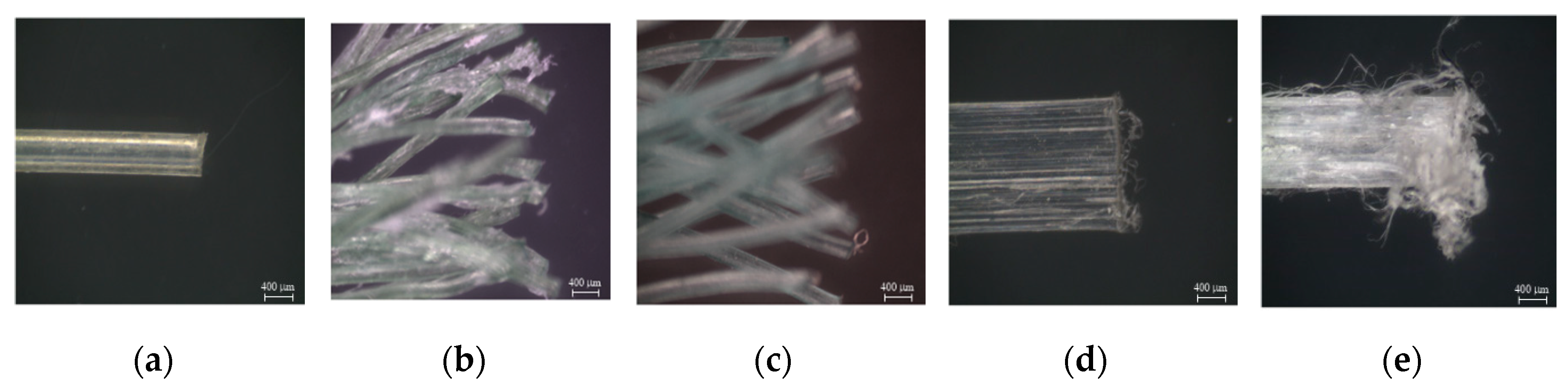
As shown in Figure 8b, the equivalent bond strengths of WFN2, WFN3, CP1, and CP2 were 2.86, 2.46, 0.50, and 5.00 MPa, respectively. Similar to the peak bond strength, CP2 had the highest equivalent strength, while CP1 had the lowest. Unlike the peak bond strength, the equivalent bond strength of WFN2 was higher than that of WFN3. The condition of the fiber end after debonding reflected these results. Figure 11 shows the ends of the fibers after the pullout test. The end of the WFN2 fiber showed surface damage, while the WFN3 fiber did not, indicating that the WFN2 fiber experienced higher stress as the tensile strength of the fiber was reached. Further, the WFN2 fiber slipped more than the 10 mm embedment length, as shown in Figure 5a. Therefore, the equivalent strength of WFN2 was higher than that of WFN3.
7. Conclusions
This study investigated the interfacial bond strength of five types of synthetic macro-fibers: monofilament WFN fiber (WFN1), two types of multifilament bundled WFN fiber (WFN2 and WFN3), and two types of CP fibers (CP1 and CP2) embedded in cement mortar. The peak bond strength based on the pullout load and the equivalent bond strength based on the pullout energy were calculated to compare the bond characteristics without the influence of the fiber geometry. The following conclusions can be drawn:
CP2 demonstrated the best pullout resistance, in terms of both peak pullout load and pullout energy, because of its high tensile strength (450 MPa) and the extensive fiber damage present after fiber pullout. Although CP1 had the highest tensile strength (620 MPa), it obtained the lowest pullout resistance values because there was almost no damage to the fiber after fiber pullout.
WFN1 could not be tested because its smooth surface prevented it from generating a mechanical bond. Therefore, monofilament WFN would not be recommended for cement mortar reinforcement.
The bundled WFN fiber had a greater contact area with the mortar than did WFN1 and generated a mechanical bond that caused significant damage to both WFN2 and WFN3 during the fiber pullout. Therefore, WFN2 and WFN3 demonstrated higher bond strengths than CP1, which had a smooth surface, and, therefore, less damage to fiber after the pullout.
Among the bundled WFN fibers tested, WFN2 was more efficient than WFN3 because the fiber stress and equivalent bond strength of WFN2 were higher than those of WFN3. Consequently, bundled WFN could be used to reinforce cement mortar.
This study found that due to their high bond strength, bundled WFN fibers could mechanically replace CP fibers for preventing the brittle destruction of cement mortar. However, before utilizing WFN in the construction industry, evaluations of the effect of using the WFN fiber on the durability of cement-based materials are required.
Author Contributions
Conceptualization, M.O.K. and D.J.K.; methodology, M.O.K.; validation, J.K.P. and D.J.K.; investigation, J.K.P.; resources, D.J.K.; writing—original draft preparation, J.K.P.; writing—review and editing, M.O.K.; visualization, J.K.P.; supervision, M.O.K.; project administration, M.O.K.; funding acquisition, M.O.K. All authors have read and agreed to the published version of the manuscript.
Funding
This research work was financially supported by the Korea Institute of Ocean Science and Technology (KIOST), project number PE99833.
Acknowledgments
Gratitude is cordially expressed to the Korea Institute of Ocean Science and Technology (385, Haeyang-ro, Yeongdo-gu, Busan 49111, Korea) and Sejong University (209, Neungdong-ro, Gwangjin-Gu, Seoul 05006, Korea) for conducting the fiber pullout testing.
Conflicts of Interest
The authors declare no conflict of interest.
References
- Naaman, A.E.; Shar, S.R. Pull-out mechanism in steel fibre-reinforced concrete. J. Struct. Div. 1976, 102, 1537–1548. [Google Scholar]
- Morton, J.; Groves, G.W. The cracking of composites consisting of discontinuous ductile fibres in a brittle matrix—Effect of fibre orientation. J. Mater. Sci. 1974, 9, 1436–1445. [Google Scholar] [CrossRef]
- Yin, S.; Tuladhar, R.; Shi, F.; Combe, M.; Collister, T.; Sivakugan, N. Use of macro plastic fibres in concrete: A review. Constr. Build. Mater. 2015, 93, 180–188. [Google Scholar] [CrossRef]
- Banthia, N.; Majdzadeh, F.; Wu, J.; Bindiganavile, V. Fiber synergy in Hybrid Fiber Reinforced Concrete (HyFRC) in flexure and direct shear. Cem. Concr. Compos. 2014, 48, 91–97. [Google Scholar] [CrossRef]
- Kim, M.O.; Bordelon, A.C.; Lee, N.K. Early-age crack widths of thin fiber reinforced concrete overlays subjected to temperature gradients. Constr. Build. Mater. 2017, 148, 492–503. [Google Scholar] [CrossRef]
- Kim, M.O.; Bordelon, A.C. Age-dependent properties of fiber-reinforced concrete for thin concrete overlays. Constr. Build. Mater. 2017, 137, 288–299. [Google Scholar] [CrossRef]
- Kim, M.O.; Bordelon, A.; Lee, M.K.; Oh, B.H. Cracking and failure of patch repairs in RC members subjected to bar corrosion. Constr. Build. Mater. 2016, 107, 255–263. [Google Scholar] [CrossRef]
- Kim, M.O.; Bordelon, A. Fiber Effect on Interfacial Bond between Concrete and Fiber-Reinforced Mortar. Transp. Res. Rec. 2016, 2591, 11–18. [Google Scholar] [CrossRef]
- Kim, M.O.; Bordelon, A. Determination of Total Fracture Energy for Fiber-Reinforced Concrete. ACI Spec. Publ. 2015, 300, 1–16. [Google Scholar]
- Singh, S.; Shukla, A.; Brown, R. Pullout behavior of polypropylene fibers from cementitious matrix. Cem. Concr. Res. 2004, 34, 1919–1925. [Google Scholar] [CrossRef]
- Tran, N.T.; Tran, T.K.; Jeon, J.K.; Park, J.K.; Kim, D.J. Fracture energy of ultra-high-performance fiber-reinforced concrete at high strain rates. Cem. Concr. Res. 2016, 79, 169–184. [Google Scholar] [CrossRef]
- Yoo, D.-Y.; Banthia, N.; Fujikake, K.; Kim, Y.H.; Gupta, R. Fiber-Reinforced Cement Composites: Mechanical Properties and Structural Implications. Adv. Mater. Sci. Eng. 2018, 2018, 1–2. [Google Scholar] [CrossRef] [Green Version]
- Wang, Y.; Chom, B.S.; Zureick, A.H. Fiber reinforce concrete using recycled carpet industrial waste and its potential use in highway construction. In Proceedings of the Symposium on Recovery & Effective Reuse of Discarded Materials & By-Products for Construction of Highway Facilities, Denver, CO, USA, 19 October 1993; pp. 4111–4117. [Google Scholar]
- Ochi, T.; Okubo, S.; Fukui, K. Development of recycled PET fiber and its application as concrete-reinforcing fiber. Cem. Concr. Compos. 2007, 29, 448–455. [Google Scholar] [CrossRef]
- Kim, S.B.; Yi, N.H.; Kim, H.Y.; Kim, J.-H.J.; Song, Y.-C. Material and structural performance evaluation of recycled PET fiber reinforced concrete. Cem. Concr. Compos. 2010, 32, 232–240. [Google Scholar] [CrossRef]
- García, D.; Vegas, I.; Cacho, I. Mechanical recycling of GFRP waste as short-fiber reinforcements in microconcrete. Constr. Build. Mater. 2014, 64, 293–300. [Google Scholar] [CrossRef]
- Abdul Awal, A.S.M. Strength, Modulus of elasticity and shrinkage behaviour of concrete containing waste carpet fiber. Int. J. Geomate 2015, 9, 1441–1446. [Google Scholar] [CrossRef]
- Gu, L.; Ozbakkaloglu, T. Use of recycled plastics in concrete: A critical review. Waste Manag. 2016, 51, 19–42. [Google Scholar] [CrossRef]
- Bertelsen, I.M.G.; Ottosen, L.M. Engineering properties of fibers from waste fishing nets. In Proceedings of the International Conference on Materials, Systems and Structures in Civil Engineering: Conference Workshop on Cold Region Engineering, Technical University of Denmark, Lyngby, Denmark, 22 August 2016; pp. 7–16. [Google Scholar]
- Spadea, S.; Farina, I.; Carrafiello, A.; Fraternali, F. Recycled nylon fibers as cement mortar reinforcement. Constr. Build. Mater. 2015, 80, 200–209. [Google Scholar] [CrossRef] [Green Version]
- Orasutthikul, S.; Unno, D.; Yokota, H. Effectiveness of recycled nylon fiber from waste fishing net with respect to fiber reinforced mortar. Constr. Build. Mater. 2017, 146, 594–602. [Google Scholar] [CrossRef] [Green Version]
- Park, J.K.; Kim, D.J.; Kim, M.O. Mechanical behavior of waste fishing net fiber-reinforced cementitious composites subjected to direct tension. J. Build. Eng. 2020, 33, 101622. [Google Scholar] [CrossRef]
- Nili, M.; Afroughsabet, V. The effects of silica fume and polypropylene fibers on the impact resistance and mechanical properties of concrete. Constr. Build. Mater. 2010, 24, 927–933. [Google Scholar] [CrossRef]
- Yin, S.; Tuladhar, R.; Shanks, R.A.; Collister, T.; Combe, M.; Jacob, M.; Tian, M.; Sivakugan, N. Fiber preparation and mechanical properties of recycled polypropylene for reinforcing concrete. J. Appl. Polym. Sci. 2015, 132, 41866. [Google Scholar] [CrossRef]
- Betterman, L.R.; Ouyang, C.; Shah, S.P. Fiber-matrix interaction in microfiber-reinforced mortar. Adv. Cem. Based Mater. 1995, 2, 53–61. [Google Scholar] [CrossRef]
- Park, J.K.; Ngo, T.T.; Kim, D.J. Interfacial bond characteristics of steel fibers embedded in cementitious composites at high rates. Cem. Concr. Res. 2019, 123, 105802. [Google Scholar] [CrossRef]
- Li, V.C.; Wang, S.; Backer, S. Effect of inclining angle, bundling and surface treatment on synthetic fibre pull-out from a cement matrix. Composites 1990, 21, 132–140. [Google Scholar] [CrossRef]
- Ferrara, G.; Pepe, M.; Martinelli, E.; Tolêdo Filho, R.D. Influence of an impregnation treatment on the morphology and mechanical behaviour of flax yarns embedded in hydraulic lime mortar. Fibers 2019, 7, 30. [Google Scholar] [CrossRef] [Green Version]
- Aljewifi, H.; Fiorio, B.; Gallias, J.L. Pull-out behaviour of a glass multi-filaments yarn embedded in a cementitious matrix. In Computational Modeling of Concrete Structures. EURO-C 2010; Bićanić, N., de Borst, R., Mang, H., Meschke, G., Eds.; CRC Press: Boca Raton, FL, USA, 2010. [Google Scholar]
- Di Maida, P.; Radi, E.; Sciancalepore, C.; Bondioli, F. Pullout behavior of polypropylene macro-synthetic fibers treated with nano-silica. Constr. Build. Mater. 2015, 82, 39–44. [Google Scholar] [CrossRef] [Green Version]
- American Society for Testing and Materials. Standard Test Method for Compressive Strength of Hydraulic Cement Mortars (Using 2-in. Or [50-mm] Cube Specimens, ASTM C109/C109M-16a; ASTM International: West Conshohocken, PA, USA, 2016. [Google Scholar]
- Park, J.K.; Kim, S.-W.; Kim, D.J. Matrix-strength-dependent strain-rate sensitivity of strain-hardening fiber-reinforced cementitious composites under tensile impact. Compos. Struct. 2017, 162, 313–324. [Google Scholar] [CrossRef]
- Babafemi, A.J.; du Plessis, A.; Boshoff, W.P. Pull-out creep mechanism of synthetic macro fibres under a sustained load. Constr. Build. Mater. 2018, 174, 466–473. [Google Scholar] [CrossRef]
- Ottosen, L.M.; Svensson, S.J.; Bertelsen, I.M.G. Discarded nylon fishing nets as fibre reinforcement in cement mortar. WIT Trans. Ecol. Environ. 2019, 231, 245–256. [Google Scholar]
- Kim, D.J.; El-Tawil, S.; Naaman, A.E. Correlation between Single Fiber Pullout and Tensile Response of Frc Composites with High Strength Steel Fibers. In Proceedings of the Fifth International RILEM Workshop on High Performance Fiber Reinforced Cement Composites (HPFRCC5), Mainz, Germany, 10–13 July 2007; pp. 67–76. [Google Scholar]
Figure 1.
Typical single-fiber pullout behavior [26].
Figure 1.
Typical single-fiber pullout behavior [26].

Figure 2.
Exposed surface of a multifilament bundled fiber [27]: (a) Unit triangular element in a hexagonally packed bundle; (b) Surface roughness of a bundled fiber.
Figure 2.
Exposed surface of a multifilament bundled fiber [27]: (a) Unit triangular element in a hexagonally packed bundle; (b) Surface roughness of a bundled fiber.

Figure 3.
Geometry of the WFN fibers and CP fibers: (a) WFN1; (b) WFN2; (c) WFN3; (d) CP1; (e) CP2. WFN, waste fishing net; CP, commercial polypropylene.
Figure 3.
Geometry of the WFN fibers and CP fibers: (a) WFN1; (b) WFN2; (c) WFN3; (d) CP1; (e) CP2. WFN, waste fishing net; CP, commercial polypropylene.

Figure 4.
Single-fiber pullout test setup [26].
Figure 4.
Single-fiber pullout test setup [26].

Figure 5.
Pullout load versus slip curves of WFN and CP fibers: (a) WFN2; (b) WFN3; (c) CP1; (d) CP2.
Figure 5.
Pullout load versus slip curves of WFN and CP fibers: (a) WFN2; (b) WFN3; (c) CP1; (d) CP2.

Figure 6.
Effect of using different fiber types on the pullout resistance: (a) Peak pullout load; (b) Fiber stress; (c) Pullout energy.
Figure 6.
Effect of using different fiber types on the pullout resistance: (a) Peak pullout load; (b) Fiber stress; (c) Pullout energy.

Figure 7.
Assumptions underlying the equivalent bond strength calculation [30].
Figure 7.
Assumptions underlying the equivalent bond strength calculation [30].
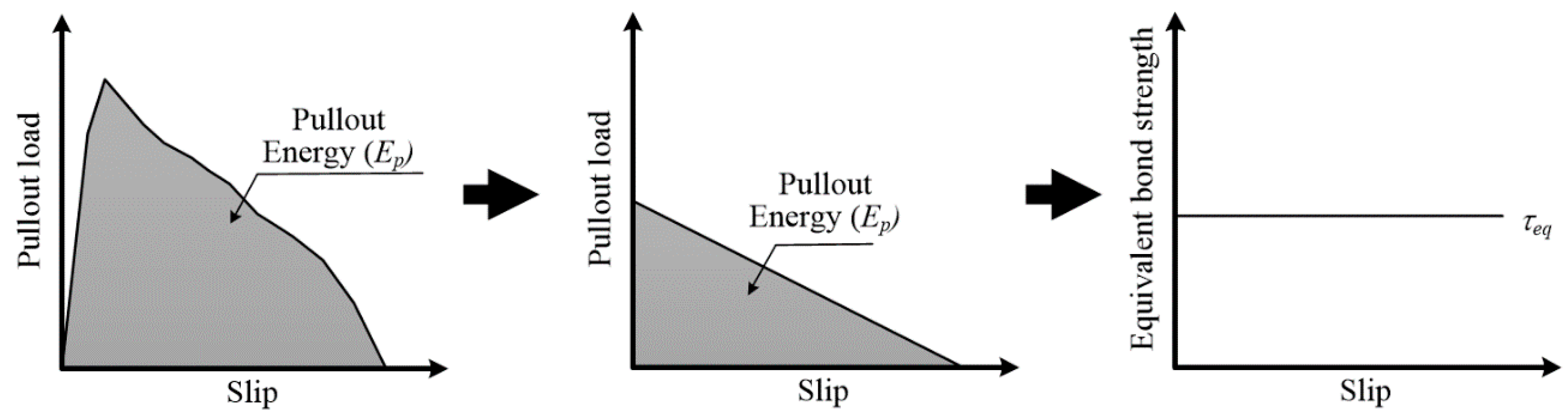
Figure 8.
Effect of the different fibers on the: (a) Peak bond strength and (b) Equivalent bond strength.
Figure 8.
Effect of the different fibers on the: (a) Peak bond strength and (b) Equivalent bond strength.

Figure 9.
Surfaces of the macro-fibers before the pullout testing: (a) WFN1; (b) WFN2; (c) WFN3; (d) CP1; (e) CP2 [22].
Figure 9.
Surfaces of the macro-fibers before the pullout testing: (a) WFN1; (b) WFN2; (c) WFN3; (d) CP1; (e) CP2 [22].
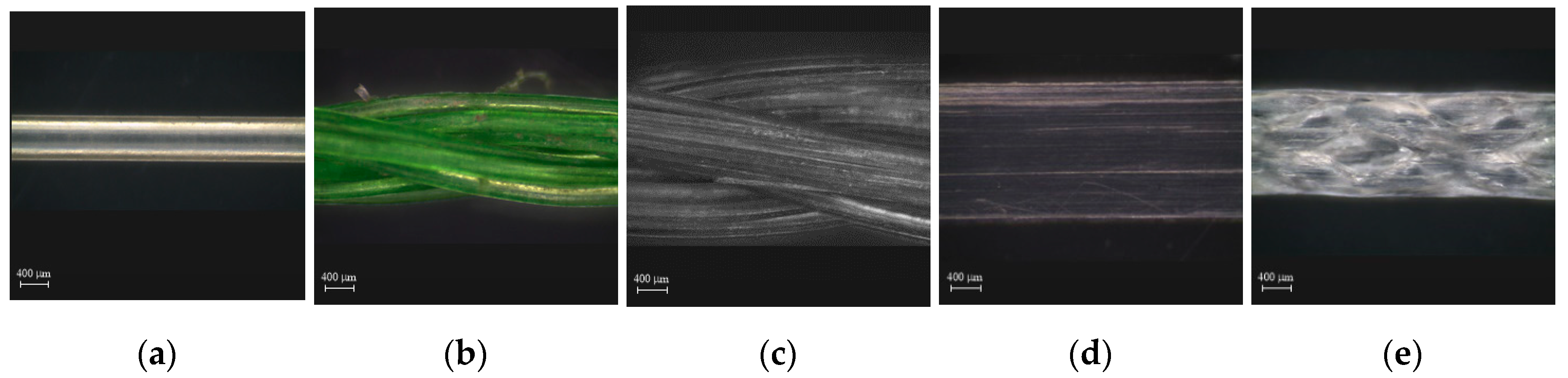
Figure 10.
Surfaces of the macro-fibers after the pullout testing: (a) WFN1; (b) WFN2; (c) WFN3; (d) CP1; (e) CP2.
Figure 10.
Surfaces of the macro-fibers after the pullout testing: (a) WFN1; (b) WFN2; (c) WFN3; (d) CP1; (e) CP2.
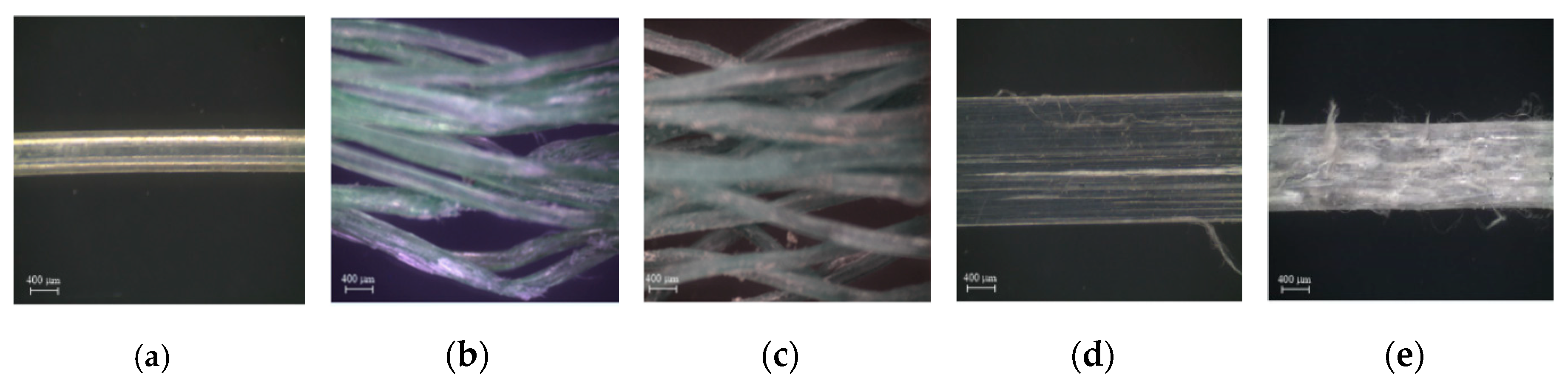
Figure 11.
Ends of the macro-fibers after the pullout testing: (a) WFN1; (b) WFN2; (c) WFN3; (d) CP1; (e) CP2.
Figure 11.
Ends of the macro-fibers after the pullout testing: (a) WFN1; (b) WFN2; (c) WFN3; (d) CP1; (e) CP2.

Table 1.
Matrix composition by weight ratio and compressive strength [22].
Table 1.
Matrix composition by weight ratio and compressive strength [22].
| Cement (Type I) | Water | Silica Sand | Superplasticizer | Compressive Strength (MPa) | Tensile Strength (MPa) |
|---|---|---|---|---|---|
| 1.0 | 0.45 | 1.5 | 0.0009 | 71.9 | 1.53 |
Table 2.
Properties of the synthetic fibers.
| Notation | Fiber Type | Diameter of Filament (mm) | Number of Filaments | Embedded Length (mm) | Tensile Strength (MPa) |
|---|---|---|---|---|---|
| WFN1 | Monofilament | 0.45 | 1 | 10 | 305 |
| WFN2 | Multifilament (Bundled) | 0.2 | 18 | 10 | 188 |
| WFN3 | Multifilament (Bundled) | 0.2 | 30 | 10 | 173 |
| CP1 | Smooth | 1.4 × 0.1 a | 1 | 10 | 620 |
| CP2 | Embossed | 1.1 × 0.6 a | 1 | 10 | 450 |
WFN = Waste Fishing Net; CP = Commercial Polypropylene; a Rectangular section.
Table 3.
Pullout test results.
| Notation | Specimens | Peak Pullout Load Ppeak (N) | Fiber Stress σF (MPa) | Slip at Peak Load ΔPeak (mm) | Pullout Energy EP (N·mm) |
|---|---|---|---|---|---|
| WFN1 | SP1 | N.A. | N.A. | N.A. | N.A. |
| SP2 | N.A. | N.A. | N.A. | N.A. | |
| SP3 | N.A. | N.A. | N.A. | N.A. | |
| Average | N.A. | N.A. | N.A. | N.A. | |
| WFN2 | SP1 | 102.10 | 180.55 | 3.63 | 623.64 |
| SP2 | 111.45 | 197.09 | 3.55 | 664.57 | |
| SP3 | 96.30 | 170.30 | 2.69 | 646.89 | |
| SP4 | 103.65 | 183.29 | 2.77 | 577.68 | |
| Average | 103.38 | 182.81 | 3.16 | 628.19 | |
| WFN3 | SP1 | 147.55 | 156.56 | 1.96 | 693.67 |
| SP2 | 162.45 | 172.36 | 1.38 | 809.92 | |
| SP3 | 136.95 | 145.31 | 1.74 | 658.35 | |
| SP4 | 130.20 | 138.15 | 1.36 | 634.44 | |
| Average | 144.29 | 153.09 | 1.61 | 699.09 | |
| CP1 | SP1 | 14.50 | 103.57 | 1.34 | 66.01 |
| SP2 | 15.70 | 112.14 | 1.19 | 83.87 | |
| SP3 | 13.50 | 96.43 | 1.17 | 65.50 | |
| SP4 | 15.00 | 107.14 | 0.87 | 86.15 | |
| Average | 14.68 | 104.82 | 1.14 | 75.38 | |
| CP2 | SP1 | 168.65 | 255.53 | 2.14 | 888.23 |
| SP2 | 163.20 | 247.27 | 2.07 | 818.15 | |
| SP3 | 169.25 | 256.44 | 2.00 | 994.46 | |
| SP4 | 152.45 | 230.98 | 2.06 | 697.86 | |
| Average | 163.39 | 247.56 | 2.07 | 849.68 |
N.A.: Not available.
Table 4.
Theoretical consideration of multifilament WFN fibers.
| Notation | df (mm) | N (ea) | Total Diameter (mm) | rA - | R (mm) | pexposed (mm) | p (mm) |
|---|---|---|---|---|---|---|---|
| WFN2 | 0.2 | 18 | 1.0 | 0.907 | 0.445 | 4.397 | 3.142 |
| WFN3 | 0.2 | 30 | 1.5 | 0.907 | 0.575 | 5.676 | 4.712 |
Table 5.
Calculated bond strength.
| Notation | Specimens | Peak Bond Strength (MPa) | Equivalent Bond Strength (MPa) |
|---|---|---|---|
| WFN2 | SP1 | 2.32 | 2.84 |
| SP2 | 2.53 | 3.02 | |
| SP3 | 2.19 | 2.94 | |
| SP4 | 2.36 | 2.63 | |
| Average | 2.36 | 2.86 | |
| WFN3 | SP1 | 2.60 | 2.44 |
| SP2 | 2.86 | 2.85 | |
| SP3 | 2.41 | 2.32 | |
| SP4 | 2.29 | 2.24 | |
| Average | 2.54 | 2.46 | |
| CP1 | SP1 | 0.48 | 0.44 |
| SP2 | 0.52 | 0.56 | |
| SP3 | 0.45 | 0.44 | |
| SP4 | 0.50 | 0.57 | |
| Average | 0.49 | 0.50 | |
| CP2 | SP1 | 4.96 | 5.22 |
| SP2 | 4.80 | 4.81 | |
| SP3 | 4.98 | 5.85 | |
| SP4 | 4.48 | 4.11 | |
| Average | 4.81 | 5.00 |
© 2020 by the authors. Licensee MDPI, Basel, Switzerland. This article is an open access article distributed under the terms and conditions of the Creative Commons Attribution (CC BY) license (http://creativecommons.org/licenses/by/4.0/).
Share and Cite
MDPI and ACS Style
Park, J.K.; Kim, M.O.; Kim, D.J. Pullout Behavior of Recycled Waste Fishing Net Fibers Embedded in Cement Mortar. Materials 2020, 13, 4195. https://doi.org/10.3390/ma13184195
AMA Style
Park JK, Kim MO, Kim DJ. Pullout Behavior of Recycled Waste Fishing Net Fibers Embedded in Cement Mortar. Materials. 2020; 13(18):4195. https://doi.org/10.3390/ma13184195
Chicago/Turabian StylePark, Jun Kil, Min Ook Kim, and Dong Joo Kim. 2020. "Pullout Behavior of Recycled Waste Fishing Net Fibers Embedded in Cement Mortar" Materials 13, no. 18: 4195. https://doi.org/10.3390/ma13184195
Note that from the first issue of 2016, this journal uses article numbers instead of page numbers. See further details here.