In Search of the Optimal Conditions to Process Shape Memory Alloys (NiTi) Using Fused Filament Fabrication (FFF)


Abstract
1. Introduction
2. Materials and Methods
3. Results and Discussion
4. Conclusions
Author Contributions
Funding
Conflicts of Interest
References
- Buehler, W.J.; Gilfrich, J.V.; Wiley, R.C. Effect of Low-Temperature Phase Changes on the Mechanical Properties of Alloys near Composition TiNi. J. Appl. Phys. 1963, 34. [Google Scholar] [CrossRef]
- Walker, J.; Elahinia, M.; Haberland, C. An investigation of process parameters on selective laser melting of nitinol. In ASME 2013 Conference on Smart Materials, Adaptive Structures and Intelligent Systems; American Society of Mechanical Engineers: Snowbird, Utah, USA, 2013. [Google Scholar]
- Meier, H.; Haberland, C.; Frenzel, J. Structural and functional properties of NiTi shape memory alloys produced by selective laser melting. In Innovative Developments in Design and Manufacturing: Advanced Research in Virtual and Rapid Prototyping; Taylor & Francis Group: Leiria, Portugal, 2011; pp. 291–296. [Google Scholar]
- Frenzel, J.; George, E.P.; Dlouhy, A.; Somsen, C.; Wagner, M.F.X.; Eggeler, G. Influence of Ni on martensitic phase transformations in NiTi shape memory alloys. Acta Mater. 2010, 58, 3444–3458. [Google Scholar] [CrossRef]
- Elahinia, M.; Moghaddam, N.S.; Andani, M.T.; Amerinatanzi, A.; Bimber, B.A.; Hamilton, R.F. Fabrication of NiTi through additive manufacturing: A review. Prog. Mater.Sci. 2016, 83, 630–663. [Google Scholar] [CrossRef]
- Dabbaghi, H.; Safaei, K.; Nematollahi, M.; Bayati, P.; Elahinia, M. Additively Manufactured NiTi and NiTiHf Alloys: Estimating Service Life in High-Temperature Oxidation. Materials 2020, 13, 2104. [Google Scholar] [CrossRef]
- Cherian, J.C.; Groarke, R.; O’Toole, K.; Brabazon, D. Advances in Selective Laser Melting of Nitinol Shape Memory Alloy Part Production. Materials 2019, 12, 809. [Google Scholar] [CrossRef]
- Meier, H.; Haberland, C.; Frenzel, J.; Zarnetta, R. Selective Laser Melting of NiTi Shape Memory Components. In Innovative Developments in Design and Manufacturing—Advanced Research in Virtual and Rapid Prototyping; CRC Press Balkema: Leiria, Portugal, 2009; pp. 233–238. [Google Scholar]
- Bormann, T.; Schumacher, R.; Muller, B.; Mertmann, M.; Wild, M. Tailoring selective laser melting process parameters for NiTi implants. J. Mater. Eng. Perform. 2012, 21, 447–454. [Google Scholar] [CrossRef]
- Bormann, T.; Müller, B.; Schinhammer, M.; Kessler, A.; Thalmann, P.; Wild, M. Microstructure of selective laser melted nickel–titanium. Mater. Charact. 2014, 94, 189–202. [Google Scholar] [CrossRef]
- Haberland, C.; Elahinia, M.; Walker, J. Additive manufacturing of shape memory devices and pseudoelastic components. In ASME 2013 Conference On Smart Materials, Adaptive Structures And Intelligent Systems; ASME: New York, NY, USA, 2013. [Google Scholar]
- Krone, L.; Mentz, J.; Bram, M.; Buchkremer, H.; Stöver, D.; Wagner, M.; Eggeler, G.; Juhre, D.; Reese, S.; Bogdanski, D.; et al. The Potential of Powder Metallurgy for the Fabrication of Biomaterials on the Basis of Nickel-Titanium: A Case Study with a Staple Showing Shape Memory Behaviour. Adv. Eng. Mater. 2005, 7, 613–619. [Google Scholar] [CrossRef]
- Krone, L.; Schüller, E.; Bram, M.; Hamed, O.; Buchkremer, H.; Stöver, D. Mechanical behaviour of NiTi parts prepared by powder metallurgical methods. Mater. Sci. Eng. 2003, 378, 185–190. [Google Scholar] [CrossRef]
- Test Certificate. LPW-NITI-AZAR; LPW Technology Ltd.: Philadelphia, PA, USA, 2018. [Google Scholar]
- Schölle, E.; Krone, L.; Bram, M.; Buchkremer, H.; Ståaver, D. Metal injection molding of shape memory alloys using prealloyed NiTi powders. J. Mater. Sci. 2005, 40, 4231–4238. [Google Scholar] [CrossRef]
- Köhl, M.; Habijan, T.; Bram, M.; Buchkremer, H.; Stöver, D.; Köller, M. Powder Metallurgical Near-Net-Shape Fabrication of Porous NiTi Shape Memory Alloys for Use as Long-Term Implants by the Combination of the Metal Injection Molding Process with the Space-Holder Technique. Adv. Eng. Mater. 2009, 11, 959–968. [Google Scholar] [CrossRef]
- Köhl, M.; Bram, M.; Moser, M.; Buchkremer, H.; Beck, T.; Stöver, D. Characterization of porous, net-shaped NiTi alloy regarding its damping and energy-absorbing capacity. Mater. Sci. Eng. 2011, 528, 2454–2462. [Google Scholar] [CrossRef]
- Bidaux, E.J.; Amherd, H.A.; Girard, H.; Rodríguez, A.M.; Reynard, L.; Chevallier, J.; Aeby, F.; Charles, G.J.; Carreño, M.E. Metal injection moulding of superelastic TiNi parts. Key Eng. Mater. 2016, 704, 173–182. [Google Scholar] [CrossRef]
- Miyake, K.; Hirata, Y.; Shimonosono, T.; Sameshima, S. The Effect of Particle Shape on Sintering Behavior and Compressive Strength of Porous Alumina. Materials 2018, 11, 1137. [Google Scholar] [CrossRef]
- Kadir, A.R.A.; Razali, R.; Nor, N.; Subuki, I.; Ismail, M. The Effect of Particles Shape and Size on Feedstock Flowibility and Chemical content of As-sintered NiTi Alloys. Mater. Sci. Eng. 2018, 358, 012064. [Google Scholar]
- Barreiros, M.F.; Vieira, M.T.; Castanho, J.M. Fine tuning injection feedstock by nano coating SS powder. Metal. Powder Rep. 2009, 64, 18–21. [Google Scholar] [CrossRef]
- Vieira, T.M.; Martins, A.G.; Barreiros, F.M.; Matos, M.; Castanho, J.M. Surface modification of stainless steel powders for microfabrication. J. Mater. Process. Technol. 2008, 201, 651–656. [Google Scholar] [CrossRef]
- Cerejo, F. Development of Filamentos for 3D Printing of Steel Parts. Master’s Thesis, University of Coimbra, Coimbra, Portugal, 2018. [Google Scholar]
- Dassault, S. Solidworks Premium Research. Available online: https://www.3ds.com/products-services/solidworks/ (accessed on 10 May 2019).
- Ultimaker, B.V. Ultimaker Cura 4.1. Available online: https://ultimaker.com/en/products/ultimaker-cura-software (accessed on 5 March 2019).
- Optimising your Design for MIM Production. Available online: https://www.pim-international.com/metal-injection-molding/optimising-your-design-for-mim-production/ (accessed on 1 August 2020).
- Heaney, D.F. Handbook of Metal. Injection Molding. In Metals and Surface Engineering, 2nd ed.; Elsevier: Amsterdam, The Netherlands, 2019. [Google Scholar]
- Bram, M.; Bitzer, M.; Buchkremer, H.; Stöver, D. Reproducibility Study of NiTi Parts Made by Metal Injection Molding. J. Mater. Eng. Perform. 2012. [Google Scholar] [CrossRef]
- Heaney, D.F. Handbook Of Metal Injection Molding. In Woodhead Publishing in Materials; Elsevier: Amsterdam, The Netherlands, 2012. [Google Scholar]
- Bram, M.; Manuel, K.; Buchkremer, H.; Stöver, D. Mechanical Properties of Highly Porous NiTi Alloys. J. Mater. Eng. Perform. 2010, 20, 522–528. [Google Scholar] [CrossRef]
- Otsuka, K.; Ren, X. Physical metallurgy of Ti–Ni-based shape memory alloys. Prog. Mater. Sci. 2005, 50, 511–678. [Google Scholar] [CrossRef]
- Alnomani, A.S.; Fadhel, E.Z.; Mehatlaf, A.A. Prepare Nitinol Alloys and Improve their Hardness Using Copper as an Alloying Element. Int. J. Appl. Eng. Res. 2017, 12, 4299–4308. [Google Scholar]
- Xu, W.; Rivera-Díaz-del-Castillo, P.E.J.; Wang, W.; Yang, K.; Bliznuk, V.; Kestens, L.A.I.; van der Zwaag, S. Genetic design and characterization of novel ultra-high-strength stainless steels strengthened by Ni3Ti intermetallic nanoprecipitates. Acta Mater. 2010, 58, 3582–3593. [Google Scholar] [CrossRef]
- Verdian, M.M.; Raeissi, K.; Salehi, M.; Sabooni, S. Characterization and corrosion behavior of NiTi–Ti2Ni–Ni3Ti multiphase intermetallics produced by vacuum sintering. Vacuum 2011, 86, 91–95. [Google Scholar] [CrossRef]
- Yoshida, M.; Shiraishi, H.; Ikk, N. Microstructure and Mechanical Properties of NiTi2-TiB Composite Fabricated by Spark Plasma Sintering. World J. Eng. Technol. 2015, 3, 84–88. [Google Scholar] [CrossRef]
- Wang, M.H.; Liu, Y.F. Microstructure and wear resistance of laser clad Ti5Si3/NiTi2 intermetallic composite coating on titanium alloy. Mater. Sci. Eng. 2002, 338, 126–132. [Google Scholar] [CrossRef]
- Mokgalaka, N.M.; Popoola, A.P.I.; Pityana, S.L. In Situ laser deposition of NiTi intermetallics for corrosion improvement of Ti−6Al−4V alloy. Trans. Nonferrous Met. Soc. China 2015, 25, 3315–3322. [Google Scholar] [CrossRef]
- Li, F.Y.; Tang, S.L.; Gao, Y.M.; Ma, S.Q.; Zheng, Q.L.; Cheng, Y.H. Mechanical and thermodynamic properties of intermetallic compounds in the Ni–Ti system. Int. J. Mod. Phys. B 2017, 31, 1750161. [Google Scholar] [CrossRef]


| Temp (°C) | Holding Time (h) | Atmosphere (Pa) | Post-Processing | Binder/Space Holder (wt %) | CPVC Binder (vol %) | Phases | Ref. |
|---|---|---|---|---|---|---|---|
| 1250 | 10 | Vacuum (1 × 10⁻²) | - |
| 35 |
| [13] |
| 1270 | 5 | Argon Flow | HIP 1050 °C 3 h 195 MPa | ||||
| 1100 | 5 | Vacuum (-) |
|
| - |
| [15] |
| 1200 | |||||||
| 1270 | |||||||
| 1100 | Argon Flow (-) | ||||||
| 1200 | |||||||
| 1270 | |||||||
| 1250 | 10 | Vacuum (-) | - |
| |||
| 1250 | 10 | Vacuum (1 × 10⁻³) | - |
| 20–25 |
| [16] |
| 1250 | 10 | Vacuum (1 × 10⁻³) | - |
| 25–28 |
| [17] |
| 1265 | |||||||
| 1260 | 4 | Argon Flow (-) | - |
| - |
| [18] |
| Parameter | Value |
|---|---|
| Layer height (mm) | 0.2 |
| Wall thickness (mm) | 0.8 |
| Nozzle temperature (°C) | 200 |
| Plate temperature (°C) | 50 |
| Print speed (mm s−1) | 20 |
| Print acceleration (mm s−2) | 100 |
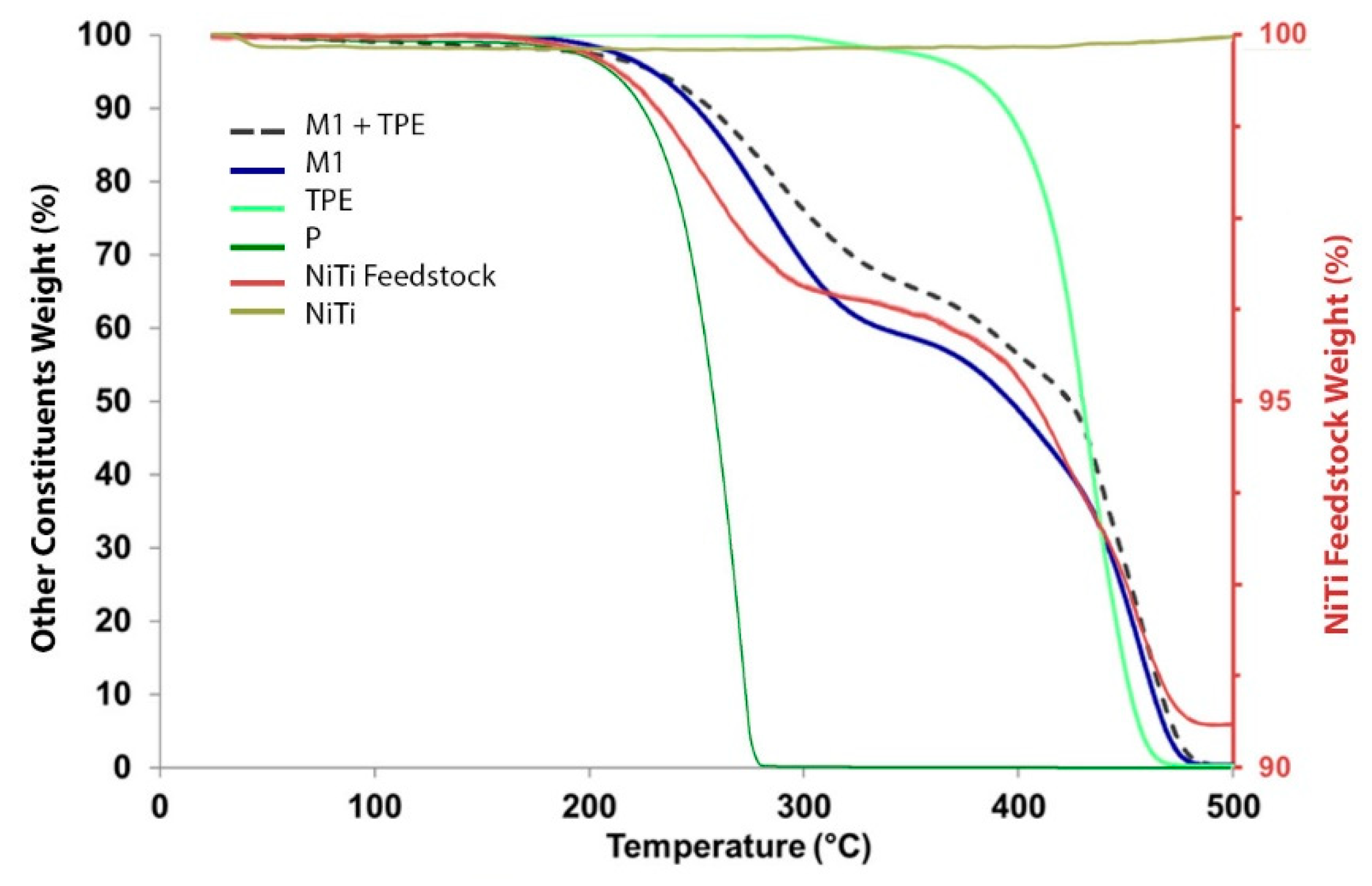
| Feedstock Components | 1st Stage | 2nd Stage | ||
|---|---|---|---|---|
| Ti (°C) | Tf (°C) | Ti (°C) | Tf (°C) | |
| M1 | 200 | 325 | 360 | 485 |
| TPE | 300 | 470 | - | - |
| P | 175 | 285 | - | - |
| M1+TPE | 200 | 305 | 370 | 490 |
| NiTi | - | - | >300 | Light oxidation |
| NiTi + M1 + TPE + P (feedstock) | 150 | 300 | 330 | 490 |
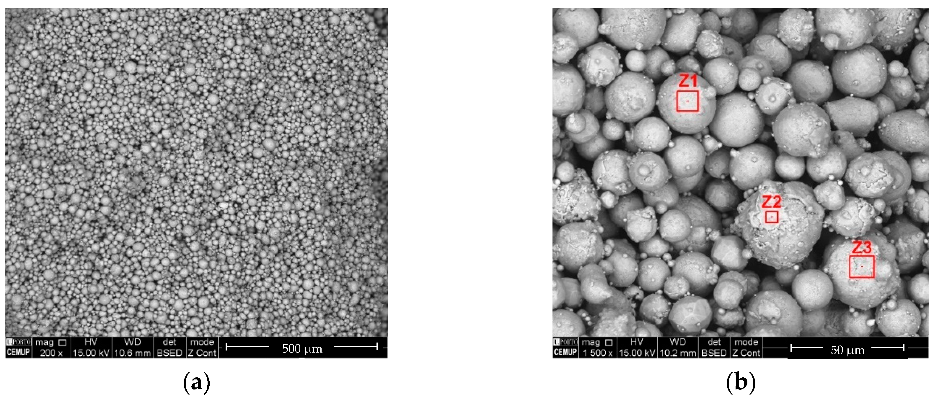
| Ni:Ti (at %) | ||
|---|---|---|
| Z1 | Z2 | Z3 |
| 0.9 | 1.0 | 1.0 |
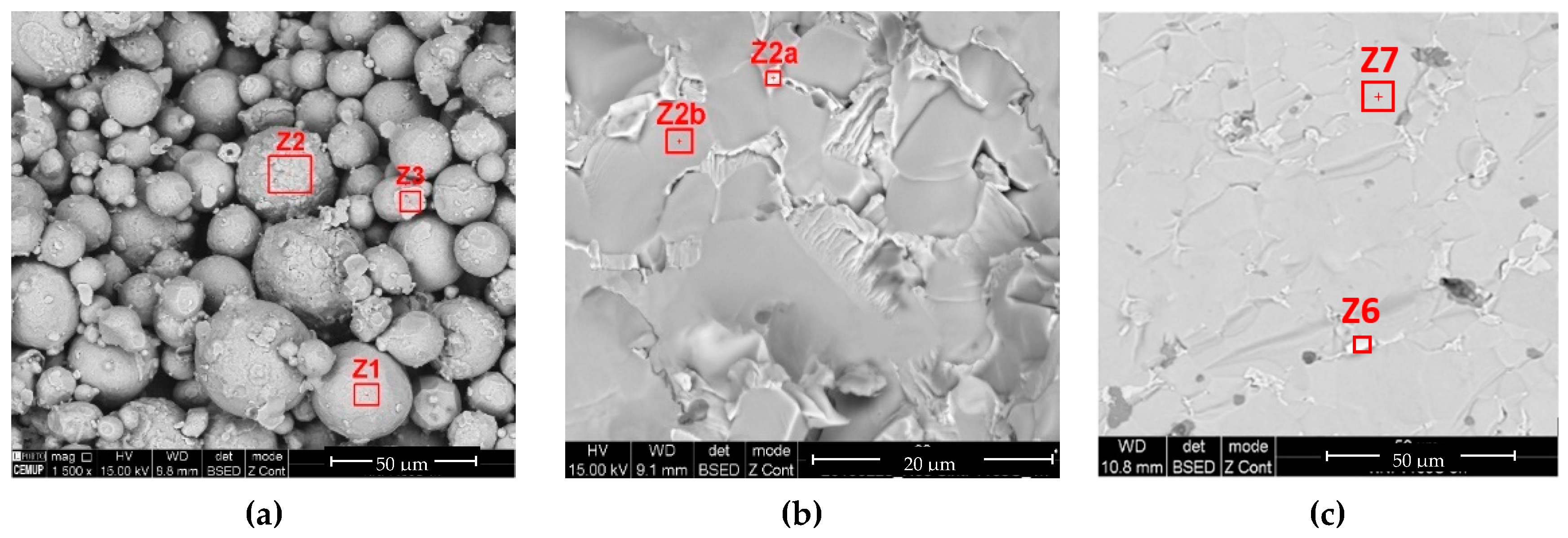
| 1100 °C (1 h) | 1165 °C (1 h) | 1165 °C (5 h) | |||||
|---|---|---|---|---|---|---|---|
| Z1 | Z2 | Z3 | Z2a | Z2b | Z6 | Z7 | |
| Ni:Ti (at %) | 0.6 | 0.6 | 0.6 | 2.6 | 0.6 | 2.9 | 0.6 |
| N° of Specimen | 1 | 2 | 3 | 4 | MH ± SD |
|---|---|---|---|---|---|
| Hardness (HV) | 855 | 939 | 965 | 876 | 887 ± 58 |
Publisher’s Note: MDPI stays neutral with regard to jurisdictional claims in published maps and institutional affiliations. |
© 2020 by the authors. Licensee MDPI, Basel, Switzerland. This article is an open access article distributed under the terms and conditions of the Creative Commons Attribution (CC BY) license (http://creativecommons.org/licenses/by/4.0/).
Share and Cite
Carreira, P.; Cerejo, F.; Alves, N.; Vieira, M.T. In Search of the Optimal Conditions to Process Shape Memory Alloys (NiTi) Using Fused Filament Fabrication (FFF). Materials 2020, 13, 4718. https://doi.org/10.3390/ma13214718
Carreira P, Cerejo F, Alves N, Vieira MT. In Search of the Optimal Conditions to Process Shape Memory Alloys (NiTi) Using Fused Filament Fabrication (FFF). Materials. 2020; 13(21):4718. https://doi.org/10.3390/ma13214718
Chicago/Turabian StyleCarreira, Pedro, Fábio Cerejo, Nuno Alves, and Maria Teresa Vieira. 2020. "In Search of the Optimal Conditions to Process Shape Memory Alloys (NiTi) Using Fused Filament Fabrication (FFF)" Materials 13, no. 21: 4718. https://doi.org/10.3390/ma13214718
APA StyleCarreira, P., Cerejo, F., Alves, N., & Vieira, M. T. (2020). In Search of the Optimal Conditions to Process Shape Memory Alloys (NiTi) Using Fused Filament Fabrication (FFF). Materials, 13(21), 4718. https://doi.org/10.3390/ma13214718