Article

Evaluating the Prospects of Ti-Base Lattice Infiltrated with Biodegradable Zn–2%Fe Alloy as a Structural Material for Osseointegrated Implants—In Vitro Study

Department of Materials Engineering, Ben-Gurion University of the Negev, Beer Sheva 8410501, Israel
*
Author to whom correspondence should be addressed.
Materials 2021, 14(16), 4682; https://doi.org/10.3390/ma14164682
Submission received: 19 July 2021 / Revised: 16 August 2021 / Accepted: 16 August 2021 / Published: 19 August 2021
(This article belongs to the Topic Metallurgical and Materials Engineering)

Abstract

:
The term “osseointegrated implants” mainly relates to structural systems that contain open spaces, which enable osteoblasts and connecting tissue to migrate during natural bone growth. Consequently, the coherency and bonding strength between the implant and natural bone can be significantly increased, for example in operations related to dental and orthopedic applications. The present study aims to evaluate the prospects of a Ti–6Al–4V lattice, produced by selective laser melting (SLM) and infiltrated with biodegradable Zn2%Fe alloy, as an OI–TiZn system implant in in vitro conditions. This combined material structure is designated by this study as an osseointegrated implant (OI–TiZn) system. The microstructure of the tested alloys was examined both optically and using scanning electron microscopy (SEM) and X-ray diffraction (XRD) analysis. The mechanical properties were assessed in terms of compression strength, as is commonly acceptable in cases of lattice-based structures. The corrosion performance was evaluated by immersion tests and electrochemical analysis in terms of potentiodynamic polarization and electrochemical impedance spectroscopy (EIS), all in simulated physiological environments in the form of phosphate buffered saline (PBS) solution. The cytotoxicity was evaluated in terms of indirect cell viability. The results obtained demonstrate the adequate performance of the OI–TiZn system as a non-cytotoxic structural material that can maintain its mechanical integrity under compression, while presenting acceptable corrosion rate degradation.

1. Introduction

The initial definition of osseointegration claimed by Albrektsson et al. [1] was “a direct contact between a loaded implant surface and bone” that can practically improve the mechanical bonding between the permanent implant and the bone [2,3]. Currently, the novelty of producing implants through additive manufacturing (AM) technologies directly from a computer model enable the production of complex implants [4,5,6,7] that can be designated for a specific patient. In particular, this also relates to the capability of producing cellular material in the form of a structural lattice that inherently incorporates open space volume [8]. The structural lattice can then be infiltrated with a biodegradable alloy that slowly dissolves in in vivo conditions. In parallel, bone tissue can grow within the open space generated by the disintegration of the biodegradable alloy. Consequently, this can stimulate osseointegration processes in terms of improving the mechanical bonding between the natural bone and the permanent implant. A relatively similar type of approach was carried out by Balog et al. [9] by producing a composite system using an extruded mixture of Ti and 12% biodegradable Mg powder. They found that the degradation of Mg post-implantation could be replaced by bone tissue that enhances osseointegration. Another example of this type of approach was introduced by Jiang et al. [10]. They demonstrated that a Ti–Mg system obtained by infiltrating pure biodegradable Mg into porous Ti matrix that was produced by applying controlled pressure on Ti wires within a cylindrical preform die.
The commonly preferred additive manufactured metal lattice for osseointegrated implants is Ti–6Al–4V alloy due to its outstanding mechanical properties and excellent biocompatibility [11,12,13,14]. Although Ti–6Al–4V alloy is widely used as a structural material for implants, sometimes it has the tendency to generate problems, such as stress shielding and cytotoxicity that is mainly attributed to the presence of vanadium. Hence, it should be pointed out that other Ti-base alloys are also being considered as of late, such as beta-type Ti–Nb–Zr–Mn alloys [15], Ti25Nb–13Ta–5Zr [16], and Ti–Al–Nb [17]. As for the infiltrated biodegradable metal, there are basically three common alternatives: Fe-base, Mg- base, and Zn-base alloys. Fe-based alloys tend to produce voluminous oxides that repel neighboring tissue, while Mg-based alloys suffer from accelerated corrosion rates that are associated with hydrogen gas evolution and an inherent risk of gas embolism [18,19,20,21,22]. In contrast, Zinc exhibited none of these disadvantageous characteristics [23,24,25,26,27,28]. In fact, Zn tends to stimulate bone growth [29] and act as an antibacterial material that is significantly effective in fighting infections [30,31,32]. However, research carried out by Guillory et al. [33] indicated that pure Zn may suffer from insufficient corrosion degradation rates in in vivo conditions that consequently can provoke fibrous encapsulation and limit the proper dissolution of the implant. To prevent this phenomenon, Fe and other alloying elements were added to pure Zinc in order to accelerate the corrosion rate by a micro-galvanic effect [34]. The present study aims to evaluate the prospects of a Ti–6Al–4V lattice infiltrated with biodegradable Zn–2%Fe alloy as a structural material system for osseointegrated implants in in vitro conditions.

2. Materials and Methods

2.1. Preparation of Osseointegrated Implants (OI–TiZn) System

The OI–TiZn system was made from a permanent Ti–6Al–4V lattice produced by AM, which was subsequently infiltrated by a biodegradable Zn–2%Fe alloy. The Ti–6Al–4V lattice was fabricated by an SLM process using an EOS-EOSINT M280 facility equipped with a 200 W Nd-YAG laser. The particle size of the Ti–6Al–4V powder was between 20–45 µm. The laser beam diameter was 60 µm, the scanning velocity was 7000 mm/s, the hatch spacing was 0.2 mm, and the building layer thickness was 30 µm. The SLM scanning direction rotation was 45 degrees, and the lattice unit cell was in the form of a cubic structure with a 2.5 mm cell parameter and a rod diameter of 1 mm. All the AM lattices were manufactured in the Z-direction and in accordance with ASTM standard 52921-13. The selection of Zn–2%Fe as the biodegradable alloy mainly relates to the relative advantage of this alloy composition in terms of corrosion degradation [18,34]. This selection aims to avoid the danger of insufficient corrosion degradation rates, which can promote fibrous encapsulation and limit the dissolution of the infiltrated alloy [33]. The Zn–2%Fe was produced by gravity casting using pure Zn ingots (99.99%) and pure Fe (99%) powder with a mean grain size of 44 microns. The casting process of Zn–2%Fe was carried out in a graphite crucible and included the following stages: (i) re-melting of pure Zn at 750 °C, and (ii) adding Fe powder with subsequent stirring every 30 min for 3 h [18]. Prior to the infiltration of the biodegradable Zn alloy, the Ti alloy lattice was pre-heated at 400 °C for 1 h. The infiltration process was carried out by immersing the Ti alloy lattice in molten Zn alloy at a temperature above 700 °C within a steel die. In order to secure the proper filling of the Ti-base lattice, the infiltration process was accompanied by intensive shaking.

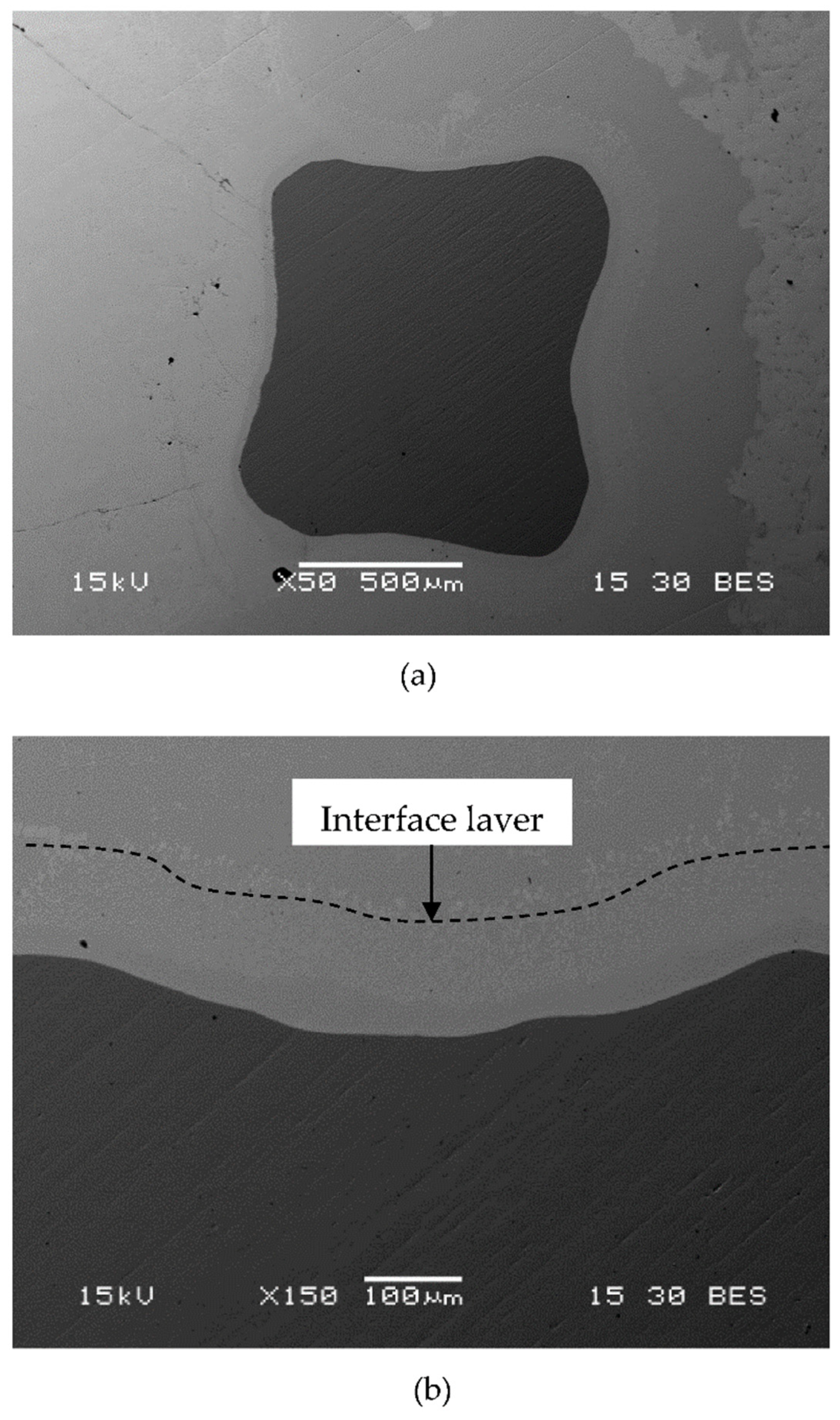
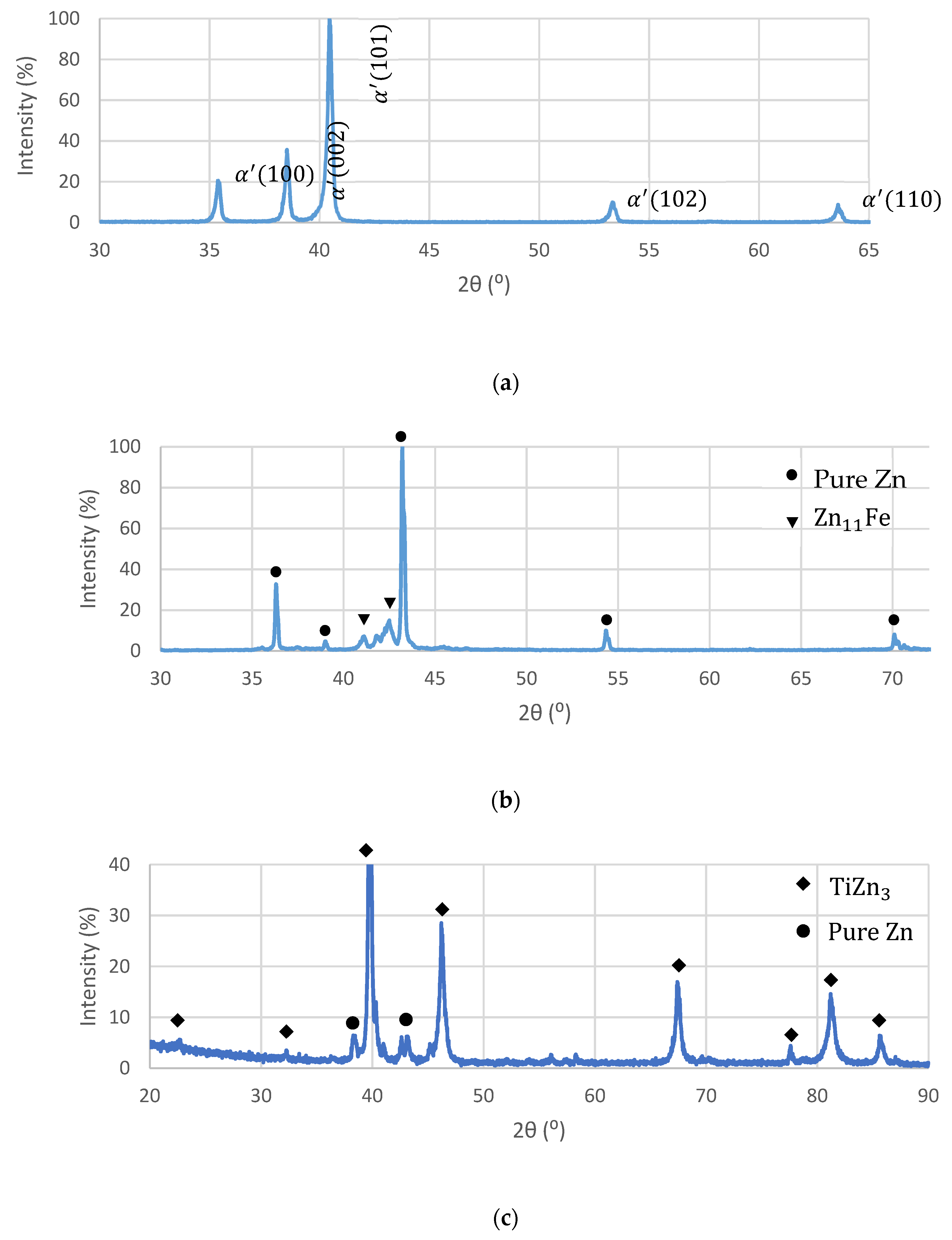
2.2. Microstructure Examinations

The microstructure of the tested materials was examined using JSM-5600 (Tokyo, Japan) scanning electron microscopy (SEM) integrated with an energy dispersive X-ray spectroscopy (EDS) detector (Thermo Fisher Scientific, Waltham, MA, USA) for localized chemical composition analysis with a spot size of 1 μ m [35]. Phase identification was carried out by X-ray diffraction (XRD) analysis, using an X-ray diffractometer (RIGAKU-2100H (Tokyo, Japan) with Cu–K α . Diffraction patterns were generated in the range of 20°–90° at 40 kV, 30 mA, and a scanning rate of 0.02 ° /min. The additively manufactured Ti6Al4V lattice and biodegradable Zn–2%Fe alloy were separately tested as monolithic bulk materials. In order to examine the phases composing the interface between the Ti lattice and the biodegradable Zn-based alloy, the OI–TiZn system was tested in the form of powder subsequent to the removal of intact Ti-base lattice rods. Prior to the XRD analysis, the final powder was ground to obtain a fine grain size of about 100 μm.

2.3. Compression Strength

The mechanical properties of the Ti-lattice and the OI–TiZn system were evaluated in terms of compressive strength, as is commonly acceptable in analyzing three dimensional lattices [10,36]. This was carried out using a Hounsfield H25 KT testing facility with a crosshead-speed of 0.5 mm/min. The test specimens had a cylindrical shape with dimensions of a 10 mm diameter and a 20 mm length, and were obtained by an electro-erosion cutting machine (ARTA 123Pro EDM).

2.4. Immersion Test

The corrosion resistance of the OI–TiZn system and of the biodegradable Zn–2%Fe alloy in equilibrium conditions were examined in terms of immersion tests for 14 days. The testing solution was phosphate buffered saline (PBS) and the temperature was 37 °C, respectively, to simulate typical physiological environmental conditions in accordance with the ASTM ID: G31-72 standard. The specimens for the immersion tests were in the form of cylindrical rods with a 10 mm diameter and an 8 mm length. The specimens were produced by an ARTA 123Pro EDM electro-erosion cutting machine.
The corrosion rate was calculated according to the following equation:
C R = W A · T · D
where W is the weight loss, A is the exposed area, T is the duration time, and D is the density of the specimen.

2.5. Electrochemical Behavior

The electrochemical behavior of the tested materials was evaluated using a Bio-Logic SP-200 potentiostat equipped with EC-Lab software V11.18. This was also carried out in the PBS solution using a three-electrode cell that included a working electrode with an exposed area of 1 cm2, a saturated calomel electrode (SCE) as a reference electrode, and a platinum counter electrode. The scanning rate of potentiodynamic polarization analysis was 1 mV/s. The electrochemical impedance spectroscopy (EIS) analysis was carried out within the range of 10 kHz–100 MHz at 10 mV amplitude. Prior to all electrochemical analysis, the samples were polished to 1200 grit. The corrosion rate was evaluated by Tafel extrapolation [37].

2.6. Cytotoxicity Testing

Cytotoxicity testing was carried out by evaluating the effect of indirect extract on cell metabolic activity according to the ISO 10993-5/12 standard. The cytotoxicity analysis was conducted using Mus musculus (mouse) 4T1 cells, due to their relatively increased sensitivity to toxic effects. In fact, those cells are significantly more active than primary cells, and consequently more sensitive to toxic conditions. Prior to the cytotoxicity tests, Ti–6Al–4V samples produced by an SLM process and OI–TiZn samples—both having a diameter of 7.9 mm and a length of 2 mm—underwent the following treatments: (i) polished up to 4000 grit, (ii) cleaned in ethanol for 10 min, (iii) cleaned in acetone for 5 min, and (iv) sterilized in UV light for 1 h on each side. The required extract was obtained by immersing the related specimens in Dulbecco Modified Eagle’s Medium (DMEM) solution with 4.5 g/L D-Glucose, 10% Fetal Bovine Serum (FBS), 4 mM L-Glutamine, 1 mM Sodium Pyruvate (SP), and 1% Penicillin Streptomycin Neomycin (PSN) antibiotic mixture under a 5% CO2 humidified atmosphere for 24 h at 37 °C. The surface area to volume extraction ratio was 1.25 cm 2 /mL. The extracts were then collected and filtered using a PVDF membrane of 0.45 μm. The 4T1 cells were seeded in 96-well tissue culture plates, in a concentration of 5000 cells per well, and incubated for 24 h to allow for proper rehabilitation. The cells’ medium was then replaced by 100 μL of the following extracts (4 wells of each group): Ti–6Al–4V as the control group, and OI–TiZn extracts, diluted to 1:10 (10%) to correspond to the biological ability to naturally dilute and rid excesses of Zn [38,39]. As additional positive and negative control groups, 4 wells’ mediums were replaced with 100 μL of only DMEM, and 4 wells’ mediums were replaced with 100 μL of 90% DMEM and 10% DMSO, respectively. Two identical 96-well plates were incubated for 24 h and 48 h. The cell viability was assessed using a Cell Proliferation Kit (XTT, Biological Industry, Beit Haemek, Israel). According to this process, each sample (in addition to 3 blank wells as reference) was incubated for 2 h in 100 μL DMEM, 50 μL reagent, and 1 μL activator. The color transformation was measured spectrophotometrically at 490 nm using a microplate reader (SYNERGY-Mx, BioTek, Winooski, VT, USA). The obtained values were compared with the control blank samples in order to assess the cell viability. The general appearance of each sample was visually examined using a CoolLED pE-2 collimator fitted to an inverted phase-contrast microscope (Eclipse Ti, Nikon, Tokyo, Japan) equipped with a digital camera (DS-Qi1Mc, Nikon, Tokyo, Japan). The tests were repeated twice independently to validate the obtained results.

3. Results

3.1. Preparation of OI–TiZn Samples and Microstructure Examinations

The general appearance of the Ti–6Al–4V lattice obtained by the SLM process is shown in Figure 1a. This illustrates the symmetric cubic structure of the lattice, as well as the locations of open spaces marked by the darker areas. A close-up view of the Ti-base lattice infiltrated with biodegradable Zn–2%Fe alloy is shown in Figure 1b. This clearly reveals that the infiltrated alloy was able to both penetrate and fill the open spaces within the lattice with good matching to the internal titanium structure.
A close-up view of the boundary between the Ti-base lattice and the infiltrated Zn–2%Fe alloy, as obtained by SEM back scatter electron (BSE) analysis, is shown in Figure 2a. A magnified view of that boundary clearly discloses the presence of an interface layer with a width of about 130 µm attached to the Ti-base rods, as shown in Figure 2b.
In order to evaluate the characteristics of the interface layer between the Ti–base lattice rods and the infiltrated Zn–2%Fe alloy, the chemical composition of this layer was analyzed by energy-dispersive spectroscopy (EDS), as shown in Figure 3. This has indicated that a relatively large amount of Ti was present in this layer, along with a large amount of Zn. According to the spot chemical analysis shown in Figure 4 (points 2 and 3), the amount of Ti in this layer was within the range of 20.2–23.4%, along with 0.5–1.7% Fe. In parallel, the content of other alloying elements composing the Ti-base lattice (Al and V) within this layer were relatively minor compared to their original content in the Ti–6Al–4V alloy.
Further investigation of the interface layer was carried out by an XRD analysis. Figure 5a reveals the phase characteristics of the Ti-base lattice that was mainly composed of martensitic phase (α’) due to rapid solidification conditions, as expected from Ti–6Al–4V alloy produced by an SLM process. The XRD analysis of the biodegradable Zn–2%Fe alloy indicated the presence of pure Zn matrix and a secondary phase in the form of Zn11Fe, as shown in Figure 5b. The diffraction analysis of a mixed powder of the OI–TiZn system without the intact Ti-base lattice rods is shown in Figure 5c. This reveals the presence of pure Zn, along with a dominant secondary phase in the form of TiZn3. According to the ternary phase diagram (Fe–Ti–Zn) presented by Raghavan [40], the TiZn3 phase can be obtained in concentrations of over 95%wt Zn, 10–25%wt Ti, and 0–3% Fe. This comes in line with the spot chemical composition analysis at the interface layer, as shown in Figure 4, where the Ti content was 15.8–18.4%wt and the Fe content was 0.47–1.58%.

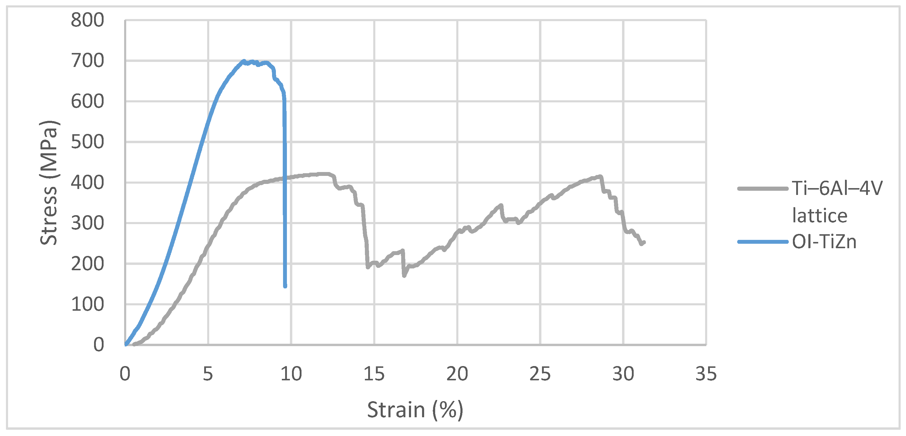
3.2. Mechanical Properties in Terms of Compression Strength

The mechanical properties of the Ti-base lattice and the OI–TiZn system along the XZ plane were evaluated in terms of compression tests. Typical stress-strain curves are shown in Figure 6, along with the statistical deviations of the mechanical properties as presented in Table 1. The nominal cross section area of the lattice was calculated using the following equation:
A L = V L / h L
where A L is the cross-section area of the lattice, h L is the height of the sample, and V L is the cylindrical volume of the specimen obtained by the following relation:
V L = W L / ρ
where W L is the weight of the specimen, and ρ is the density, taken as 4.4 g/ cm 3 [41].
The obtained results showed a repeated loss and recovery of strength by the Ti-alloy lattice that can be related to the collapsing of cells along XZ planes, as indicated by Maskery et al. [42]. In comparison, the stable strength performance of the OI–TiZn system with a naturally higher ultimate compressive strength (UCS) and yield strength compared to the Ti–base lattice is in line with the basic observations of Jiang et al. [10]. The failure mode of the Ti-base lattice shown in Figure 7a displays a layer-by-layer crushing due to shear deformation. Contrarily, the mode of failure of the OI–TiZn system (Figure 7b) was dominated by the infiltrated Zn–2%Fe alloy and resulted in pure shear fracture, while maintaining the important mechanical integrity of the OI–TiZn system. According to Jiang et al. [36], this type of fracture can be related to the critical resolved shear stress developed along the internal planes of the OI–TiZn system.

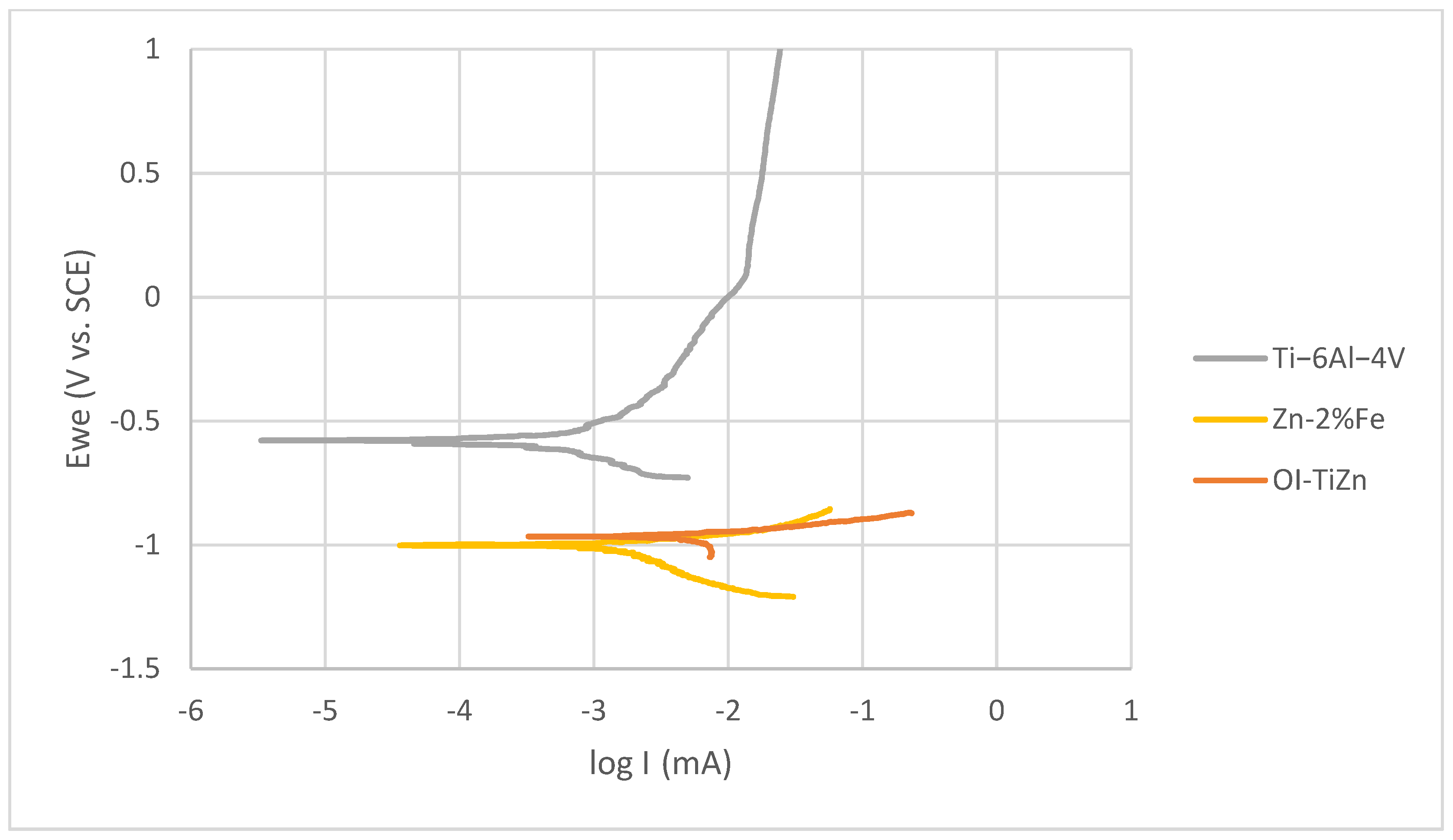
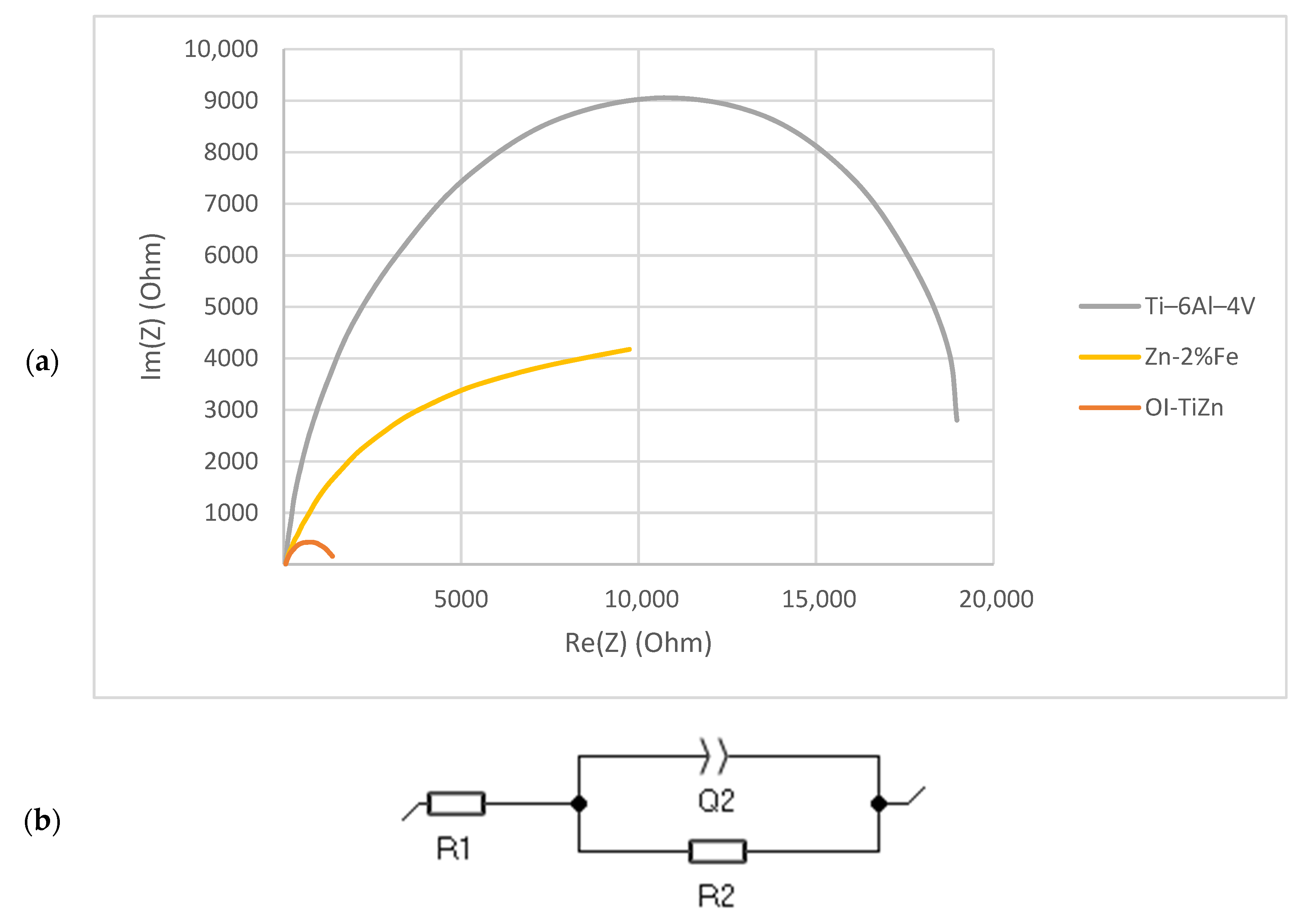
3.3. Corrosion Resistance and Electrochemical Behavior

The corrosion performance of the biodegradable Zn–2%Fe alloy and the OI–TiZn system under an immersion test in the PBS solution at 37 °C for 14 days is shown in Figure 8. This reveals that the corrosion rate of the OI–TiZn system was significantly higher, apparently due to the galvanic effect created between the Ti-base lattice and the infiltrated Zn–2%Fe alloy. This assumption was clearly supported by the general corrosion attack views shown in Figure 9, which demonstrate the increased corrosion attack at the boundary between the Ti-base rods and infiltrated alloy. A magnified view of this galvanic corrosion is shown in Figure 10. This noticeably reveals the significant degradation of the infiltrated Zn–2%Fe alloy, and the vicinity of the Ti-base lattice that was kept nearly intact in parallel.
An electrochemical analysis in terms of potentiodynamic polarization of Ti–6Al–4V alloy, biodegradable Zn–2%Fe alloy, and the OI–TiZn system is shown in Figure 11. This indicates that the polarization curve of the OI–TiZn system was shifted to higher current densities, indicating an increased corrosion rate [43]. This was supported by Tafel extrapolation (Table 2), which clearly revealed that the corrosion rate of the OI–TiZn system was higher by about three orders of magnitude as compared to the Ti-base lattice, and by less than two orders of magnitude as compared to the biodegradable Zn–2%Fe alloy. This electrochemical outcome clearly demonstrates the dominant effect of the infiltrated Zn–2%Fe alloy on corrosion tendencies of the OI–TiZn system. In addition, these results comply with the results obtained by the immersion tests, and the assumptions related to the substantial effects of galvanic corrosion.
A further investigation of the electrochemical behavior of the tested materials was carried out using EIS in terms of a Nyquist plot, as shown in Figure 12a. This clearly shows a significant reduction in the radii of curvature of the OI–TiZn system as compared to both Ti-base lattice and Zn–2%Fe alloy. According to Kafri et al. [18], the reduced radius of curvature is an indication of a reduced corrosion resistance. The electrical equivalent circuit fitted to the Nyquist plots is shown in Figure 12b, where R1 represents the solution resistance, R2 the specimen’s resistance, and Q2 the capacitor created by the double layer. The values derived from the plots in correlation with the electrical circuit are shown in Table 3. This indicates that the resistance R2 of the OI–TiZn system was reduced by one order of magnitude, as compared to that of the Ti-base lattice alloy and the Zn–2%Fe alloy. Altogether, the results of the EIS are in accord with the outcome obtained by the potentiodynamic polarization analysis and the immersion test.

3.4. Cytotoxicity Analysis

An indirect cytotoxicity analysis of the OI–TiZn system and the Ti–6Al–4V reference alloy that has excellent biocompatible properties [44] was carried out following incubation periods of 24 h and 48 h, as shown in Figure 13, in terms of cell viability. In the case of the OI–TiZn system, the dilution rate was 10% in order to rectify the natural buffering gap that exists between the in vivo and in vitro conditions [38,45]. The obtained results clearly indicate that both the Ti–6Al–4V alloy and the OI–TiZn system can be considered to be non-cytotoxic substrates for 4T1 cells due to a cell viability above 70%. These quantitative results comply with ISO-10993-5 (tests for in-vitro cytotoxicity) [46], which indicates that a viability reduction of up to 30% is not considered to be cytotoxic. The general appearance of the 4T1 cells after 48 h, as shown in Figure 14, complies with the quantitative analysis. The cells incubated in extracts of 10% OI–TiZn, Ti–6Al–4V alloy, and DMEM only, look normal and healthy.

4. Discussion

The attractiveness of an AM lattice infiltrated with a biodegradable alloy as a potential structural material for implants mainly relates to its capability to stimulate osseointegration bonding [2,3]. Furthermore, AM technologies enable the production of complex implants that can address, for example, special personal needs in dental and orthopedic operations. In the case of the OI–TiZn system, the potential osseointegration bonding can be implemented by the dissolution of the infiltrated biodegradable Zn–2%Fe alloy and, in parallel, the formation of bone tissue within the open space of the permanent Ti-base lattice implant. Other inherent advantages of OI–TiZn systems relate to the capability of Zinc to stimulate bone growth [29] and to act as an antibacterial substance that can prevent infections post-implantation.
The results obtained by this study in in vitro conditions clearly demonstrate the adequate bonding created between the biodegradable Zn–2%Fe alloy and the Ti-base lattice post-infiltration. This was naturally manifested by a significant increase in strength of the OI–TiZn system as compared to the monolithic lattice structure in terms of UCS—699 vs. 430 MPa, and yield strength—606 vs. 396 MPa. In addition, the fact that the mechanical integrity of the OI–TiZn was maintained following the compression test failure can also serve as an indication of the satisfactory bonding between the degradable alloy and the Ti lattice. The adequate matching between the infiltrated Zn–2%Fe alloy and the Ti-base lattice was also visible through the microstructure analysis. It is believed that the interface layer, with a width of about 130 µm that includes TiZn3 precipitates, is created by mutual diffusion between the infiltrated alloy and the Ti-base lattice. Consequently, this can contribute to the improved bonding between those two materials.
The corrosion rate of the OI–TiZn system in terms of the immersion test, potentiodynamic polarization, and EIS analysis in a simulated physiological solution was basically similar and within the range of about 0.15–1.6 mmpy. Although this was relatively increased as compared to the corrosion rate of the biodegradable Zn–2%Fe alloy (0.033 ± 0.75 mmpy) due to microgalvanic effects, this can be basically tolerated in in vivo conditions. In fact, according to Guillory et al. [33], arterial implants produced from pure Zn with corrosion rates of about 0.02–0.05 mmpy may provoke fibrous encapsulation that can isolate the implant and arrest the biodegradation process [47,48]. As a result, the relatively increased corrosion rate of the OI–TiZn system can be considered to be an inherent advantage that may prevent the potential danger of encapsulation processes in in vivo conditions. Furthermore, the prospects of the OI–TiZn system as an adequate implant material were also supported by the indirect cytotoxicity evaluation analysis in terms of cell viability. This clearly indicated that the OI–TiZn system can be related as a non-cytotoxic substance to relatively sensitive 4T1 cells. The average cells’ viability on the OI–TiZn system after 24 h and 48 h of incubation was 140% and 190%, respectively, which is well above the required cell viability of 70%. In addition, it was evident that the general appearance of the cells post-incubation was quite normal and healthy.

5. Conclusions

The in vitro results obtained by this study clearly demonstrate the prospects of an OI–TiZn system as an adequate structural material for implants that can potentially improve osseointegration bonding. This was illustrated by indirect cytotoxicity analysis in terms of cell viability, which showed that an OI–TiZn system can be related as a non-cytotoxic substance to relatively sensitive 4T1 cells. Although the corrosion rate of the OI–TiZn system in a simulated physiological solution was slightly increased due to microgalvanic effects, the obtained degradation rate can be considered to be quite tolerable. The adequate bonding obtained between the Ti-base lattice and the infiltrated Zn–2%Fe alloy was able to maintain the mechanical integrity of the OI–TiZn system under compression test conditions. This study should be followed by in vivo experiments that will demonstrate the capability of an OI–TiZn system to act as the structural material to enhance osseointegration.

Author Contributions

Conceptualization and design of the experiments: E.A., A.S. and N.G.; Writing: N.G. and E.A.; performed the experiments: N.G.; assisted with the experiments: T.R.; assisted with the experiments relating to cytotoxicity evaluation: R.V. All authors have read and agreed to the published version of the manuscript.

Funding

This research received no external funding.

Institutional Review Board Statement

Not applicable.

Informed Consent Statement

Not applicable.

Data Availability Statement

Data Sharing Not Applicable.

Conflicts of Interest

The authors declare no conflict of interest.

References

  1. Albrektsson, T.; Brånemark, P.-I.; Hansson, H.-A.; Lindström, J. Osseointegrated Titanium Implants: Requirements for Ensuring a Long-Lasting, Direct Bone-to-Implant Anchorage in Man. Acta Orthop. Scand. 1981, 52, 155–170. [Google Scholar] [CrossRef] [PubMed] [Green Version]
  2. Albrektsson, T.; Chrcanovic, B.; Jacobsson, M.; Wennerberg, A. Osseointegration of Implants—A Biological and Clinical Overview. JSM Dent. Surg. 2017, 2, 1022. [Google Scholar]
  3. Castellani, C.; Lindtner, R.A.; Hausbrandt, P.; Tschegg, E.; Stanzl-Tschegg, S.E.; Zanoni, G.; Beck, S.; Weinberg, A.-M. Bone–implant interface strength and osseointegration: Biodegradable magnesium alloy versus standard titanium control. Acta Biomater. 2011, 7, 432–440. [Google Scholar] [CrossRef] [PubMed]
  4. Kobryn, P.A.; Semiatin, S.L. Mechanical Properties of Laser-Deposited Ti-6Al-4V. In International Solid Freeform Fabrication Symposium; Wright-Patterson Air Force Base: Ohio, OH, USA, 2001. [Google Scholar]
  5. Murr, L.; Esquivel, E.; Quinones, S.; Gaytan, S.; Lopez, M.; Martinez, E.; Medina, F.; Hernandez, D.; Martinez, J.; Stafford, S.; et al. Microstructures and mechanical properties of electron beam-rapid manufactured Ti–6Al–4V biomedical prototypes compared to wrought Ti–6Al–4V. Mater. Charact. 2009, 60, 96–105. [Google Scholar] [CrossRef]
  6. Sing, S.L.; An, J.; Yeong, W.Y.; Wiria, F.E. Laser and electron-beam powder-bed additive manufacturing of metallic implants: A review on processes, materials and designs. J. Orthop. Res. 2016, 34, 369–385. [Google Scholar] [CrossRef]
  7. Beaman, J.; Bourell, D.L.; Seepersad, C.; Kovar, D. Additive Manufacturing Review—Early Past to Current Practice. J. Manuf. Sci. Eng. 2020, 142, 1–50. [Google Scholar] [CrossRef]
  8. Mahmoud, D.; Elbestawi, M.A. Lattice Structures and Functionally Graded Materials Applications in Additive Manufacturing of Orthopedic Implants: A Review. J. Manuf. Mater. Process. 2017, 1, 13. [Google Scholar] [CrossRef]
  9. Balog, M.; Snajdar, M.; Krizik, P.; Schauperl, Z.; Stanec, Z.; Catic, A. Titanium-Magnesium Composite for Dental Implants (BIACOM). In Proceedings of the International Conference on Martensitic Transformations, Chicago, IL, USA, 9–14 July 2017; pp. 271–284. [Google Scholar]
  10. Jiang, G.; Wang, C.; Li, Q.; Dong, J.; He, G. Porous titanium with entangled structure filled with biodegradable magnesium for potential biomedical applications. Mater. Sci. Eng. C 2015, 47, 142–149. [Google Scholar] [CrossRef] [PubMed]
  11. Bruni, S.; Martinesi, M.; Stio, M.; Treves, C.; Bacci, T.; Borgioli, F. Effects of surface treatment of Ti–6Al–4V titanium alloy on biocompatibility in cultured human umbilical vein endothelial cells. Acta Biomater. 2005, 1, 223–234. [Google Scholar] [CrossRef]
  12. Niinomi, M. Mechanical properties of biomedical titanium alloys. Mater. Sci. Eng. A 1998, 243, 231–236. [Google Scholar] [CrossRef]
  13. Liang, H.; Yang, Y.; Xie, D.; Li, L.; Mao, N.; Wang, C.J.; Tian, Z.; Jiang, Q.; Shen, L. Trabecular-like Ti-6Al-4V scaffolds for orthopedic: Fabrication by selective laser melting and in vitro biocompatibility. J. Mater. Sci. Technol. 2019, 35, 1284–1297. [Google Scholar] [CrossRef]
  14. Attar, H.; Ehtemam-Haghighi, S.; Soro, N.; Kent, D.; Dargusch, M.S. Additive manufacturing of low-cost porous titanium-based composites for biomedical applications: Advantages, challenges and opinion for future development. J. Alloys Compd. 2020, 827, 154263. [Google Scholar] [CrossRef]
  15. Jawed, S.; Rabadia, C.D.; Liu, Y.; Wang, L.; Qin, P.; Li, Y.; Zhang, X.; Zhang, L. Strengthening mechanism and corrosion resistance of beta-type Ti-Nb-Zr-Mn alloys. Mater. Sci. Eng. C 2020, 110, 110728. [Google Scholar] [CrossRef]
  16. Gudkov, S.V.; Simakin, A.V.; Sevostyanov, M.A.; Konushkin, S.V.; Losertová, M.; Ivannikov, A.Y.; Kolmakov, A.G.; Izmailov, A.Y. Manufacturing and Study of Mechanical Properties, Structure and Compatibility with Biological Objects of Plates and Wire from New Ti-25Nb-13Ta-5Zr Alloy. Metals 2020, 10, 1584. [Google Scholar] [CrossRef]
  17. Liang, C.; Zhao, J.; Chang, J.; Wang, H. Microstructure evolution and nano-hardness modulation of rapidly solidified Ti–Al–Nb alloy. J. Alloys Compd. 2020, 836, 155538. [Google Scholar] [CrossRef]
  18. Kafri, A.; Ovadia, S.; Goldman, J.; Drelich, J.; Aghion, E. The Suitability of Zn–1.3%Fe Alloy as a Biodegradable Implant Material. Metals 2018, 8, 153. [Google Scholar] [CrossRef] [Green Version]
  19. Zhao, D.; Brown, A.; Wang, T.; Yoshizawa, S.; Sfeir, C.; Heineman, W.R. In vivo quantification of hydrogen gas concentration in bone marrow surrounding magnesium fracture fixation hardware using an electrochemical hydrogen gas sensor. Acta Biomater. 2018, 73, 559–566. [Google Scholar] [CrossRef] [PubMed]
  20. Zhao, D.; Wang, T.; Kuhlmann, J.; Dong, Z.; Chen, S.; Joshi, M.; Salunke, P.; Shanov, V.N.; Hong, D.; Kumta, P.N.; et al. In vivo monitoring the biodegradation of magnesium alloys with an electrochemical H2 sensor. Acta Biomater. 2016, 36, 361–368. [Google Scholar] [CrossRef] [PubMed] [Green Version]
  21. Aghion, E.; Gueta, Y.; Moscovitch, N.; Bronfin, B. Effect of yttrium additions on the properties of grain-refined Mg–3%Nd alloy. J. Mater. Sci. 2008, 43, 4870–4875. [Google Scholar] [CrossRef]
  22. Aghion, E.; Bronfin, B.; Eliezer, D.; Von Buch, F.; Schumann, S.; Friedrich, H.E. The Art of Developing New Magnesium Alloys for High Temperature Applications. Mater. Sci. Forum 2003, 419–422, 407–418. [Google Scholar] [CrossRef]
  23. Levy, G.K.; Kafri, A.; Ventura, Y.; Leon, A.; Vago, R.; Goldman, J.; Aghion, E. Surface stabilization treatment enhances initial cell viability and adhesion for biodegradable zinc alloys. Mater. Lett. 2019, 248, 130–133. [Google Scholar] [CrossRef]
  24. Kabir, H.; Munir, K.; Wen, C.; Li, Y. Recent research and progress of biodegradable zinc alloys and composites for biomedical applications: Biomechanical and biocorrosion perspectives. Bioact. Mater. 2021, 6, 836–879. [Google Scholar] [CrossRef]
  25. Li, H.F.; Xie, X.H.; Zheng, Y.F.; Cong, Y.; Zhou, F.Y.; Qiu, K.J.; Wang, X.; Chen, S.H.; Huang, L.; Tian, L.; et al. Development of biodegradable Zn-1X binary alloys with nutrient alloying elements Mg, Ca and Sr. Sci. Rep. 2015, 5, srep10719. [Google Scholar] [CrossRef]
  26. Sikora-Jasinska, M.; Mostaed, E.; Beanland, R.; Mantovani, D.; Vedani, M. Fabrication, mechanical properties and in vitro degradation behavior of newly developed Zn Ag alloys for degradable implant applications. Mater. Sci. Eng. C 2017, 77, 1170–1181. [Google Scholar] [CrossRef]
  27. Lin, S.; Wang, Q.; Yan, X.; Ran, X.; Wang, L.; Zhou, J.G.; Hu, T.; Wang, G. Mechanical properties, degradation behaviors and biocompatibility evaluation of a biodegradable Zn-Mg-Cu alloy for cardiovascular implants. Mater. Lett. 2019, 234, 294–297. [Google Scholar] [CrossRef]
  28. Tong, X.; Zhang, D.; Zhang, X.; Su, Y.; Shi, Z.; Wang, K.; Lin, J.; Li, Y.; Lin, J.; Wen, C. Microstructure, mechanical properties, biocompatibility, and in vitro corrosion and degradation behavior of a new Zn–5Ge alloy for biodegradable implant materials. Acta Biomater. 2018, 82, 197–204. [Google Scholar] [CrossRef] [PubMed]
  29. Ceylan, M.N.; Akdas, S.; Yazihan, N. Is Zinc an Important Trace Element on Bone-Related Diseases and Complications? A Meta-analysis and Systematic Review from Serum Level, Dietary Intake, and Supplementation Aspects. Biol. Trace Elem. Res. 2021, 199, 535–549. [Google Scholar] [CrossRef] [PubMed]
  30. Rink, L.; Gabriel, P. Zinc and the immune system. Proc. Nutr. Soc. 2000, 59, 541–552. [Google Scholar] [CrossRef] [PubMed] [Green Version]
  31. Roselli, M.; Finamore, A.; Britti, M.S.; Bosi, P.; Oswald, I.; Mengheri, E. Alternatives to in-feed antibiotics in pigs: Evaluation of probiotics, zinc or organic acids as protective agents for the intestinal mucosa. A comparison of in vitro and in vivo results. Anim. Res. 2005, 54, 203–218. [Google Scholar] [CrossRef]
  32. Ibs, K.-H.; Rink, L. Zinc-Altered Immune function. J. Nutr. 2003, 133, 1452S–1456S. [Google Scholar] [CrossRef]
  33. Guillory, R.J.; Bowen, P.K.; Hopkins, S.P.; Shearier, E.R.; Earley, E.J.; Gillette, A.A.; Aghion, E.; Bocks, M.L.; Drelich, J.W.; Goldman, J. Corrosion Characteristics Dictate the Long-Term Inflammatory Profile of Degradable Zinc Arterial Implants. ACS Biomater. Sci. Eng. 2016, 2, 2355–2364. [Google Scholar] [CrossRef]
  34. Kafri, A.; Ovadia, S.; Yosafovich-Doitch, G.; Aghion, E. The Effects of 4%Fe on the Performance of Pure Zinc as Biodegradable Implant Material. Ann. Biomed. Eng. 2019, 47, 1400–1408. [Google Scholar] [CrossRef]
  35. Kaya, A.; Uzan, P.; Eliezer, D.; Aghion, E. Electron microscopical investigation of as cast AZ91D alloy. Mater. Sci. Technol. 2000, 16, 1001–1006. [Google Scholar] [CrossRef]
  36. Jiang, G.; Li, Q.; Wang, C.; Dong, J.; He, G. Fabrication of graded porous titanium–magnesium composite for load-bearing biomedical applications. Mater. Des. 2015, 67, 354–359. [Google Scholar] [CrossRef]
  37. Buchanan, R.A.; Stansbury, E.E. Electrochemical Corrosion. In Handbook of Environmental Degradation of Materials, 2nd ed.; Kutz, M., Ed.; William Andrew Publishing: Norwich, NY, USA, 2012; pp. 87–125. [Google Scholar]
  38. Wang, J.; Witte, F.; Xi, T.; Zheng, Y.; Yang, K.; Yang, Y.; Zhao, D.; Meng, J.; Li, Y.; Li, W.; et al. Recommendation for modifying current cytotoxicity testing standards for biodegradable magnesium-based materials. Acta Biomater. 2015, 21, 237–249. [Google Scholar] [CrossRef] [PubMed]
  39. Li, P.; Schille, C.; Schweizer, E.; Rupp, F.; Heiss, A.; Legner, C.; Klotz, U.E.; Geis-Gerstorfer, J.; Scheideler, L. Mechanical Characteristics, In Vitro Degradation, Cytotoxicity, and Antibacterial Evaluation of Zn-4.0Ag Alloy as a Biodegradable Material. Int. J. Mol. Sci. 2018, 19, 755. [Google Scholar] [CrossRef] [Green Version]
  40. Raghavan, V. Fe-Ti-Zn (Iron-Titanium-Zinc). J. Phase Equilibria Diffus. 2008, 29, 458. [Google Scholar] [CrossRef]
  41. Qian, M.; Xu, W.; Brandt, M.; Tang, H. Additive manufacturing and postprocessing of Ti-6Al-4V for superior mechanical properties. MRS Bull. 2016, 41, 775–784. [Google Scholar] [CrossRef] [Green Version]
  42. Maskery, I.; Aboulkhair, N.T.; Aremu, A.; Tuck, C.; Ashcroft, I. Compressive failure modes and energy absorption in additively manufactured double gyroid lattices. Addit. Manuf. 2017, 16, 24–29. [Google Scholar] [CrossRef]
  43. Itzhak, D.; Aghion, E. An anodic behaviour study of an analogical sintered system of austenitic stainless steel in H2SO4 solution. Corros. Sci. 1984, 24, 145–149. [Google Scholar] [CrossRef]
  44. Dong, Y.; Tang, J.; Wang, D.; Wang, N.; He, Z.; Li, J.; Zhao, D.; Yan, M. Additive manufacturing of pure Ti with superior mechanical performance, low cost, and biocompatibility for potential replacement of Ti-6Al-4V. Mater. Des. 2020, 196, 109142. [Google Scholar] [CrossRef]
  45. Hong, D.; Saha, P.; Chou, D.-T.; Lee, B.; Collins, B.E.; Tan, Z.; Dong, Z.; Kumta, P.N. In vitro degradation and cytotoxicity response of Mg–4% Zn–0.5% Zr (ZK40) alloy as a potential biodegradable material. Acta Biomater. 2013, 9, 8534–8547. [Google Scholar] [CrossRef] [PubMed]
  46. ISO. ISO-10993-5 Biological Evaluation of Medical Devices, Part 5: Tests for In Vitro Cytotoxicity; ISO Central Secretaria: Geneva, Switzerland, 2009. [Google Scholar]
  47. Tjellström, A.; Rosenhall, U.; Lindström, J.; Hallén, O.; Albrektsson, T.; Brånemark, P.I. Five-Year Experience with Skin-Penetrating Bone-Anchored Implants in the Temporal Bone. Acta Oto-Laryngol. 1983, 95, 568–575. [Google Scholar] [CrossRef] [PubMed]
  48. Geetha, M.; Singh, A.K.; Asokamani, R.; Gogia, A.K. Ti based biomaterials, the ultimate choice for orthopaedic implants—A review. Prog. Mater. Sci. 2009, 54, 397–425. [Google Scholar] [CrossRef]
Figure 1. (a,b) General and close-up views of Ti-base lattice and infiltrated lattice (OI–TiZn system), respectively.
Materials 14 04682 g001
Figure 2. General appearance of the boundary between the Ti–6Al–4V lattice and the infiltrated Zn–2%Fe alloy: (a) close-up view and (b) magnified view of the interface layer between the two alloys.
Materials 14 04682 g002
Figure 3. Chemical composition of the interface layer between the Ti-base lattice and infiltrated Zn–2%Fe alloy—(a) line scan direction and (b) chemical composition obtained by EDS analysis.
Materials 14 04682 g003
Figure 4. Spot chemical composition measurements along the border obtained by EDS analysis with an error of 2%at.
Materials 14 04682 g004
Figure 5. XRD analysis of (a) Ti–6Al–4V lattice, (b) Zn–2%Fe alloy, and (c) mixed powder of OI–TiZn system without the intact Ti-base lattice rods.
Materials 14 04682 g005
Figure 6. Typical compressive stress-strain curves of Ti–6Al–4V lattice and OI–TiZn system.
Materials 14 04682 g006
Figure 7. Typical mode of failure obtained under compression stress of (a) Ti–6Al–4V lattice, (b) OI–TiZn system.
Materials 14 04682 g007
Figure 8. Corrosion rate measurements obtained after immersion tests of Zn–2%Fe alloy and OI–TiZn system in PBS solution at 37 °C for 14 days.
Materials 14 04682 g008
Figure 9. General appearance of corrosion attack obtained after 14 days of immersion test: (a) Zn–2%Fe alloy and (b) OI–TiZn system.
Materials 14 04682 g009
Figure 10. A magnified view of the galvanic corrosion attack in the vicinity of the Ti-base lattice after immersion test for 14 days.
Materials 14 04682 g010
Figure 11. Potentiodynamic polarization analysis of Ti–6Al–4V lattice, Zn–2%Fe alloy, and OI–TiZn system in PBS solution.
Materials 14 04682 g011
Figure 12. (a) Nyquist plots of Ti-base lattice, Zn–2%Fe alloy, and OI–TiZn system; (b) fitted electrical equivalent circuit (EEC).
Materials 14 04682 g012
Figure 13. Viability analysis of 4T1 cells in terms of their metabolic activity after incubation of 24 h and 48 h in extracts of the tested materials.
Materials 14 04682 g013
Figure 14. General appearance of 4T1 cells after 48 h incubation in extracts of: (a) Ti–6Al–4V alloy, (b) 10% OI–TiZn, (c) DMEM, and (d) 10% DMSO.
Materials 14 04682 g014
Table 1. Statistical deviations of the mechanical properties under compressive loading of Ti-base lattice and OI–TiZn system.
Ultimate Compressive Strength (UCS) (MPa)Yield Point (MPa)
Ti–6Al–4V lattice429.9 ± 6.3397.9 ± 2.6
OI–TiZn system699 ± 120606 ± 53
Table 2. The results obtained by Tafel extrapolation including statistical deviations.
Ti–6Al–4VZn–2%FeOI–TiZn
E corr ( V ¯ )   vs .   SCE −0.52 ± 0.06−1.03 ± 0.05−0.965 ± 0.001
I corr ( μ A ) 0.80 ± 0.272.22 ± 2.059.95 ± 0.26
Corrosion Rate (mmpy)0.005 ± 0.0020.033 ± 0.0310.149 ± 0.004
Table 3. The electrical equivalent circuit parameters fitted from the Nyquist plots.
Ti–6Al–4VZn–2%FeOI–TiZn
R1 (Ω)48.2 ± 2.749.0 ± 1.075.9 ± 24.1
R2 (Ω)21,106 ± 427610,031 ± 19631182 ± 167
Q2 (μF)47 ± 4137 ± 6585 ± 7
Publisher’s Note: MDPI stays neutral with regard to jurisdictional claims in published maps and institutional affiliations.

