
Production of Hybrid Joints by Selective Laser Melting of Maraging Tool Steel 1.2709 on Conventionally Produced Parts of the Same Steel


Abstract
:1. Introduction
2. Materials and Methods
2.1. Materials
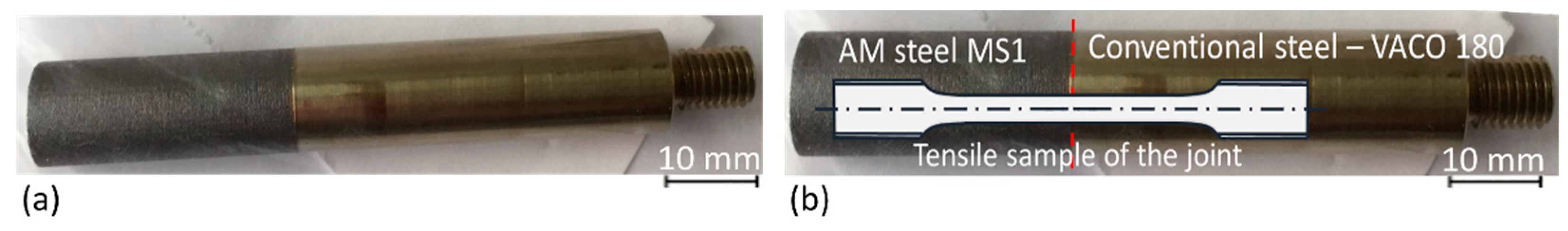
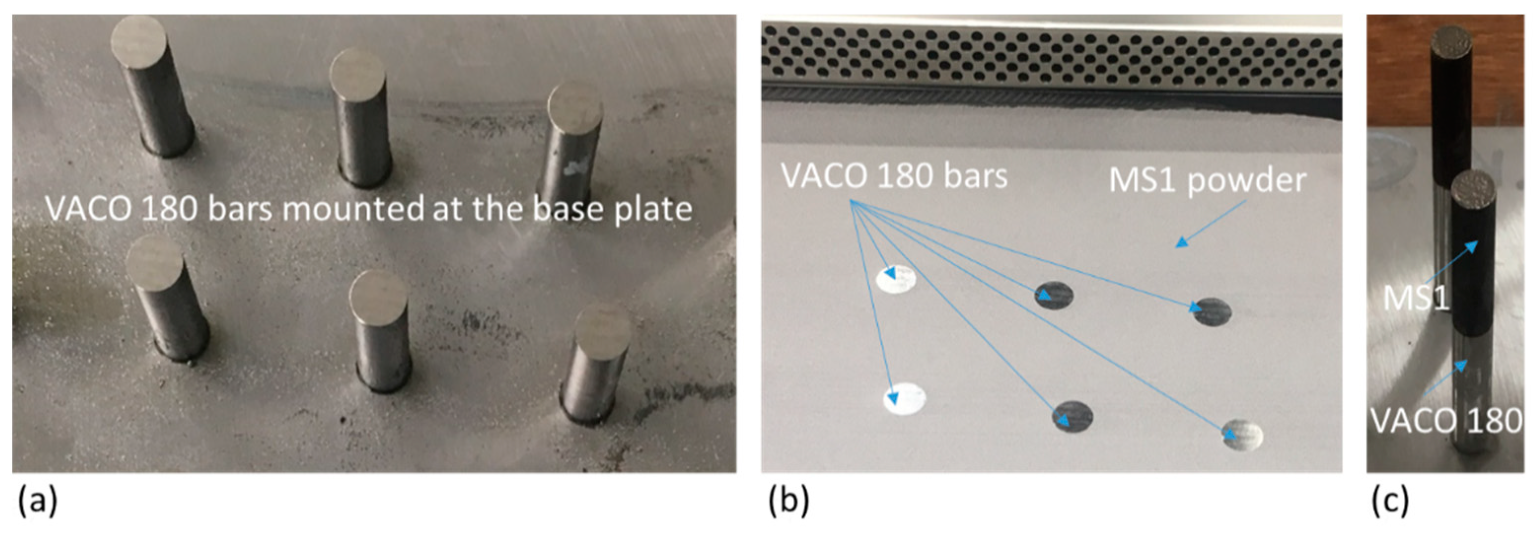
2.2. Additive Manufacturing
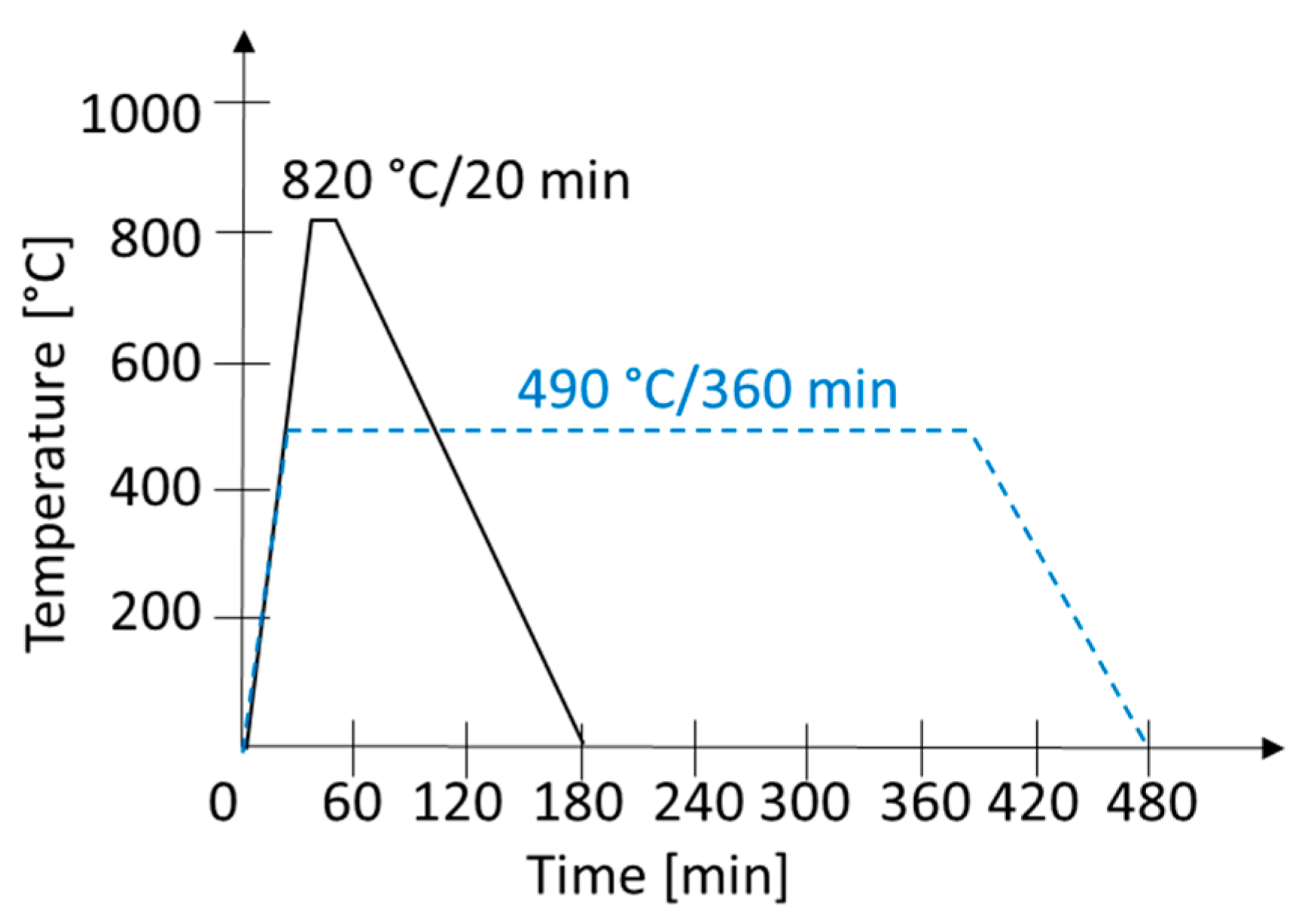
2.3. Heat Treatment
2.4. Characterisation
3. Results and Discussion
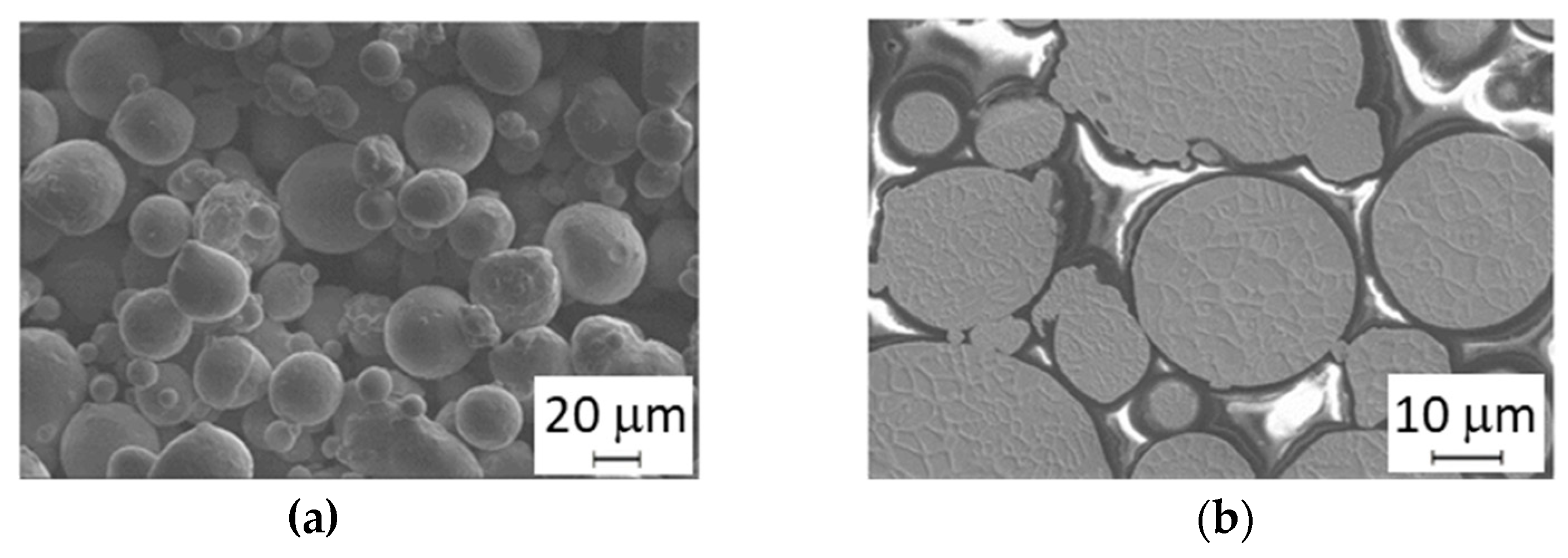
3.1. Microstructure Analysis of the Powder
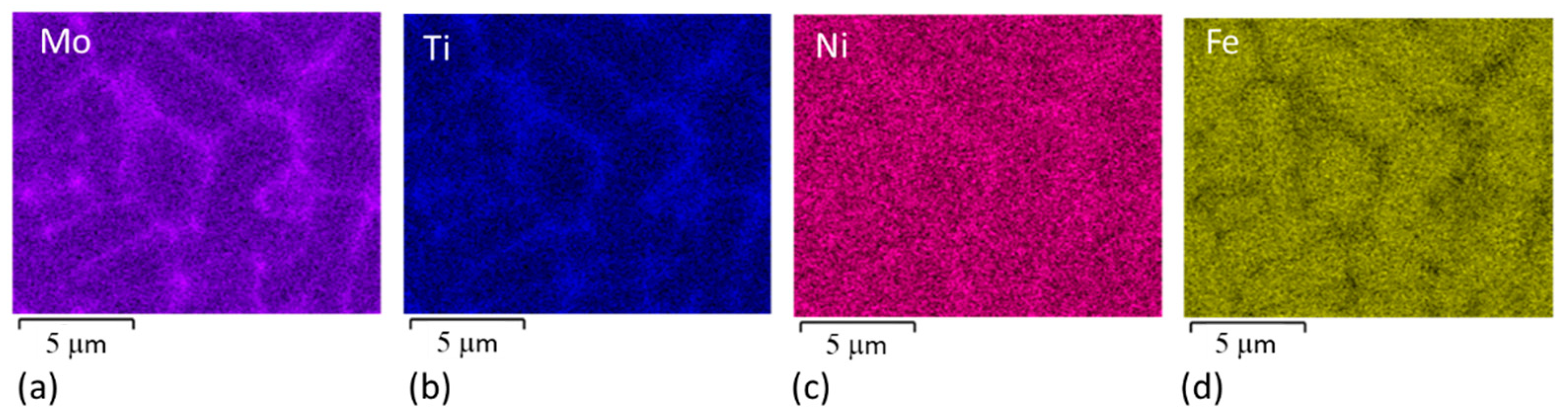
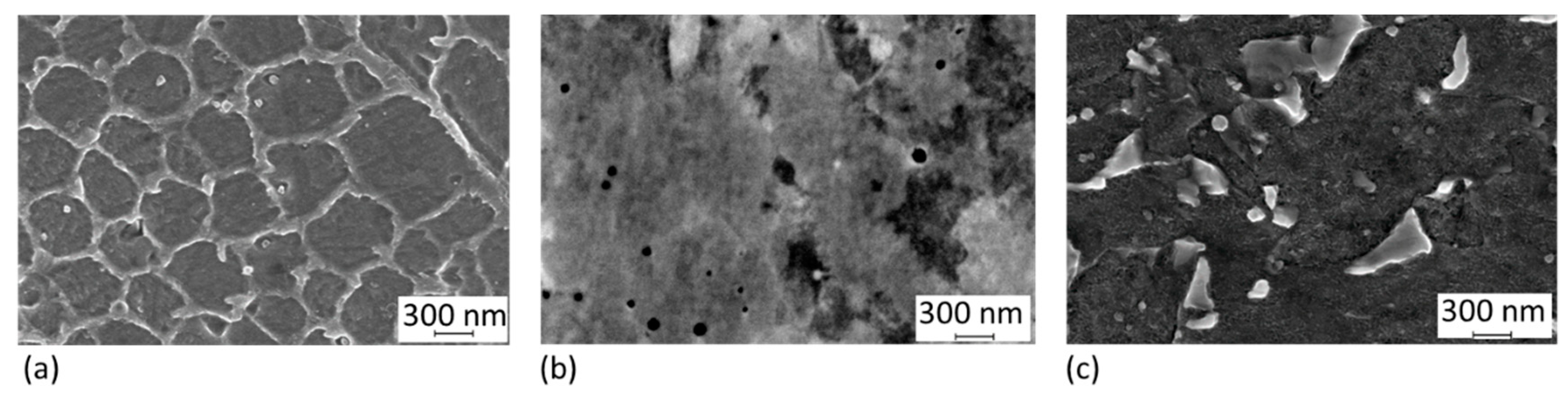
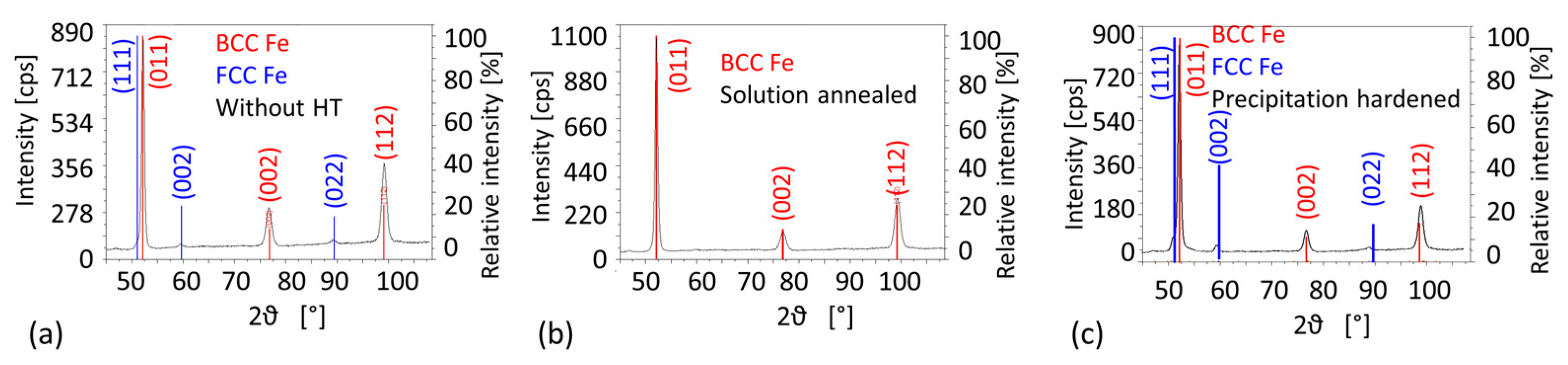
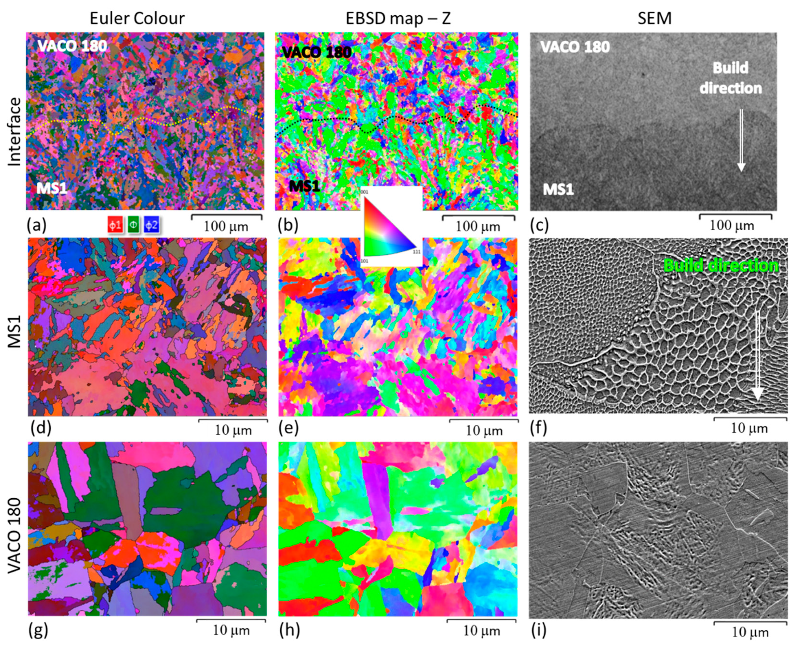
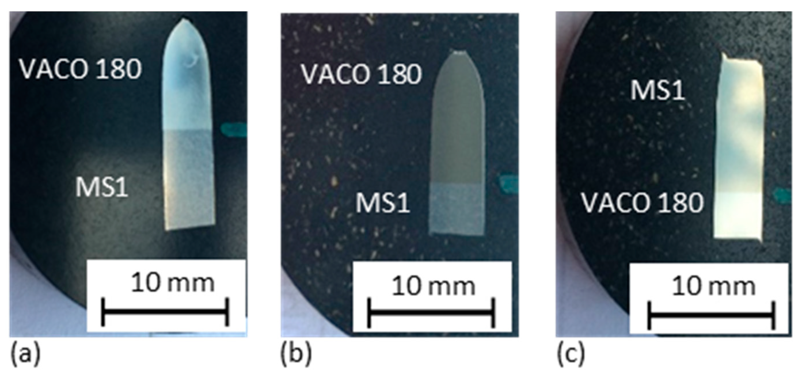
3.2. Microstructure Analysis of Hybrid Parts
3.3. Mechanical Properties
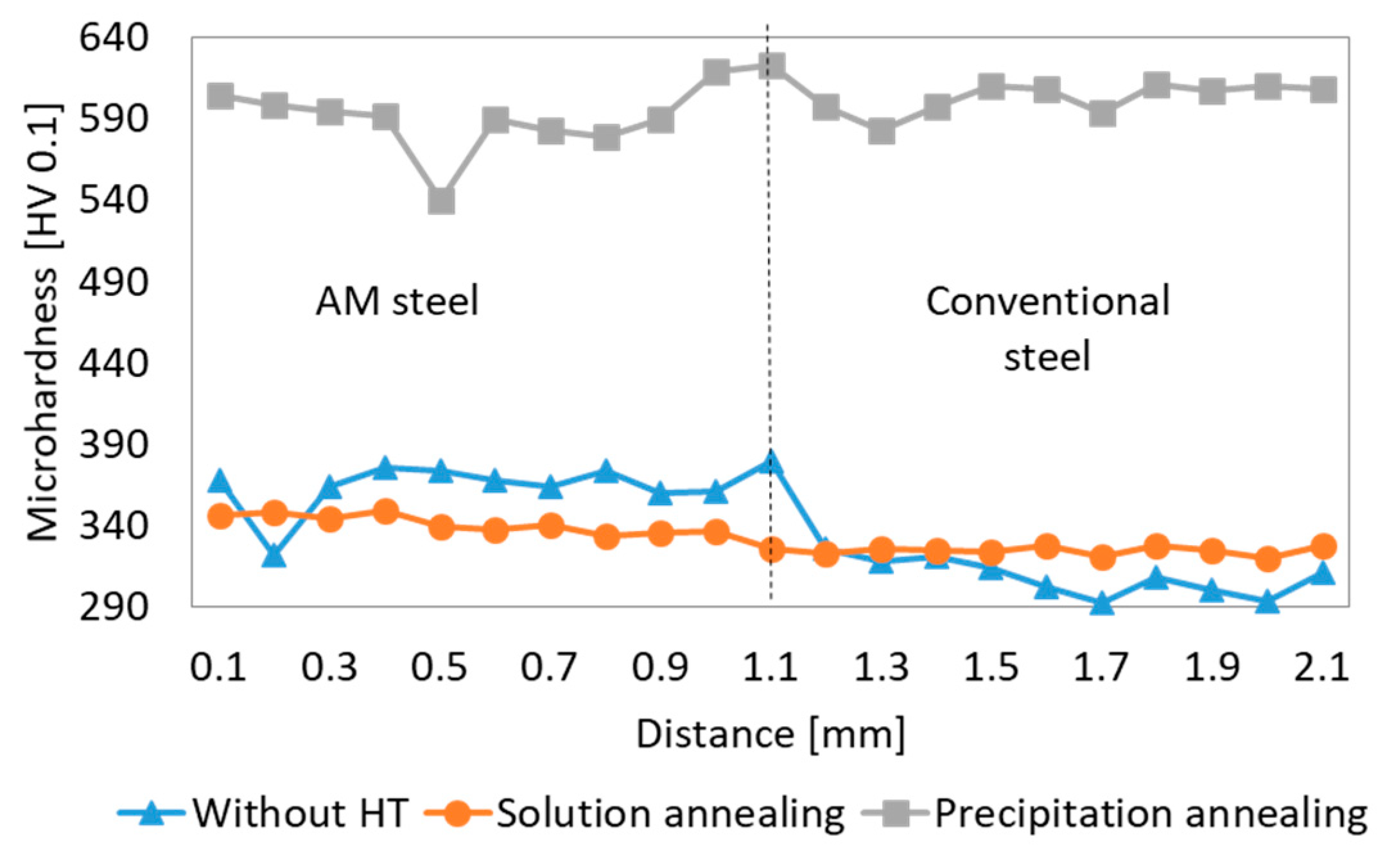
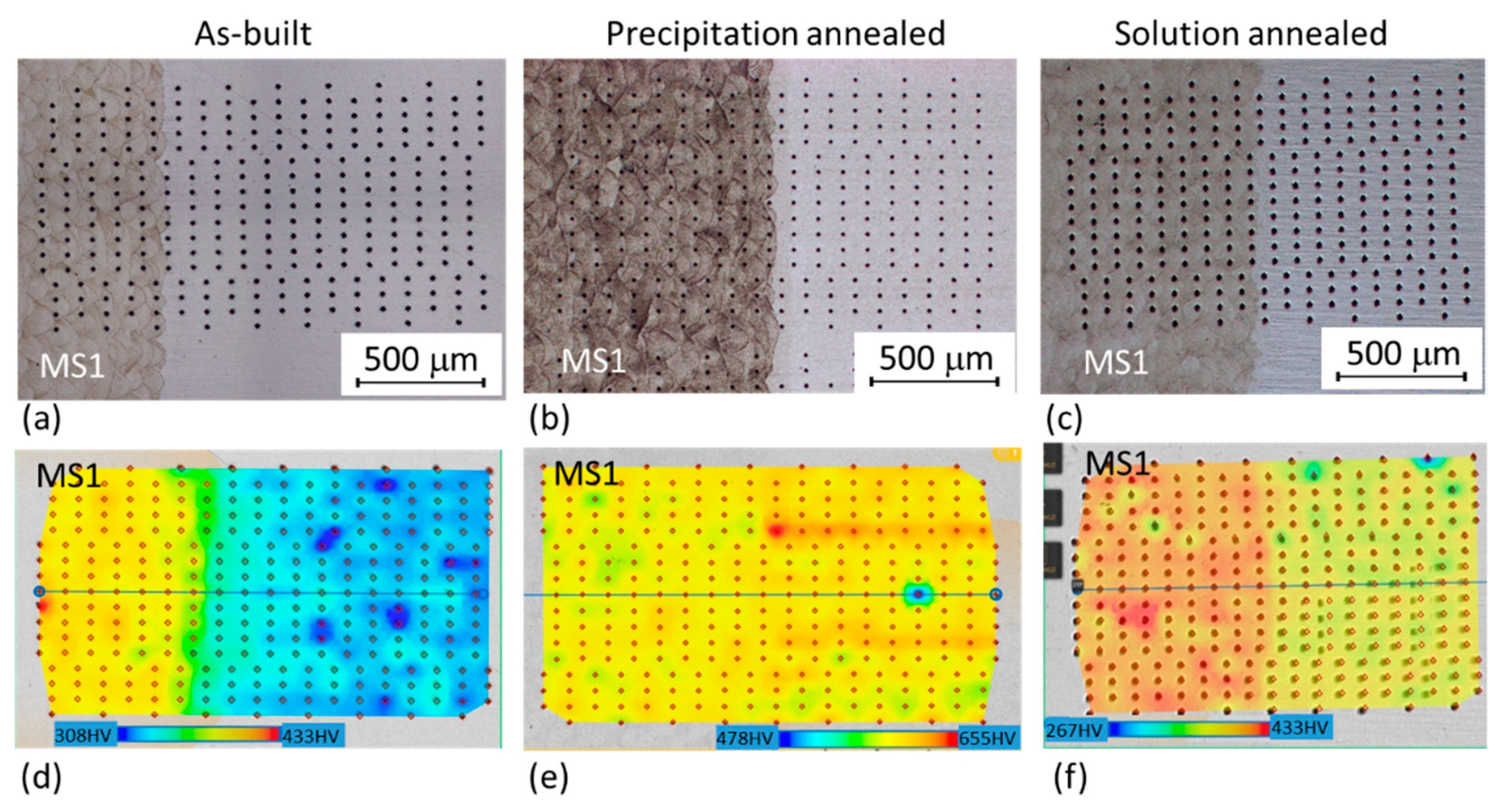
3.3.1. Hardness
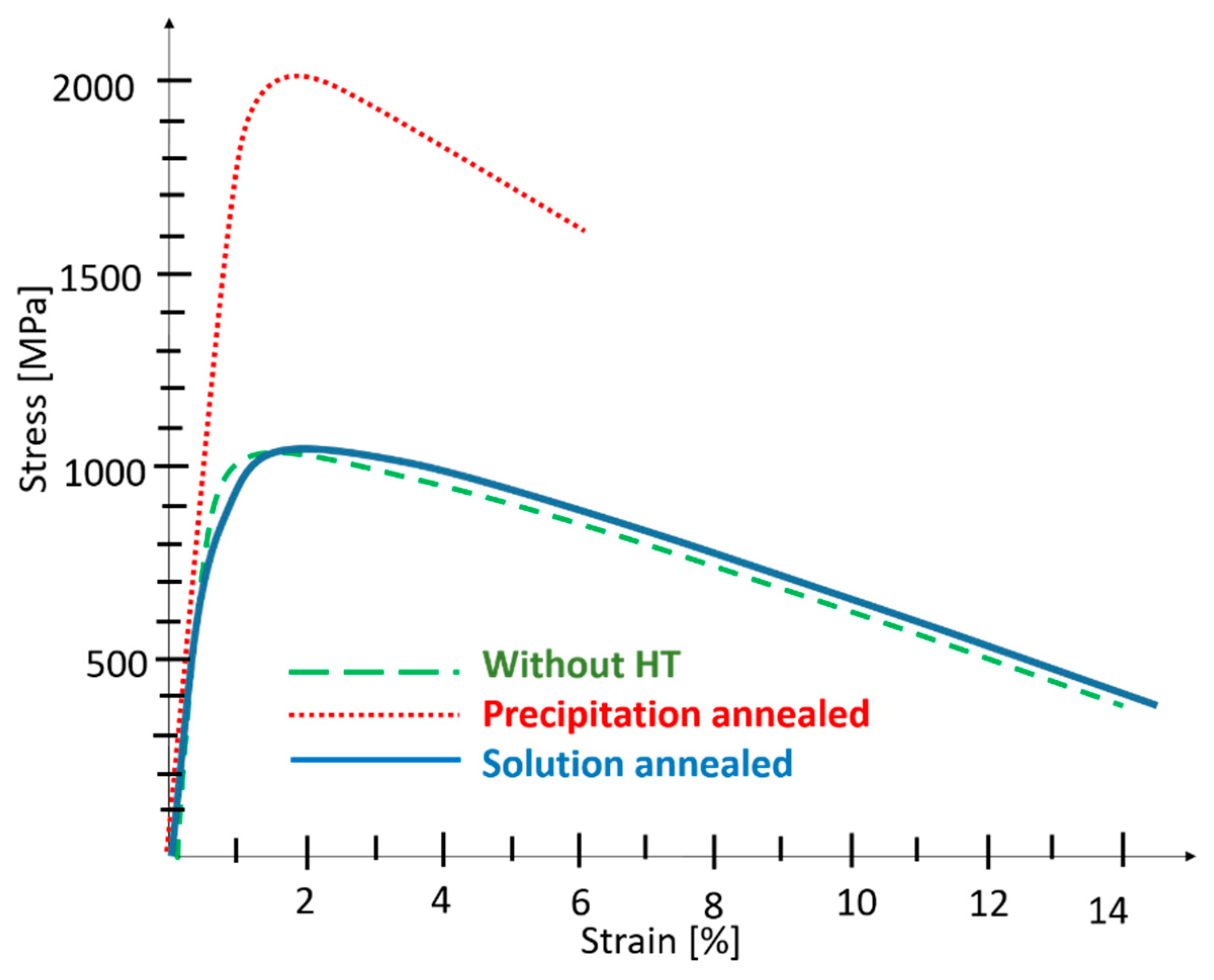
3.3.2. Tensile Test
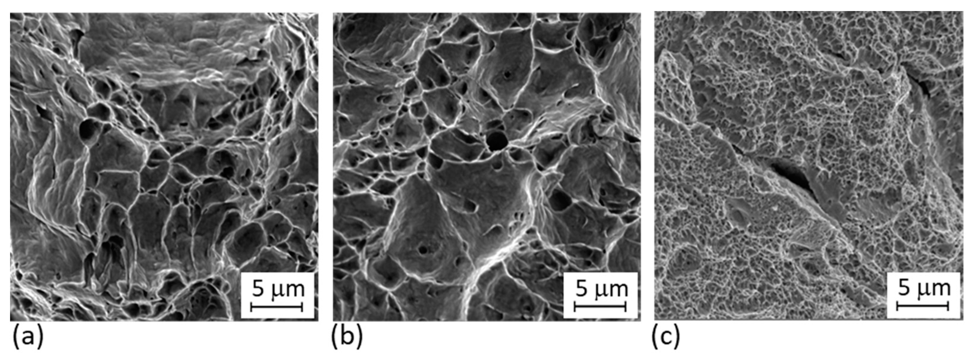
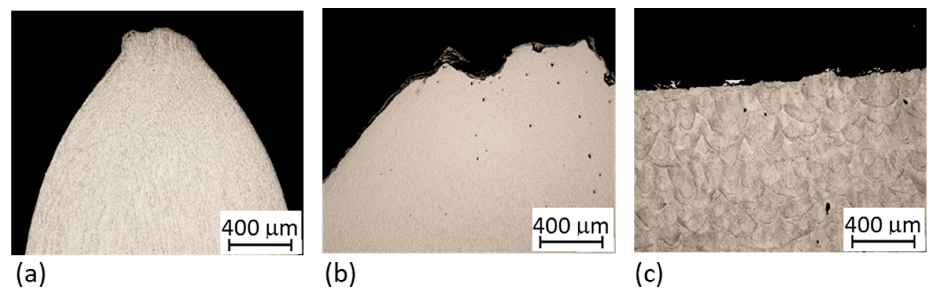
3.3.3. Fracture Analysis
4. Conclusions
Author Contributions
Funding
Institutional Review Board Statement
Informed Consent Statement
Data Availability Statement
Conflicts of Interest
References
- Li, N.; Huang, S.; Zhang, G.; Qin, R.; Liu, W.; Xiong, H.; Shi, G.; Blackburn, J. Progress in additive manufacturing on new materials: A review. J. Mater. Sci. Technol. 2019, 35, 242–269. [Google Scholar] [CrossRef]
- Ngo, T.D.; Kashani, A.; Imbalzano, G.; Nguyen, K.T.; Hui, D. Additive manufacturing (3D printing): A review of materials, methods, applications and challenges. Compos. B Eng. 2018, 143, 172–196. [Google Scholar] [CrossRef]
- Bourell, D.; Kruth, J.P.; Leu, M.; Levy, G.; Rosen, D.; Beese, A.M.; Clare, A. Materials for additive manufacturing. CIRP Ann. Manuf. Technol. 2017, 66, 659–681. [Google Scholar] [CrossRef]
- Faludi, J.; Van Sice, C.M.; Shi, Y.; Bower, J.; Brooks, O.M.K. Novel materials can radically improve whole-system environmental impacts of additive manufacturing. J. Clean. Prod. 2019, 212, 1580–1590. [Google Scholar] [CrossRef]
- Al Mangour, B.; Yang, J.M. Improving the surface quality and mechanical properties by shot-peening of 17–4 stainless steel fabricated by additive manufacturing. Mater. Des. 2016, 110, 914–924. [Google Scholar] [CrossRef]
- Kučerová, L.; Zetková, I.; Jeníček, Š.; Burdová, K. Hybrid parts produced by deposition of 18Ni300 maraging steel via selective laser melting on forged and heat treated advanced high strength steel. Addit. Manuf. 2020, 32, 101108. [Google Scholar] [CrossRef]
- Azizi, H.; Ghiaasiaan, R.; Prager, R.; Ghoncheh, M.H.; Samk, K.A.; Lausic, A.; Byleveld, W.; Phillion, A.B. Metallurgical and mechanical assessment of hybrid additively-manufactured maraging tool steels via selective laser melting. Addit. Manuf. 2019, 27, 389–397. [Google Scholar] [CrossRef]
- Cyr, E.; Asgari, H.; Shamsdini, S.; Purdy, M.; Hosseinkhani, K.; Mohammadi, M. Fracture behaviour of additively manufactured MS1-H13 hybrid hard steels. Mater. Lett. 2018, 212, 174–177. [Google Scholar] [CrossRef]
- Santos, L.M.S.; Jesus, J.; Ferreirea, J.M.; Costa, J.D.; Capela, C. Fracture toughness of hybrid components with selective laser melting 18Ni300 steel parts. Appl. Sci. 2018, 8, 1879. [Google Scholar] [CrossRef] [Green Version]
- Hur, J.; Lee, K.; Kim, J. Hybrid rapid prototyping system using machining and deposition. Comput. Aided Des. 2002, 34, 741–754. [Google Scholar] [CrossRef]
- Stavropoulos, P.; Foteinopoulos, P.; Papacharalampopoulos, A.; Bikas, H. Addressing the challenges for the industrial application of additive manufacturing: Towards a hybrid solution. Int. J. Lightweight Mater. Manuf. 2018, 1, 157–168. [Google Scholar] [CrossRef]
- Du, W.; Bai, Q.; Zhang, B. A Novel Method for Additive/Subtractive Hybrid Manufacturing of Metallic Parts. Procedia Manuf. 2016, 5, 1018–1030. [Google Scholar] [CrossRef] [Green Version]
- Bambach, M.D.; Bambach, M.; Sviridov, A.; Weiss, S. New process chains involving additive manufacturing and metal forming —A chance for saving energy? Procedia Eng. 2017, 207, 1176–1181. [Google Scholar] [CrossRef]
- Kučerová, L.; Zetková, I.; Jandová, A.; Bystrianský, M. Microstructural characterisation and in-situ straining of additive-manufactured X3NiCoMoTi 18-9-5 maraging steel. Mater. Sci. Eng. A 2019, 750, 80–90. [Google Scholar] [CrossRef]
- Kempen, K.; Yasa, E.; Thijs, L.; Kruth, J.P.; Van Humbeeck, J. Microstructure and mechanical properties of Selective Laser Melted 18Ni-300 steel. Phys. Procedia 2011, 12, 255–263. [Google Scholar] [CrossRef] [Green Version]
- Simm, T.H.; Sun, L.; Galvin, D.R.; Hill, P.; Rawson, M.; Birosca, S.; Gilbert, E.P.; Bhadeshia, H.; Perkins, K. The effect of a two-stage heat-treatment on the microstructural and mechanical properties of a maraging steel. Materials 2017, 10, 1346. [Google Scholar] [CrossRef] [Green Version]
- Monkova, K.; Zetkova, I.; Kučerová, L.; Zetek, M.; Monka, P.; Daňa, M. Study of 3D printing direction and effects of heat treatment on mechanical properties of MS1 maraging steel. Arch. Appl. Mech. 2019, 89, 791–804. [Google Scholar] [CrossRef]
- Bai, Y.; Yang, Y.; Wang, D.; Zhang, M. Influence mechanism of parameters process and mechanical properties evolution mechanism of maraging steel 300 by selective laser melting. Mater. Sci. Eng. A 2017, 703, 116–123. [Google Scholar] [CrossRef]
- Mutua, J.; Nakata, S.; Onda, T.; Chen, Z.C. Optimization of selective laser melting parameters and influence of post heat treatment on microstructure and mechanical properties of maraging steel. Mater. Des. 2017, 139, 486–497. [Google Scholar] [CrossRef]
- Kučerová, L.; Zetková, I. Metallography of 3D printed 1.2709 tool steel. Manuf. Technol. 2016, 16, 140–144. [Google Scholar] [CrossRef]
- Kürnsteiner, P.; Wilms, M.B.; Weisheit, A.; Barriobero-Vila, P.; Gault, B.; Jägle, E.A.; Raabe, D. In-process precipitation during laser additive manufacturing investigated by atom probe tomography. Microsc. Microanal. 2017, 23, 694–695. [Google Scholar] [CrossRef] [Green Version]
- Tan, C.; Zhou, K.; Ma, W.; Zhang, P.; Liu, M.; Kuang, T. Microstructural evolution, nanoprecipitation behavior and mechanical properties of selective laser melted high-performance grade 300 maraging steel. Mater. Des. 2017, 134, 23–34. [Google Scholar] [CrossRef]
- Antretter, T.; Fischer, F.D.; Cihak, U.; Tanaka, K.; Cailletaud, G.; Fratzl, P.; Ortner, B. Transformation Induced Plasticity (Trip) in a maraging steel. In IUTAM Symposium on Mechanics of Martensitic Phase Transformation in Solids. Solid Mechanics and Its Applications; Sun, Q.P., Ed.; Springer: Dordrecht, The Netherlands, 2002; Volume 101. [Google Scholar] [CrossRef]
- Mooney, B.; Kourousis, K.I.; Raghavendra, R. Plastic anisotropy of additively manufactured maraging steel: Influence of the build orientation and heat treatments. Addit. Manuf. 2019, 25, 19–31. [Google Scholar] [CrossRef] [Green Version]
- Luo, C.; Zhang, Y. Fusion zone characterization of resistance spot welded maraging steels via selective laser melting. J. Mater. Process. Tech. 2019, 273, 11653. [Google Scholar] [CrossRef]
- EN ISO 6892-1. Metallic Materials—Tensile Testing—Part 1: Method of Test at Room Temperature; International Organization for Standardization (ISO): Geneva, Switzerland, 2019. [Google Scholar]
- Opatová, K.; Zetková, I.; Kučerová, L. Relationship between the size and inner structure of particles of virgin and re-used MS1 rinmaraging steel powder for additive manufactug. Materials 2020, 13, 956. [Google Scholar] [CrossRef] [PubMed] [Green Version]
- Kučerová, L.; Burdová, K.; Jeníček, Š.; Chena, I. Effect of solution annealing and precipitation hardening at 250 °C–550 °C on microstructure and mechanical properties of additively manufactured 1.2709 maraging steel. Mater. Sci. Eng. A 2021, 814, 141195. [Google Scholar] [CrossRef]
- Sakai, P.R.; Lima MS, F.; Fanton, L.; Gomes, C.V.; Lombardo, S.; Silva, D.F.; Abdalla, A.J. Comparison of mechanical and microstructural characteristics in maraging 300 steel welded by three different processes: LASER. PLASMA and TIG. Procedia Eng. 2015, 114, 291–297. [Google Scholar] [CrossRef] [Green Version]
- Jägle, E.A.; Sheng, Z.; Kürnsteiner, P.; Ocylok, S.; Weisheit, A.; Raabe, D. Comparison of maraging steel micro- and nanostructure produced conventionally and by laser additive manufacturing. Materials 2017, 10, 8. [Google Scholar] [CrossRef] [Green Version]
- Fanton, L.; Abdalla, A.J.; de Lima, M.S.F. Heat treatment and Yb-Fiber laser welding of a maraging steel. Weld. J. 2014, 93, 326–368. [Google Scholar]
- Material Data Sheet EOSINT M280 and EOS M290. Available online: https://www.eos.info/material-m (accessed on 4 January 2021).
- Jagle, E.A.; Sheng, Z.; Wu, L.; Lu, L.; Risse, J.; Weisheit, A.; Raabe, D. Precipitation reactions in age-hardenable alloys during laser additive manufacturing. J. Occup. Med. 2016, 68, 943–949. [Google Scholar] [CrossRef] [Green Version]


| Material | C | Cr | Mo | Ni | Co | Ti | Al |
|---|---|---|---|---|---|---|---|
| Data sheet | ≤0.03 | ≤0.5 | 4.5–5.2 | 17–19 | 8.5–9.5 | 0.6–0.8 | 0.05–0.15 |
| MS1 | 0.001 | - | 4.9 | 17.7 | 8.7 | 0.8 | - |
| VACO 180 | 0.003 | 0.12 | 4.8 | 18.2 | 8.8 | 0.8 | 0.06 |
| Scanning Rate (mm/s) | Laser Power (W) | Layer Thickness (mm) | Misorientation Angle (°) | Hatch Spacing (μm) |
|---|---|---|---|---|
| 960 | 285 | 0.04 | 67 | 110 |
| Heat Treatment | Sample | YS [MPa] | UTS [MPa] | EL [%] | HV 10 |
|---|---|---|---|---|---|
| Without heat treatment | Hybrid part | 974 ± 8 | 1029 ± 2 | 14 ± 0 | - |
| VACO 180 | 820 ± 4 | 1030 ± 1 | 17 ± 1 | 312 ± 2 | |
| MS1 as-built | 1067 ± 15 | 1150 ± 10 | 12 ± 1 | 371 ± 2 | |
| Precipitation annealed | Hybrid part | 1943 ± 6 | 2011 ± 3 | 5 ± 0 | - |
| VACO 180 | 1945 ± 13 | 2023 ± 13 | 9 ± 1 | 596 ± 6 | |
| MS1 | 1958 ± 10 | 2015 ± 10 | 4 ± 1 | 601 ± 2 | |
| Solution annealed | Hybrid part | 821 ± 22 | 1043 ± 1 | 14 ± 0 | - |
| VACO 180 | 816 ± 4 | 1022 ± 2 | 16 ± 1 | 312 ± 2 | |
| MS1 | 879 ± 20 | 1120 ± 0 | 15 ± 1 | 338 ± 2 |
| Material | YS [MPa] | UTS [MPa] | EL [%] | HV 10 |
|---|---|---|---|---|
| 3D printed (z) | 1000 ± 100 | 1100 ± 100 | 10 ± 4 | 327–363 |
| 3D printed (z) + PA | 1990 ± 100 | 2050 ± 100 | 4 ± 2 | 513–612 |
| 3D printed (z) + SA | Not provided | |||
| Conventional—PA | Min. 1910 | Min. 1960 | Min. 6–7 | >570 |
| Conventional—SA | Min. 640 | 930–1100 | Min. 12 | <350 |
Publisher’s Note: MDPI stays neutral with regard to jurisdictional claims in published maps and institutional affiliations. |
© 2021 by the authors. Licensee MDPI, Basel, Switzerland. This article is an open access article distributed under the terms and conditions of the Creative Commons Attribution (CC BY) license (https://creativecommons.org/licenses/by/4.0/).
Share and Cite
Kučerová, L.; Zetková, I.; Jeníček, Š.; Burdová, K. Production of Hybrid Joints by Selective Laser Melting of Maraging Tool Steel 1.2709 on Conventionally Produced Parts of the Same Steel. Materials 2021, 14, 2105. https://doi.org/10.3390/ma14092105
Kučerová L, Zetková I, Jeníček Š, Burdová K. Production of Hybrid Joints by Selective Laser Melting of Maraging Tool Steel 1.2709 on Conventionally Produced Parts of the Same Steel. Materials. 2021; 14(9):2105. https://doi.org/10.3390/ma14092105
Chicago/Turabian StyleKučerová, Ludmila, Ivana Zetková, Štěpán Jeníček, and Karolína Burdová. 2021. "Production of Hybrid Joints by Selective Laser Melting of Maraging Tool Steel 1.2709 on Conventionally Produced Parts of the Same Steel" Materials 14, no. 9: 2105. https://doi.org/10.3390/ma14092105