
Sustainable Machining of Mg-9Al-1.4Zn Foam Used for Temporary Biomedical Implant Using Cryogenic Cooling
 ,
,  , ,
, ,  and
and
Abstract
:1. Introduction
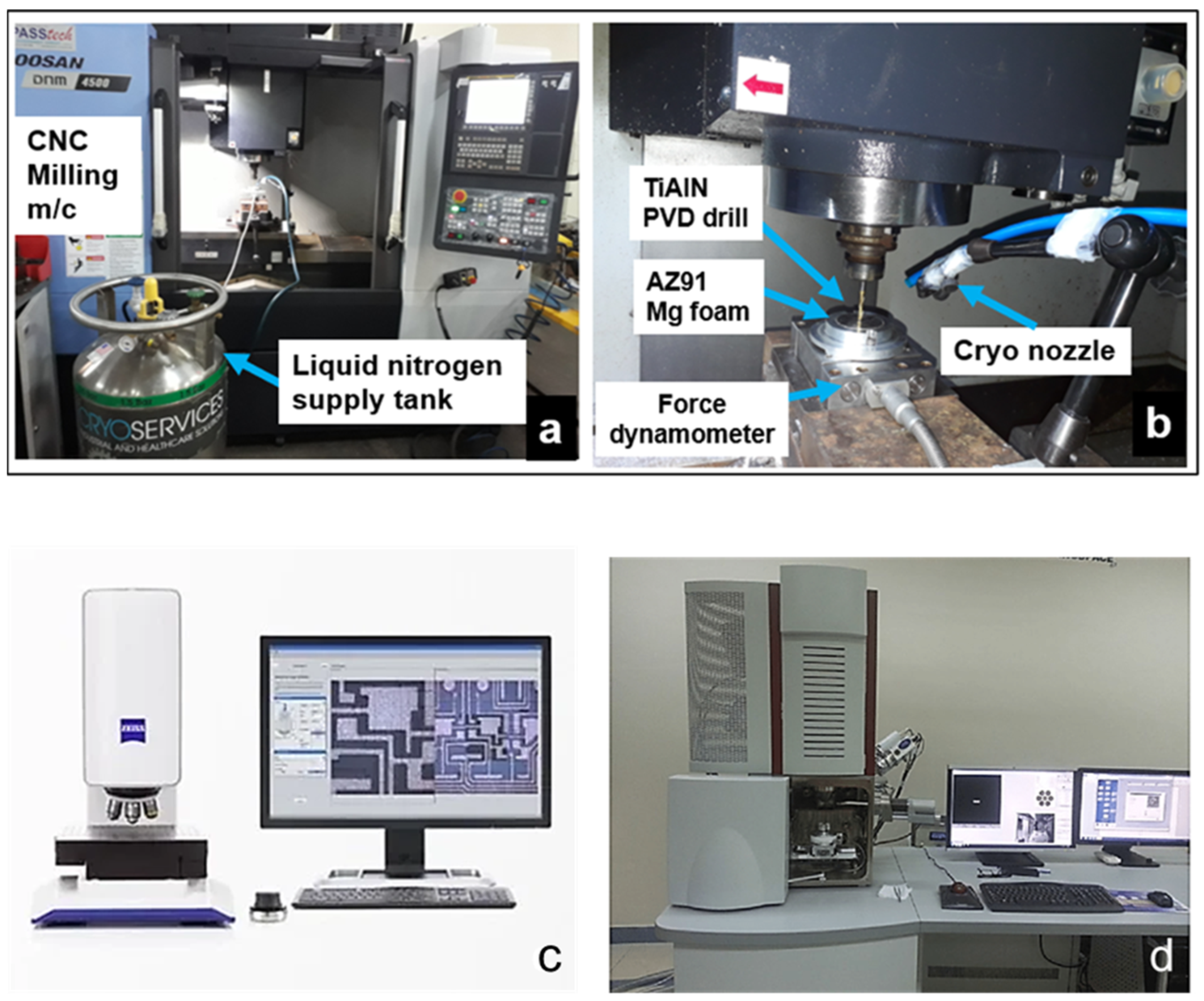
2. Material and Methods
2.1. Twist Drills
2.2. Drilling and Lubrication Conditions
2.3. Machining Force, Surface Roughness, Burr Formation, and Chip Morphology
2.4. AdvantEdgeTM Model
3. Results and Discussion
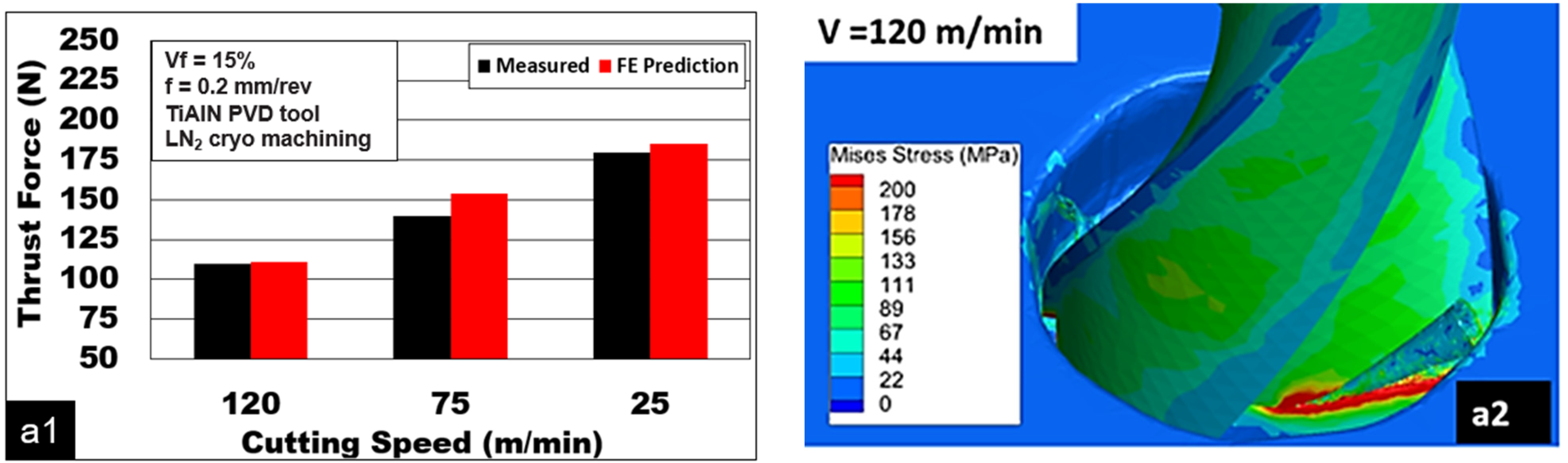
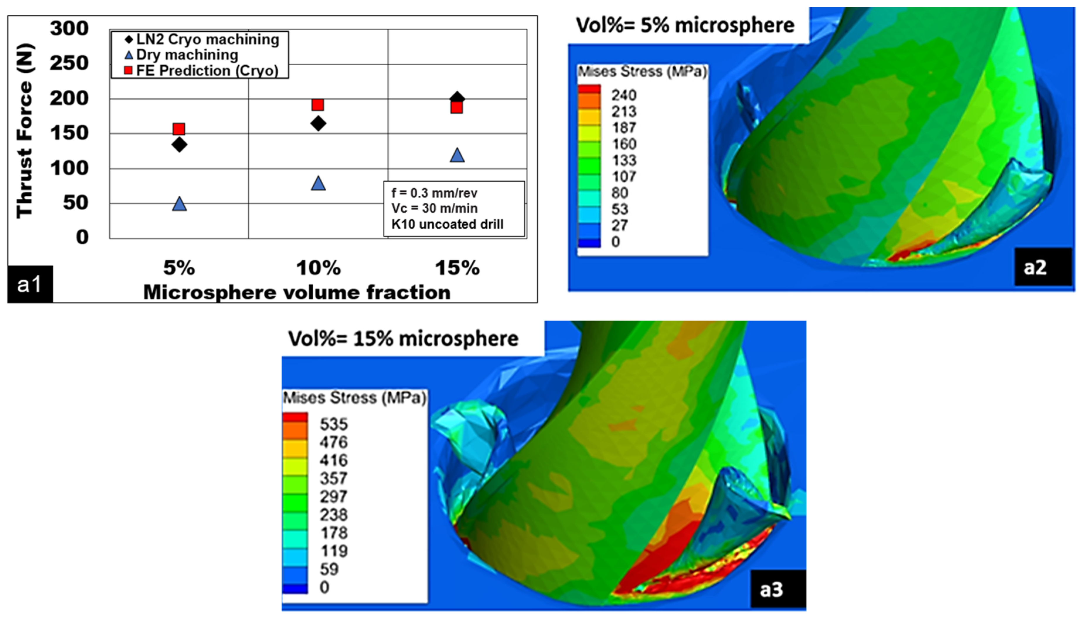
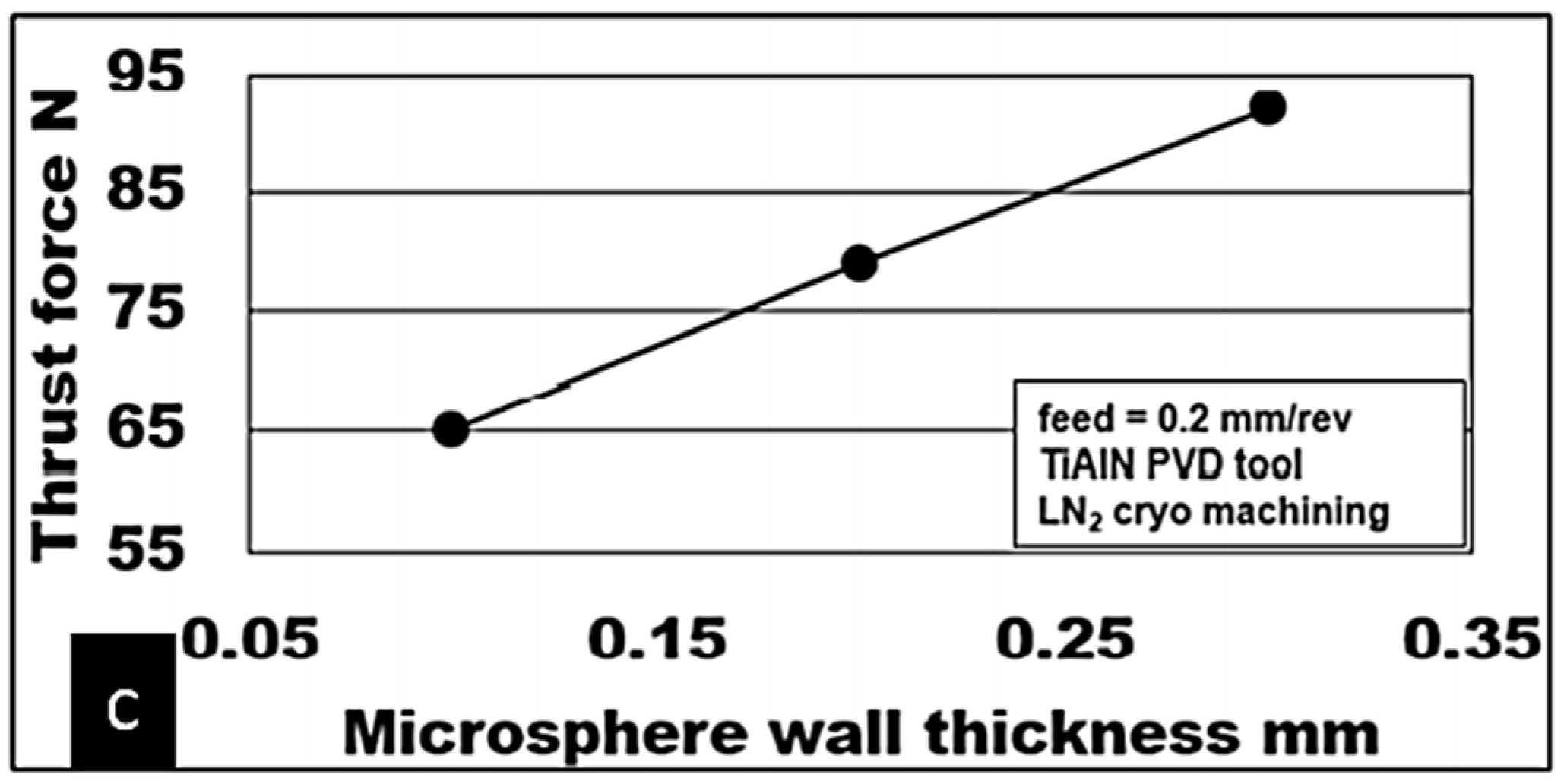
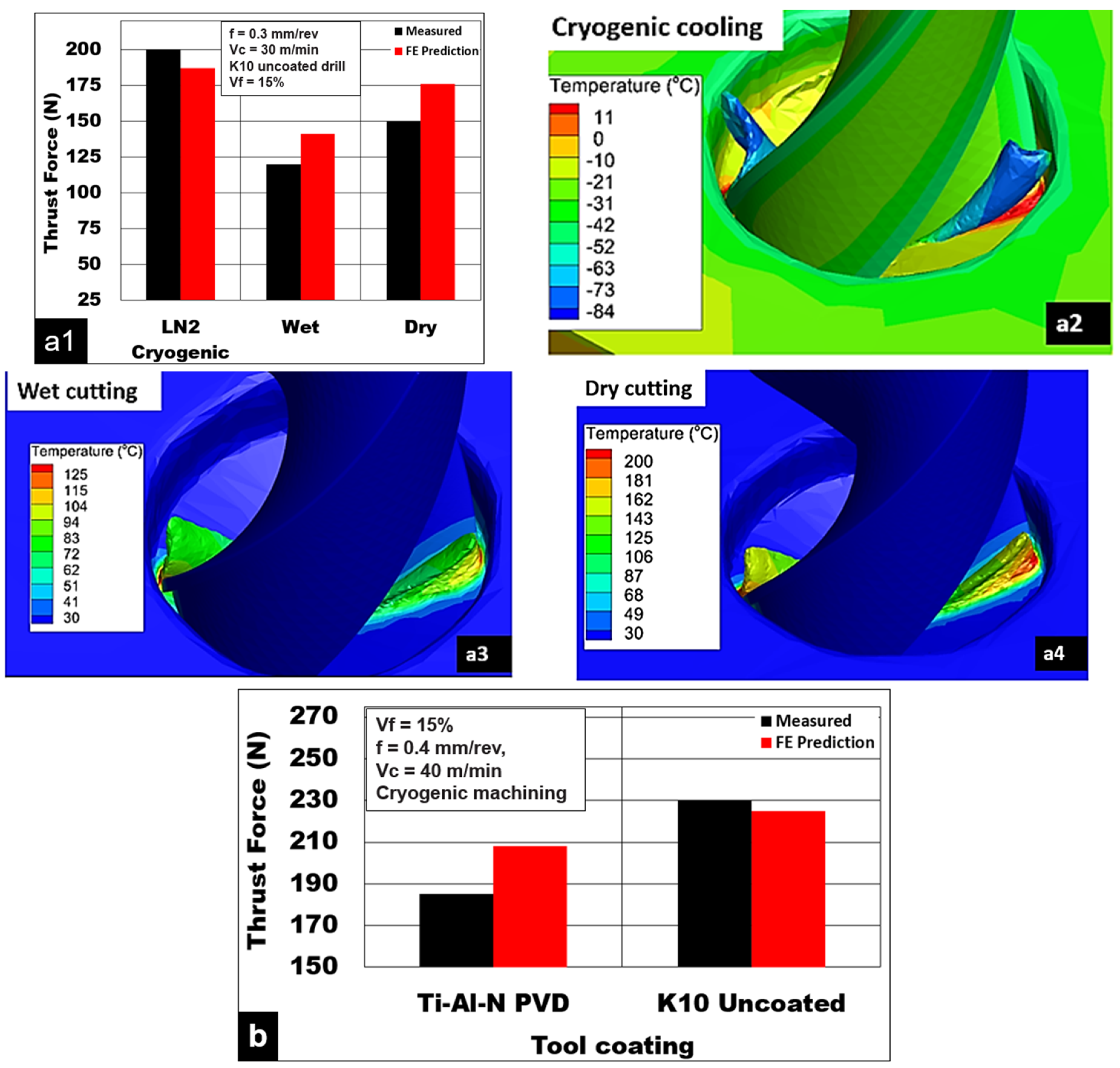
3.1. Thrust Force
3.2. Surface Quality and Integrity
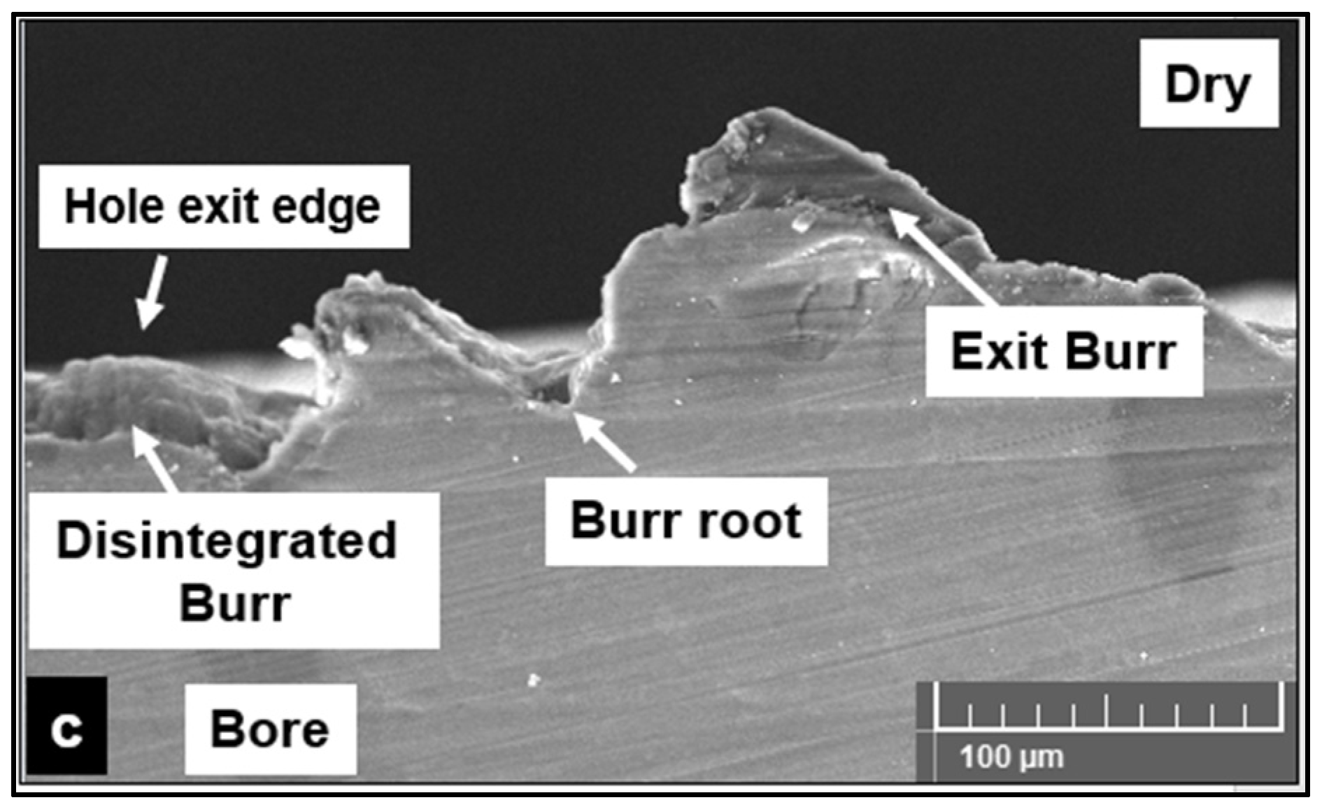
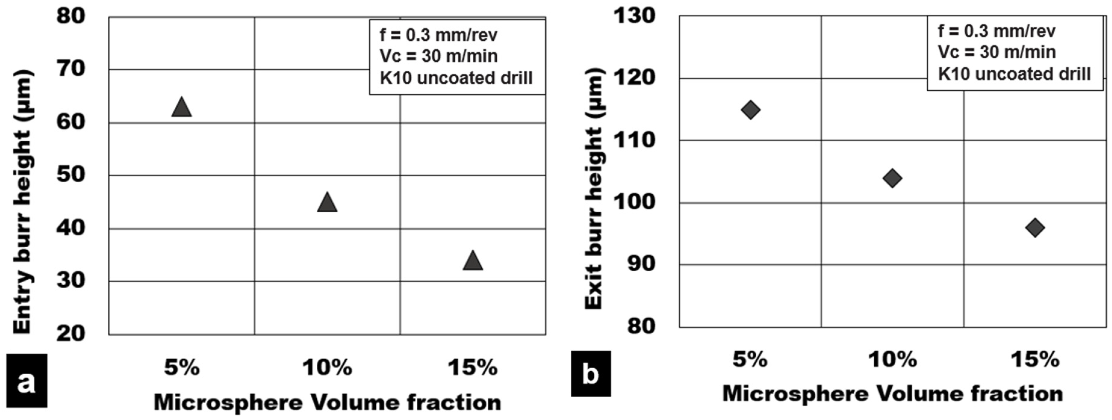
3.3. Drilling Burr Formation
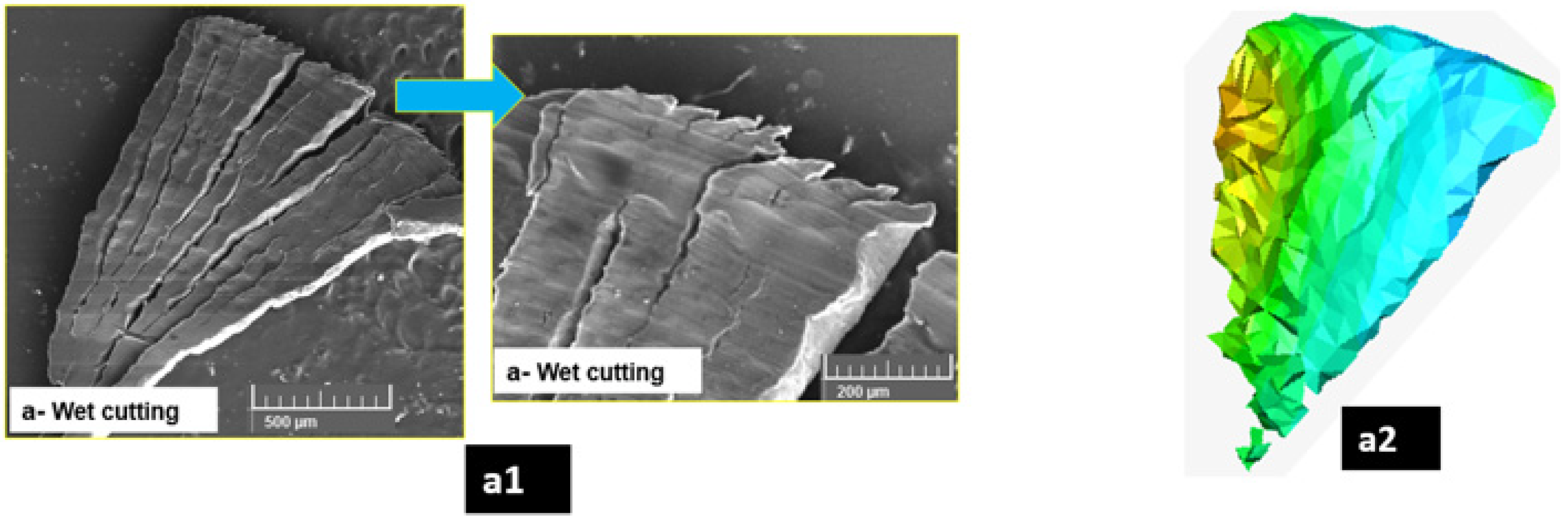
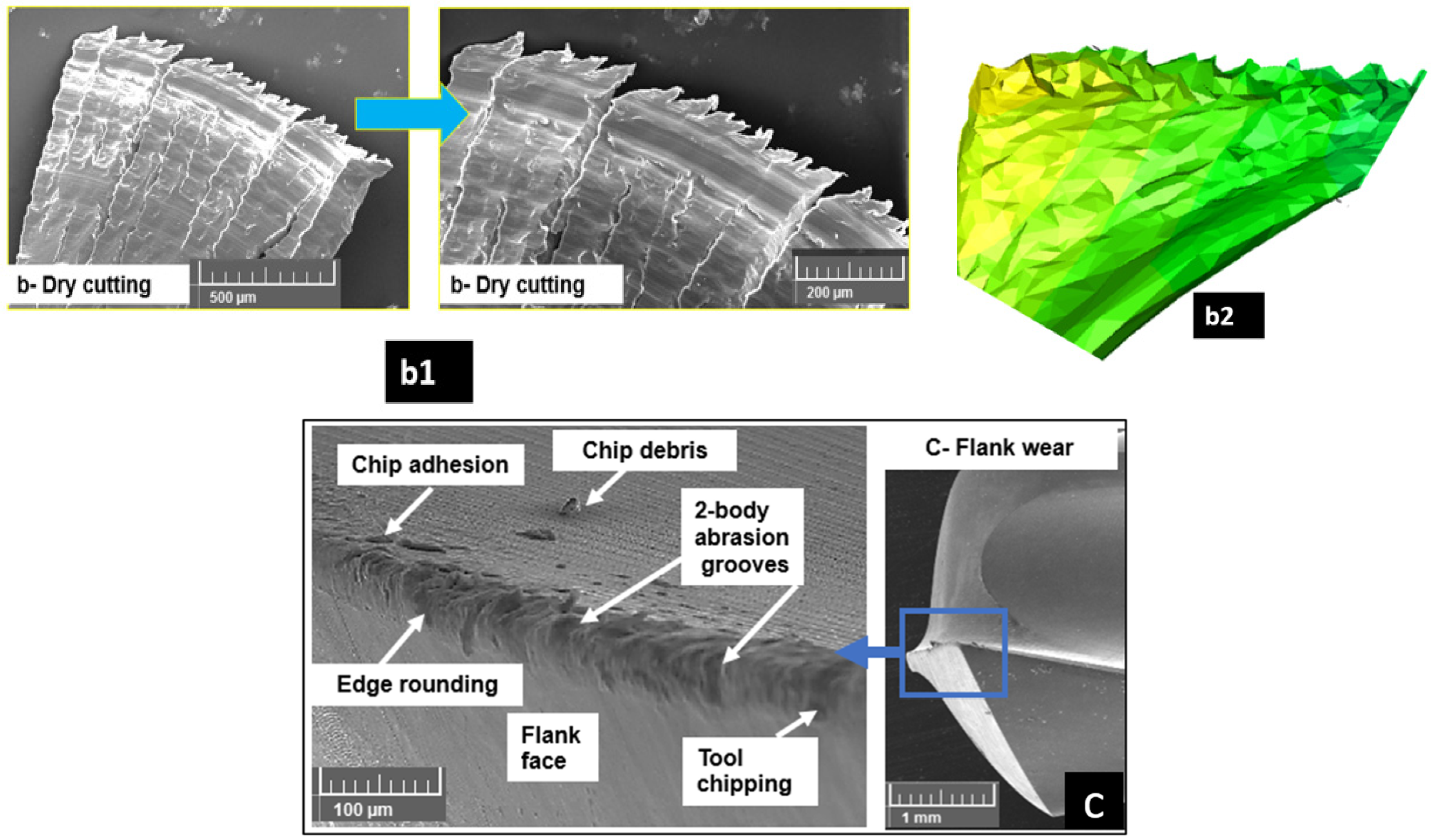
3.4. Chip Morphology
4. Conclusions
- Thrust force increased by almost 200% with an increase in the volume fraction of ceramic bubbles from 5% to 15% under cryogenic cooling conditions.
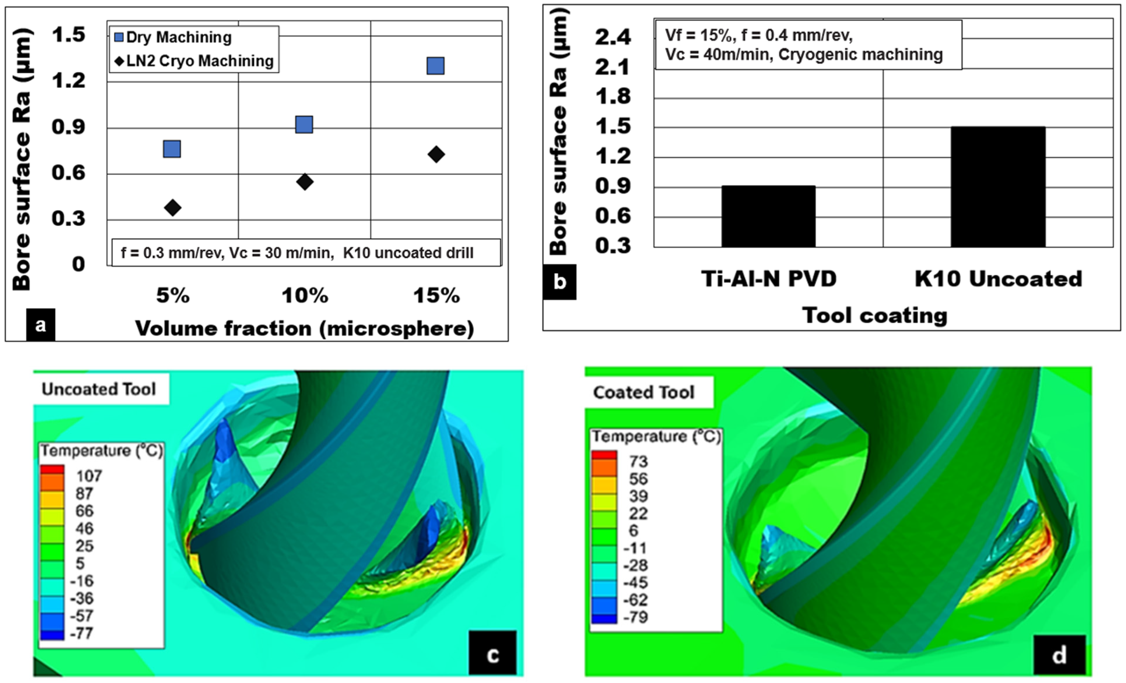
- A reduction in cutting forces and temperature is observed using Ti-Al-N PVD-coated drills compared to uncoated drills under cryogenic machining by approximately 20% and 30%, respectively.
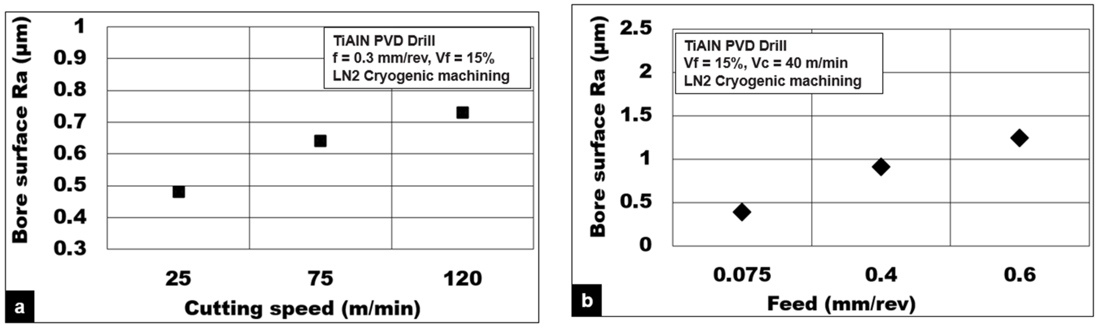
- A 40% decrease in thrust force is observed with an increase in cutting speed from 25 to 120 m/min under cryogenic cooling. This is attributed to the effects of material thermal softening behavior.
- An increase in the feed from 0.075 to 0.6 mm/rev results in higher thrust forces during cryogenic drilling (increase from 85 to 259 N). This is attributed primarily due to an increase in chip load and a higher percentage of ceramic bubble reinforcements in contact with the cutting tool.
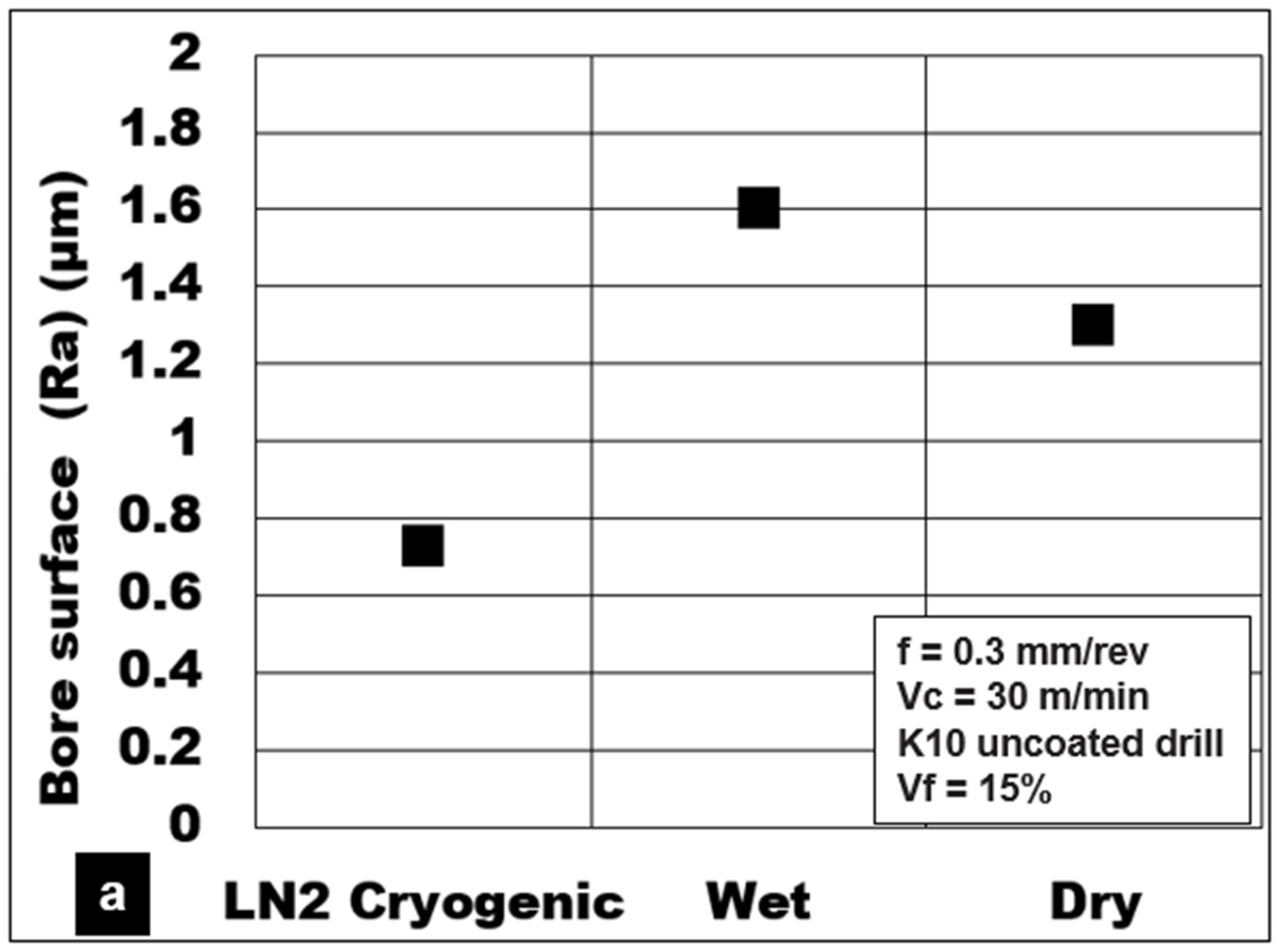
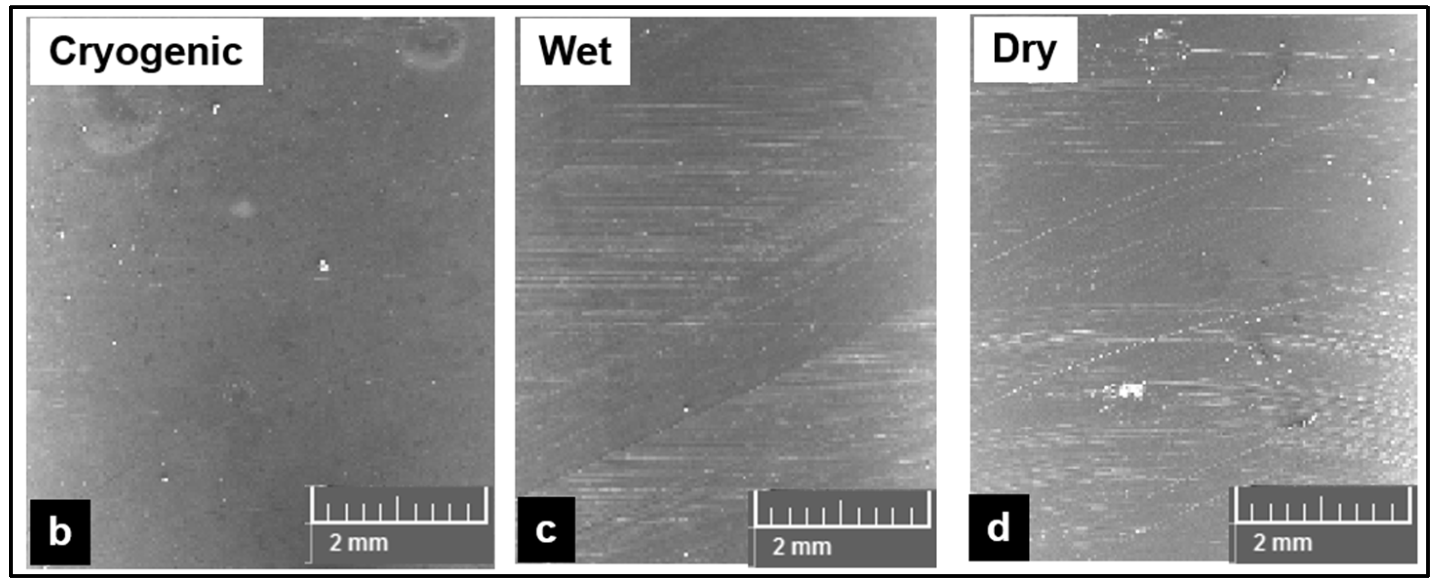
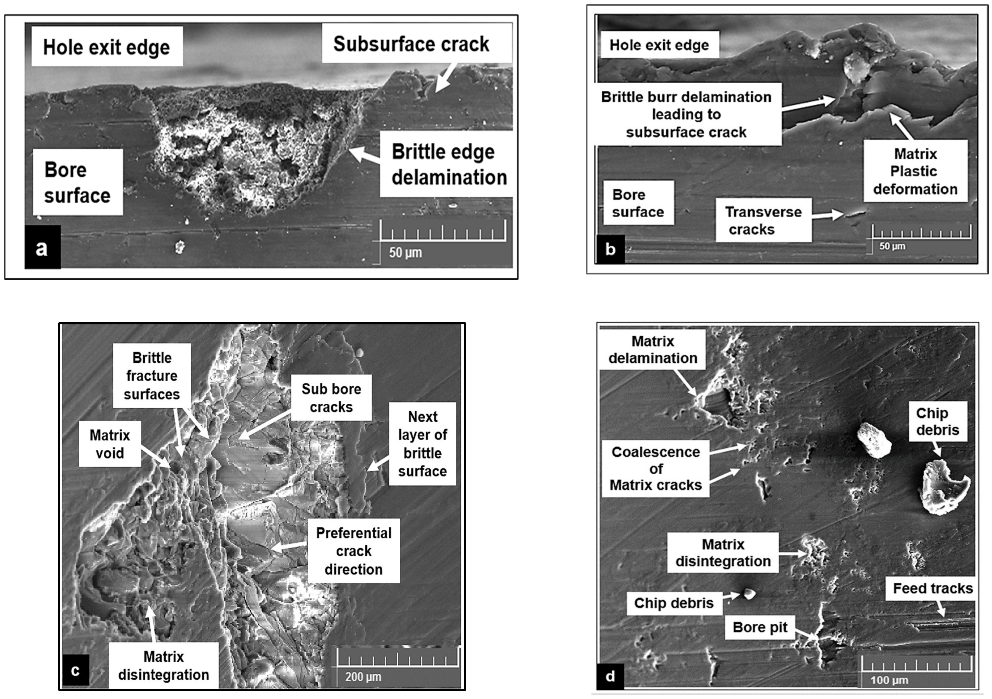
- Surface finish (Ra) showed a 45–55% improvement during cryogenic drilling of 15% syntactic foams with minimized subsurface damages compared to dry and wet cutting conditions. The higher the volume fraction, the higher the surface roughness (Ra).
Author Contributions
Funding
Institutional Review Board Statement
Informed Consent Statement
Data Availability Statement
Acknowledgments
Conflicts of Interest
References
- Parande, G.; Manakari, V.; Meenashisundaram, G.K.; Gupta, M. Enhancing the Tensile and Ignition Response of Monolithic Magnesium by Reinforcing with Silica Nanoparticulates. J. Mater. Res. 2017, 32, 2169–2178. [Google Scholar] [CrossRef]
- Kumar, K.; Gill, R.S.; Batra, U. Challenges and Opportunities for Biodegradable Magnesium Alloy Implants. Mater. Technol. 2018, 33, 153–172. [Google Scholar] [CrossRef]
- Pereira, H.; Carvalho, O.; Miranda, G.; Silva, F.S. Pure Magnesium Laser Surface Modification Using Nd:YAG Laser. Mater. Technol. 2021, 36, 811–815. [Google Scholar] [CrossRef]
- Azoubib, J.; Nawrocki, J.; Lewandowski, W. Independent Atomic Timescale in Poland—Organization and Results. Metrologia 2003, 40, S245–S248. [Google Scholar] [CrossRef]
- Manakari, V.; Kannan, S.; Parande, G.; Doddamani, M. In-Vitro Degradation of Hollow Silica Reinforced Magnesium Syntactic Foams in Di Ff Erent Simulated Body Fluids for Biomedical Applications. Metals 2020, 10, 1583. [Google Scholar] [CrossRef]
- Mozafari, M.; Bordbar-Khiabani, A.; Yarmand, B. Emerging Magnesium-Based Biomaterials for Orthopedic Implantation. Emerg. Mater. Res. 2020, 8, 305–319. [Google Scholar] [CrossRef]
- Kannan, S.; Pervaiz, S.; Alhourani, A.; Klassen, R.J.; Selvam, R.; Haghshenas, M. On the Role of Hollow Aluminium Oxide Microballoons during Machining of AZ31 Magnesium Syntactic Foam. Materials 2020, 13, 3534. [Google Scholar] [CrossRef]
- Kannan, S.; Pervaiz, S.; Klassen, R.J.; Huo, D.; Haghshenas, M. An Energy-Based Analysis for Machining Novel AZ91 Magnesium Composite Foam Dispersed with Ceramic Microspheres. J. Manuf. Sci. Eng. 2021, 143, 1–10. [Google Scholar] [CrossRef]
- Davis, B.; Dabrow, D.; Ju, L.; Li, A.; Xu, C.; Huang, Y. Study of Chip Morphology and Chip Formation Mechanism during Machining of Magnesium-Based Metal Matrix Composites. In Proceedings of the ASME 2017 12th International Manufacturing Science and Engineering Conference Collocated with the JSME/ASME 2017 6th International Conference on Materials and Processing, Los Angeles, CA, USA, 4 June 2017; pp. 1–9. [Google Scholar] [CrossRef]
- Mahajan, A.; Sidhu, S.S. Surface Modification of Metallic Biomaterials for Enhanced Functionality: A Review. Mater. Technol. 2018, 33, 93–105. [Google Scholar] [CrossRef]
- Wang, H.; Estrin, Y.; Fu, H.; Song, G.; Zúberová, Z. The Effect of Pre-Processing and Grain Structure on the Bio-Corrosion and Fatigue Resistance of Magnesium Alloy AZ31. Adv. Eng. Mater. 2007, 9, 967–972. [Google Scholar] [CrossRef]
- Kaynak, Y.; Lu, T.; Jawahir, I.S. Cryogenic Machining-Induced Surface Integrity: A Review and Comparison with Dry, Mql, and Flood-Cooled Machining. Mach. Sci. Technol. 2014, 18, 149–198. [Google Scholar] [CrossRef]
- Pu, Z.; Outeiro, J.C.; Batista, A.C.; Dillon, O.W.; Puleo, D.A.; Jawahir, I.S. Enhanced Surface Integrity of AZ31B Mg Alloy by Cryogenic Machining towards Improved Functional Performance of Machined Components. Int. J. Mach. Tools Manuf. 2012, 56, 17–27. [Google Scholar] [CrossRef]
- Pereira, O.; Rodríguez, A.; Calleja-Ochoa, A.; Celaya, A.; de Lacalle, L.N.L.; Fernández-Valdivielso, A.; González, H. Simulation of Cryo-Cooling to Improve Super Alloys Cutting Tools. Int. J. Precis. Eng. Manuf. Green Technol. 2022, 9, 73–82. [Google Scholar] [CrossRef]
- Pereira, O.; Celaya, A.; Urbikaín, G.; Rodríguez, A.; Fernández-Valdivielso, A.; Noberto López de Lacalle, L. CO2 Cryogenic Milling of Inconel 718: Cutting Forces and Tool Wear. J. Mater. Res. Technol. 2020, 9, 8459–8468. [Google Scholar] [CrossRef]
- Dinesh, S.; Senthilkumar, V.; Asokan, P. Experimental Studies on the Cryogenic Machining of Biodegradable ZK60 Mg Alloy Using Micro-Textured Tools. Mater. Manuf. Process. 2017, 32, 979–987. [Google Scholar] [CrossRef]
- Koklu, U.; Coban, H. Effect of Dipped Cryogenic Approach on Thrust Force, Temperature, Tool Wear and Chip Formation in Drilling of AZ31 Magnesium Alloy. J. Mater. Res. Technol. 2020, 9, 2870–2880. [Google Scholar] [CrossRef]
- Venkatesan, K.; Ramanujam, R.; Joel, J.; Jeyapandiarajan, P.; Vignesh, M.; Tolia, D.J.; Krishna, R.V. Study of Cutting Force and Surface Roughness in Machining of Al Alloy Hybrid Composite and Optimized Using Response Surface Methodology. Procedia Eng. 2014, 97, 677–686. [Google Scholar] [CrossRef]
- Outeiro, J.C.; Rossi, F.; Fromentin, G.; Poulachon, G.; Germain, G.; Batista, A.C. Process Mechanics and Surface Integrity Induced by Dry and Cryogenic Machining of AZ31B-O Magnesium Alloy. Procedia CIRP 2013, 8, 487–492. [Google Scholar] [CrossRef]
- Teng, X.; Huo, D.; Wong, E.; Meenashisundaram, G.; Gupta, M. Micro-Machinability of Nanoparticle-Reinforced Mg-Based MMCs: An Experimental Investigation. Int. J. Adv. Manuf. Technol. 2016, 87, 2165–2178. [Google Scholar] [CrossRef] [Green Version]
- Sun, F.; Huo, D.; Fu, G.; Teng, X.; Kannan, S.; Zhang, H. Micro-Drilling of Mg-Based MMCs Reinforced with SiO2 Nanoparticles: An Experimental Approach. Proc. Inst. Mech. Eng. Part B J. Eng. Manuf. 2020, 234, 1473–1485. [Google Scholar] [CrossRef]
- Kheireddine, A.H.; Ammouri, A.H.; Lu, T.; Jawahir, I.S.; Hamade, R.F. An FEM Analysis with Experimental Validation to Study the Hardness of In-Process Cryogenically Cooled Drilled Holes in Mg AZ31b. Procedia CIRP 2013, 8, 588–593. [Google Scholar] [CrossRef]
- Bhowmick, S.; Lukitsch, M.J.; Alpas, A.T. Dry and Minimum Quantity Lubrication Drilling of Cast Magnesium Alloy (AM60). Int. J. Mach. Tools Manuf. 2010, 50, 444–457. [Google Scholar] [CrossRef]
- Berzosa, F.; De Agustina, B.; Rubio, E.M. Tool Selection in Drilling of Magnesium UNSM11917 Pieces under Dry and MQL Conditions Based on Surface Roughness. Procedia Eng. 2017, 184, 117–127. [Google Scholar] [CrossRef]
- De Agustina, B.; Berzosa, F.; Rubio, E.M.; Marín, M.M. Experimental Study of Magnesium Drilling Based on the Surface Quality. Procedia CIRP 2019, 79, 74–78. [Google Scholar] [CrossRef]
- Arai, M.; Sato, S.; Ogawa, M.; Shikata, H. Materials Processing Technology Chip Control in Finish Cutting of Magnesium Alloy. J. Mater. Process. Technol. 1996, 62, 341–344. [Google Scholar] [CrossRef]
- Tomac, N.; Tonnessen, K.; Rasch, F.O. Formation of Flank Build-up in Cutting Magnesium Alloys. CIRP Ann. 1991, 40, 79–82. [Google Scholar] [CrossRef]
- Wang, J.; Liu, Y.B.; An, J.; Wang, L.M. Wear Mechanism Map of Uncoated HSS Tools during Drilling Die-Cast Magnesium Alloy. Wear 2008, 265, 685–691. [Google Scholar] [CrossRef]
- Bhowmick, S.; Alpas, A.T. The Role of Diamond-like Carbon Coated Drills on Minimum Quantity Lubrication Drilling of Magnesium Alloys. Surf. Coatings Technol. 2011, 205, 5302–5311. [Google Scholar] [CrossRef]
- Chen, S.; Head, D.; Effgen, M.; Jawahir, I.S. An Investigation of Sustained Machining Performance for Controlled Surface Quality Requirements in Porous Tungsten. IEEE Trans. Electron Devices 2005, 52, 903–908. [Google Scholar] [CrossRef]
- Schoop, J.; Effgen, M.; Balk, T.J.; Jawahir, I.S. Improved Product Quality and Resource Efficiency in Porous Tungsten Machining for Dispenser Cathode Application by Elimination of the Infiltration Process. In Re-Engineering Manufacturing for Sustainability; Springer: Singapore, 2013; pp. 241–244. [Google Scholar] [CrossRef]
- Heidari, M.; Yan, J. Ultraprecision Surface Flattening of Porous Silicon by Diamond Turning. Precis. Eng. 2017, 49, 262–277. [Google Scholar] [CrossRef]
- Pusavec, F. Porous Tungsten Machining under Cryogenic Conditions. Int. J. Refract. Met. Hard Mater. 2012, 35, 84–89. [Google Scholar] [CrossRef]
- Kumar Reddy Sirigiri, V.; Yadav Gudiga, V.; Shankar Gattu, U.; Suneesh, G.; Mohan Buddaraju, K. A Review on Johnson Cook Material Model. Mater. Today Proc. 2022, 62, 3450–3456. [Google Scholar] [CrossRef]
- Trojanova, Z.; Lukac, P. Hardening and Softening in Magnesium Alloys. In Magnesium Alloys-Design, Processing and Properties; IntechOpen: London, UK, 2011; pp. 1–20. [Google Scholar] [CrossRef]
- Sunil, B.R.; Ganesh, K.V.; Pavan, P.; Vadapalli, G.; Swarnalatha, C.; Swapna, P.; Bindukumar, P.; Pradeep Kumar Reddy, G. Effect of Aluminum Content on Machining Characteristics of AZ31 and AZ91 Magnesium Alloys during Drilling. J. Magnes. Alloys 2016, 4, 15–21. [Google Scholar] [CrossRef]
- Deng, J.; Wu, F.; Lian, Y.; Xing, Y.; Li, S. Erosion Wear of CrN, TiN, CrAlN, and TiAlN PVD Nitride Coatings. Int. J. Refract. Met. Hard Mater. 2012, 35, 10–16. [Google Scholar] [CrossRef]
- Hong, S.Y.; Ding, Y.; Jeong, W.C. Friction and Cutting Forces in Cryogenic Machining of Ti-6Al-4V. Int. J. Mach. Tools Manuf. 2001, 41, 2271–2285. [Google Scholar] [CrossRef]
- Joshi, S.S.; Ramakrishnan, N.; Ramakrishnan, P. Micro-Structural Analysis of Chip Formation During Orthogonal Machining of Al/SiCp Composites. J. Eng. Mater. Technol. 2000, 123, 315–321. [Google Scholar] [CrossRef]
- Zhang, H.; Kong, X.; Yang, L.; Wang, Y.; Chi, G. High Temperature Deformation Mechanisms and Constitutive Modeling for Al/SiCp/45 Metal Matrix Composites Undergoing Laser-Assisted Machining. Mater. Sci. Eng. A 2015, 642, 330–339. [Google Scholar] [CrossRef]


| Average Al2O3 Size (mm) | Alumina | Iron Oxide | Calcium Oxide | Silica | Sodium Oxide | Density (g/cm3) |
|---|---|---|---|---|---|---|
| 0.1–0.5 mm, 0.6–1 mm | 99.7 | 0.006 | 0.013 | 0.026 | 0.27 | 1.700 |
| Mg Alloy | 87 Mg | 9Al | 1.4Zn | Cu ≤ 0.1% | Mn ≤ 0.13% | Si ≤ 0.5% |
| Geometry | Coated Drill | K10 Drill |
|---|---|---|
| Grade | Titanium–Aluminum Nitride fine grade | K10 CARBIDE |
| Tool diameter (mm) | 5 | 5 |
| Number of flutes in tool | 3 | 3 |
| Shank diameter (mm) | 6 | 6 |
| Flute length (mm) | 20 | 35 |
| Point angle | 140° | 130° |
| Helix angle | 30° | 30° |
| Experiment Conditions | ||
|---|---|---|
| Matrix | Mg-9Al-1.4Zn | |
| Reinforcement | Hollow Al2O3 | |
| Microsphere (Volume fraction %) | 5%, 10%, 15% | |
| Drilling speed (m/min) | 40–120 | |
| Feed (mm/rev) | 0.075, 0.2, 0.4, 0.6 | |
| Sample thickness (mm) | 5 | |
| Cutting insert | Kennametal™ |
|
| Lubrication | LN2 Cryogenic, Almag® oil (Wet) Dry cutting | |
Publisher’s Note: MDPI stays neutral with regard to jurisdictional claims in published maps and institutional affiliations. |
© 2022 by the authors. Licensee MDPI, Basel, Switzerland. This article is an open access article distributed under the terms and conditions of the Creative Commons Attribution (CC BY) license (https://creativecommons.org/licenses/by/4.0/).
Share and Cite
Mohammed, A.; Kannan, S.; Pervaiz, S.; Ali, S.; Thomas, K.K.; Karthikeyan, R. Sustainable Machining of Mg-9Al-1.4Zn Foam Used for Temporary Biomedical Implant Using Cryogenic Cooling. Materials 2022, 15, 6678. https://doi.org/10.3390/ma15196678
Mohammed A, Kannan S, Pervaiz S, Ali S, Thomas KK, Karthikeyan R. Sustainable Machining of Mg-9Al-1.4Zn Foam Used for Temporary Biomedical Implant Using Cryogenic Cooling. Materials. 2022; 15(19):6678. https://doi.org/10.3390/ma15196678
Chicago/Turabian StyleMohammed, Abdalla, Sathish Kannan, Salman Pervaiz, Shafahat Ali, Kevin K. Thomas, and Ramanujam Karthikeyan. 2022. "Sustainable Machining of Mg-9Al-1.4Zn Foam Used for Temporary Biomedical Implant Using Cryogenic Cooling" Materials 15, no. 19: 6678. https://doi.org/10.3390/ma15196678