Article

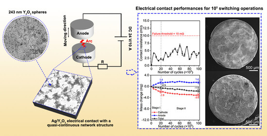
Quasi-Continuous Network Structure Greatly Improved the Anti-Arc-Erosion Capability of Ag/Y2O3 Electrical Contacts

1
Key Laboratory for Anisotropy and Texture of Materials (Ministry of Education), School of Materials Science and Engineering, Northeastern University, Shenyang 110819, China
2
State Key Laboratory of Advanced Technologies for Comprehensive Utilization of Platinum Metals, Kunming Institute of Precious Metals, Kunming 650106, China
3
Department of Chemical and Biological Engineering, William Mong Institute of Nano Science and Technology, The Hong Kong University of Science and Technology, Hong Kong 999077, China
4
Foshan Graduate School, Northeastern University, Foshan 528311, China
*
Authors to whom correspondence should be addressed.
Materials 2022, 15(7), 2450; https://doi.org/10.3390/ma15072450
Submission received: 12 February 2022 / Revised: 23 March 2022 / Accepted: 25 March 2022 / Published: 26 March 2022

Abstract

:
Ag/Y2O3 has excellent potential to replace Ag/CdO as the environmentally friendly electrical contact material. Using spherical Y2O3 as the starting material, Ag/Y2O3 contacts with a quasi-continuous network structure were successfully fabricated by a low-energy ball milling treatment. The mean size of Y2O3 used ranged from 243 to 980 nm. Due to the differences in the size of Y2O3, Ag/Y2O3 contacts had different primitive microstructures, thereby exhibiting distinctive anti-arc-erosion capabilities. Ag/Y2O3 contact prepared using 243 nm Y2O3 showed the best anti-arc-erosion capability and the most outstanding electrical performance measures, such as low contact resistance, less mass transfer, and no failure up to 105 cycle times. The quasi-continuous network structure formed in the micro-scale was responsible for the excellent electrical performance. The short distance between Y2O3 particles in the network promoted the cathode arc motion, and thus alleviated the localized erosion. The results obtained herein may inspire further attempts to design electrical contacts rationally.

Graphical Abstract

1. Introduction

Silver/cadmium oxide (Ag/CdO) has been the most favored electrical contact material in low-voltage electrical apparatuses since the 1960s [1,2]. Decomposition and evaporation of CdO could significantly resist the welding and erosion of the Ag matrix under multiple arcs [3]. However, cadmium is hazardous and banned in many countries [4]. The development of cadmium-free electrical contact materials has always been a worldwide issue. New materials, such as Ag/SnO2 [5,6], Ag/CuO [7,8], Ag/ZnO [9], Ag/MAX [10,11], Ag/TiB2 [12], and so on, have replaced Ag/CdO to some extent, but still face many problems, such as high and unstable contact resistance and serious ablation loss [13]. Therefore, designing and preparing new, environmentally friendly, high-performance electrical contacts has always been challenging.
Non-toxic yttrium oxide (Y2O3) has several advantages, which can be incorporated into the Ag matrix to form Ag/Y2O3 electrical contacts. Rare earth elements can promote recrystallization, refine the grains, and strengthen the matrix [14,15]. Y element’s high chemical activity [16] could help silver resist corrosion and maintain high electrical conductivity. Besides, Y2O3 has a high melting point (~2410 °C) and excellent thermal stability, thereby having outstanding high-temperature tolerance [17,18]. Fu et al. found that the addition of Y2O3 significantly enhances the wettability and machinability of Ag/SnO2 contacts [19]. Zhen et al. reported that yttrium-reinforced copper composites exhibit high hardness and low contact resistance [20]. In addition, our previous work showed that Ag/Y2O3 composites have high breakdown strength and less silver splashing under high-voltage spark [21]. The research on Ag/Y2O3 electrical contacts still draws enormous attention.
In addition to the composition, the microstructure also strongly influences the performance of electrical contacts. Zhang et al. found that reticulate graphene distributed in the Cu matrix endows the composite with high interfacial shear stress, thermal conductivity, and electrical conductivity [22,23]. Lin et al. showed that Ni networks could restrain the metal-pool flow and slow down the silver splashing [24,25]. Wang et al. indicated that a CuO skeleton in Ag/CuO contacts helps decrease the mass loss and prevent oxide aggregation in the eroded zone [26]. In all, the network structure could improve the composites’ mechanical strength, thermal conductivity, electrical conductivity, and anti-arc-erosion capability.
To date, published studies have provided outcomes on process parameters, microstructures, and mechanical properties of Y2O3-reinforced Al-based [27,28], Cu-based [29], and Ag-based [30] composites prepared by powder metallurgy. However, few works have been found on the electrical contact performance of Ag/Y2O3 contacts. This work aimed to prepare Ag/Y2O3 electrical contacts using spherical Y2O3 as the starting material and investigate the relationships between Y2O3 particle size, microstructure, and electrical contact performance. The phase, microstructure, and physical properties were characterized. Ag/Y2O3 contacts’ electrical contact performance was studied based on contact resistance, mass change, and the final eroded morphology. In addition, one-time eroded morphology was provided for exploring the size-effect mechanism. Research results are essential for designing and fabricating new Cd-free electrical contact materials and getting in-depth insights into the arc erosion mechanism.

2. Materials and Methods

2.1. Raw Materials

Ag powder (99.99% purity, mean size: 1 μm) was obtained from Kunming Sino-Platinum Metals Co., Ltd. (Kunming, China). Y(NO3)3∙6H2O (99.99%), urea (99%), ethanol (99.8%), and octadecanoic acid (99.99%) were purchased from Shanghai Sinopharm Group Co., Ltd. (Shanghai, China). All reagents were used without further purification.

2.2. Synthesis of Spherical Y2O3 Powders with Different Sizes

Two spherical Y2O3 precursors were prepared by forcing urea hydrolysis in Y(NO3)3 solution (0.015 mol/L) at 90 °C for 2 h. The molar ratios of Y(NO3)3∙6H2O to urea were 1:133 and 1:33, respectively. The precursor particles were centrifugally separated and washed with deionized water and ethanol. After annealing at 800 °C for 2 h, the precursors shift to spherical Y2O3 powders of particle size in between 200 and 400 nm.
To synthesize two larger-size Y2O3 spheres, the as-prepared spherical precursors were used as the seeds. First, 1 g seeds was dispersed in a 1 L aqueous solution, which contained Y(NO3)3 (0.015 mol/L) and urea (0.5 mol/L). Then, the mixture was heated to 90 °C and held for 2 h to obtain new precursors. After the same treatment as the seeds, the new precursors turned into Y2O3 spheres of particle sizes in between 700 and 1000 nm.

2.3. Fabrication of Ag/Y2O3 Sintered Compacts

Figure 1 shows the route to prepare Ag/Y2O3 sintered compact. Ag and spherical Y2O3 powders were mixed in ethanol under ultrasonic agitation. The mass ratio of Y2O3 to Ag was 9.9%. After drying the ethanol, the obtained powder was mixed in a mortar using 5 wt.‰ octadecanoic acids as a process control agent. Then, to improve the mixing and avoid the breakage of Y2O3 spheres, the mixed powder was milled in a horizontal jar mill for 4 h at 100 rpm. Stainless steel balls were used in ball-milling, and the ball-to-powder ratio was 10:1. The well-mixed Ag/Y2O3 powder was calcined at 400 °C for 2 h, then densified by hot-pressing at 750 °C and 55 MPa for 1 h in an argon atmosphere. Ag/Y2O3 sintered compacts were thereby obtained.

2.4. Characterization

X-ray diffraction (XRD, Smartlab 9, Cu Kα, λ = 1.5406 Å) was utilized to determine the phase, with a scanning rate of 4° 2θ/min. Microstructures were characterized by scanning electron microscopy (SEM, JSM-7001F). Image J software was used to analyze the particles’ size. Samples of ϕ14 mm × 5 mm were machined from the sintered compacts for physical property tests. The density was measured using Archimedes’ method. Vickers hardness tester (401MVD) was adopted to evaluate the hardness at a load of 100 g for 10 s. The electrical conductivity was detected by a vortex conductivity apparatus (FQR7501). Values of hardness and electrical conductivity are statistics based on at least 10 readings for each sample.
The sintered compacts were machined into electrodes (ϕ3 mm × 1.5 mm) for electrical contact tests. The test apparatus (Figure S1a) was set up to simulate the switching operation at DC 24 V/10 A. The contact gap between the two electrodes was 10 mm, and the electrodes were contacted for 105 times at the frequency of 1 Hz. After each 5000-switching operation, the contact resistance between two electrodes was detected by the Kelvin four-terminal sensing method (Figure S1b). The failure occurred once the value of contact resistance was larger than 10 mΩ [31]. The mass changes were recorded as well.

3. Results and Discussion

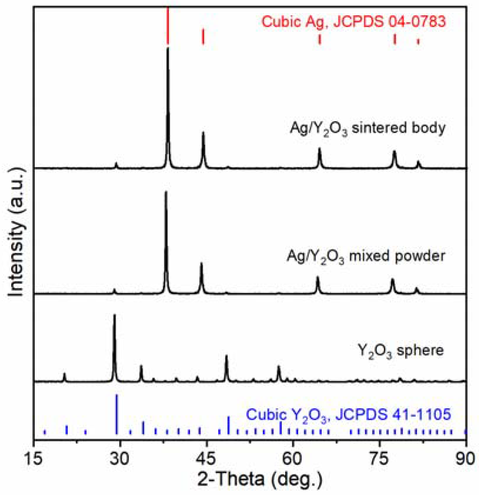
3.1. Phase, Microstructure, and Physical Properties

Y2O3 spheres have a cubic structure, which can be indexed to JCPDS No. 41-1105 [32], as shown in Figure 2. Ag/Y2O3 mixed powder and sintered body show diffraction patterns of both Ag and Y2O3. The diffraction pattern of Ag is indexed to JCPDS No. 04-0783 [33]. No other crystalline phases were observed.
Figure 3 shows the SEM morphologies and size distribution of spherical Y2O3 powders. Spherical Y2O3 powders with narrow size distribution were obtained. The mean sizes of the four powders were 243, 387, 792, and 980 nm, respectively. Particles were individually separated. No aggregation, coalescence, or sintering occurred. After thoroughly mixing with silver powder, Y2O3 particles retained the spherical shape and good dispersibility, as shown in Figure S2. It can be seen that Ag and Y2O3 particles are well mixed, which means the sintered body would have a uniform microstructure.
Figure 4 shows the microstructure of Ag/Y2O3 sintered compacts. The light area represents the silver phase, while the dark zone is the Y2O3 phase. After hot-press sintering, Y2O3 retained the spherical shape and formed a quasi-continuous network structure in the Ag matrix. The network structure is different due to the differences in the size of Y2O3. The main difference is the distance between the adjacent Y2O3 particles, which decreases with the size of Y2O3. Among the four samples, the sintered compact using 243 nm Y2O3 particles as the raw material has the shortest distance between the adjacent Y2O3 particles. The unique quasi-continuous network structure would significantly improve electrical performances.
Ag and Y2O3 powders were firstly mixed in ethanol solution under ultrasonic agitation in our work. Ultrasonic stirring could disperse and activate Ag and Y2O3 particles. Meanwhile, Y2O3 spheres could be adsorbed on the silver surface by Van der Waals force and Coulomb force [34]. After drying the ethanol solution, the obtained powder was further mixed by hand grinding and ball milling to avoid the delamination caused by density differences. Then, annealing was conducted to remove the organics and other volatile purities. Finally, the well-mixed Ag/Y2O3 powder was densified by hot-pressing, and the quasi-continuous network structure was thus formed in the sintered body in a micro-scale. It is difficult to achieve the microstructure refinement and homogenization by a low-energy ball milling for the soft metal matrix composite due to the superplasticity of metal particles [27,28,35,36]. However, both Ag and Y2O3 phases remained their original size and shape in our sintered compacts to a large extent. Thus, our method enables the design and regulation of the material microstructure in the soft metal matrix composite, facilitating further study on the structure–property relationship.
The mechanical and electrical properties of Ag/Y2O3 sintered compacts are listed in Table 1. Although no voids were observed in the SEM analysis, all samples’ relative densities are below 100%. This result can be due to the incomplete sintering of Y2O3 particles. It is well known that the densification temperature of Y2O3 is above 1900 °C [17,37]. However, the hot-pressing temperature in this work is only 750 °C, which is too low to densify Y2O3 particles. All sintered bodies exhibit high hardness and high conductivity. The highest conductivity is up to 73.0 IACS%.

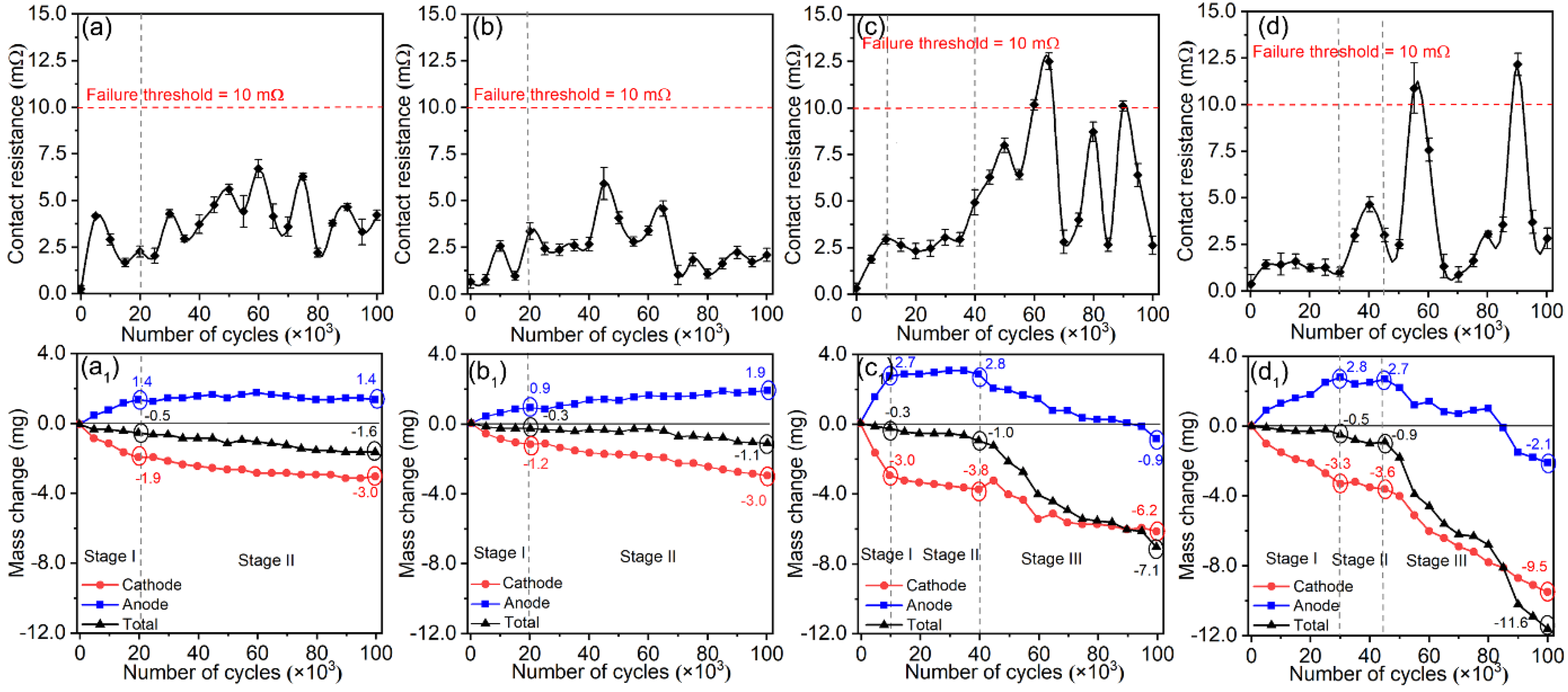
3.2. Electrical Contact Performances of Ag/Y2O3 Contacts

Figure 5 shows the variation in contact resistance (Rc) and mass of Ag/Y2O3 contacts during the electrical contact test. The contact resistances were low and stable during the whole test for the contacts prepared using 243 nm and 387 nm Y2O3. However, intermittent failure (Rc > 10 mΩ) occurred after 5 × 10⁴ switching operations for the other two contacts. The mass changes were also different between the four contacts and divided into several stages, as shown in Figure 5(a1–d1). In stage I and stage II, the material transfer direction was from the cathode to the anode. Thus, the mass of the anode increased as the cycle number increased, while the mass of the cathode decreased. Stage III was found for the contacts prepared using 792 nm and 980 nm Y2O3. In stage III, the mass of both anode and cathode decreased as the cycle number increased, and the failure occurred after a sudden mass drop of the anode. According to the theory of electrical contacts [38,39], the electric current between the anode and cathode is achieved through the interface’s metal-to-metal spots (α-spots). The mass abruptly decreased once the spalling occurred, which produced a sudden decrease in α-spots. Simultaneously, the electrode surfaces were severely worsened, increasing the contact resistance sharply. The analysis of the worsened microstructure will be shown later. In all, the contacts prepared using 243 nm and 387 nm spherical Y2O3 exhibited outstanding electrical contact performance measures, such as low contact resistance, stable mass transfer from the cathode to anode, and no failure up to 105 cycles tests.
The morphologies of cathode and anode after 105 cycle tests are shown in Figure 6. The contact prepared using 243 nm spherical Y2O3 shows relatively uniform erosion across the whole surface. Corrosion pits are observed on both the cathode and anode. As for the surface of contact prepared using 387 nm Y2O3, most parts show relatively uniform erosion, but a crater and protrusion appear, as shown in Figure 6b,b1. The other two contacts show more severe erosion on both the cathode and anode. These results agree well with the change in the contact resistance and mass shown in Figure 5. Research [40,41] has pointed out that a relatively uniform and smooth surface means more contact spots, thereby creating more electron transfer paths and reducing the contact resistance.

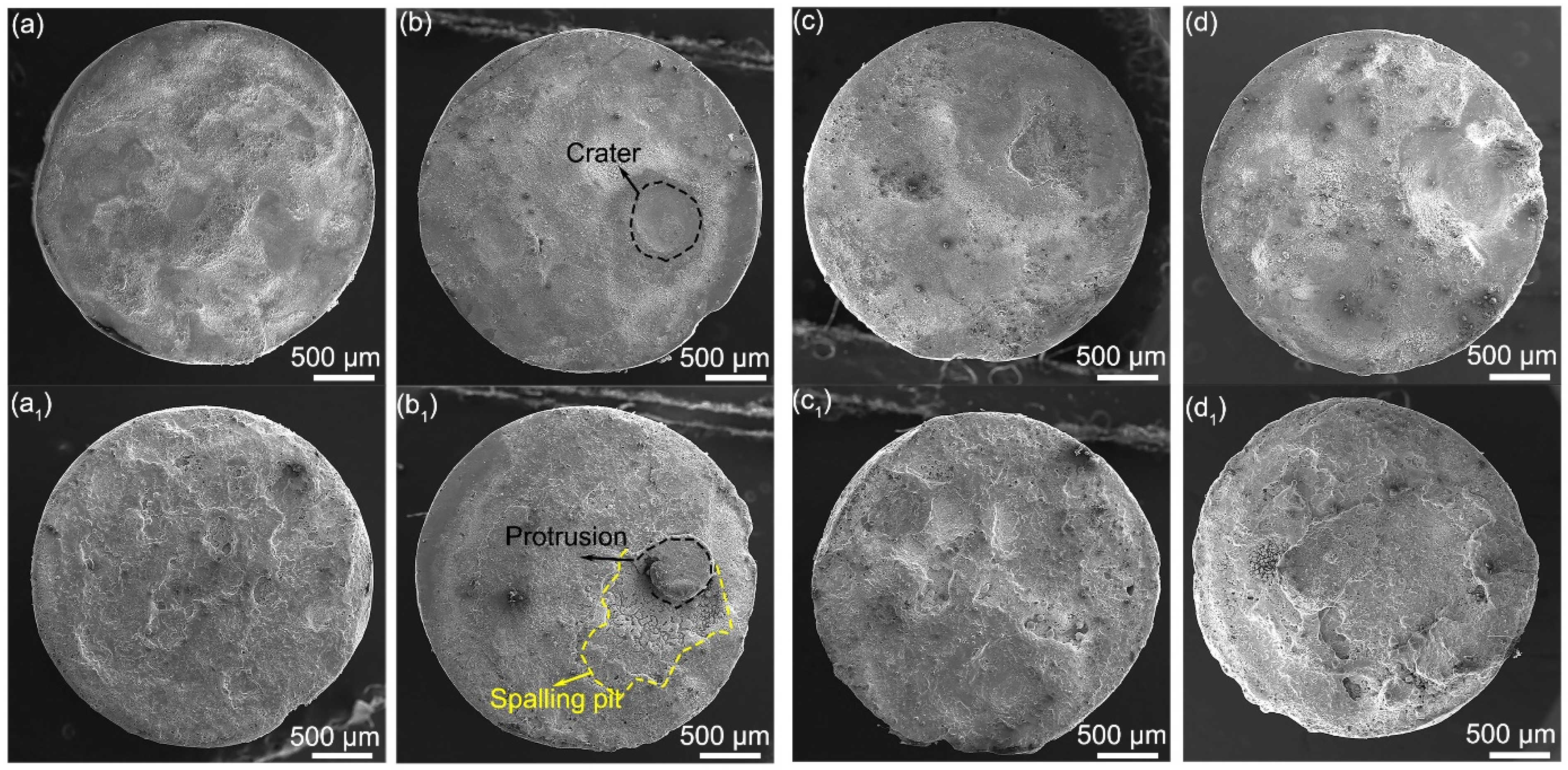
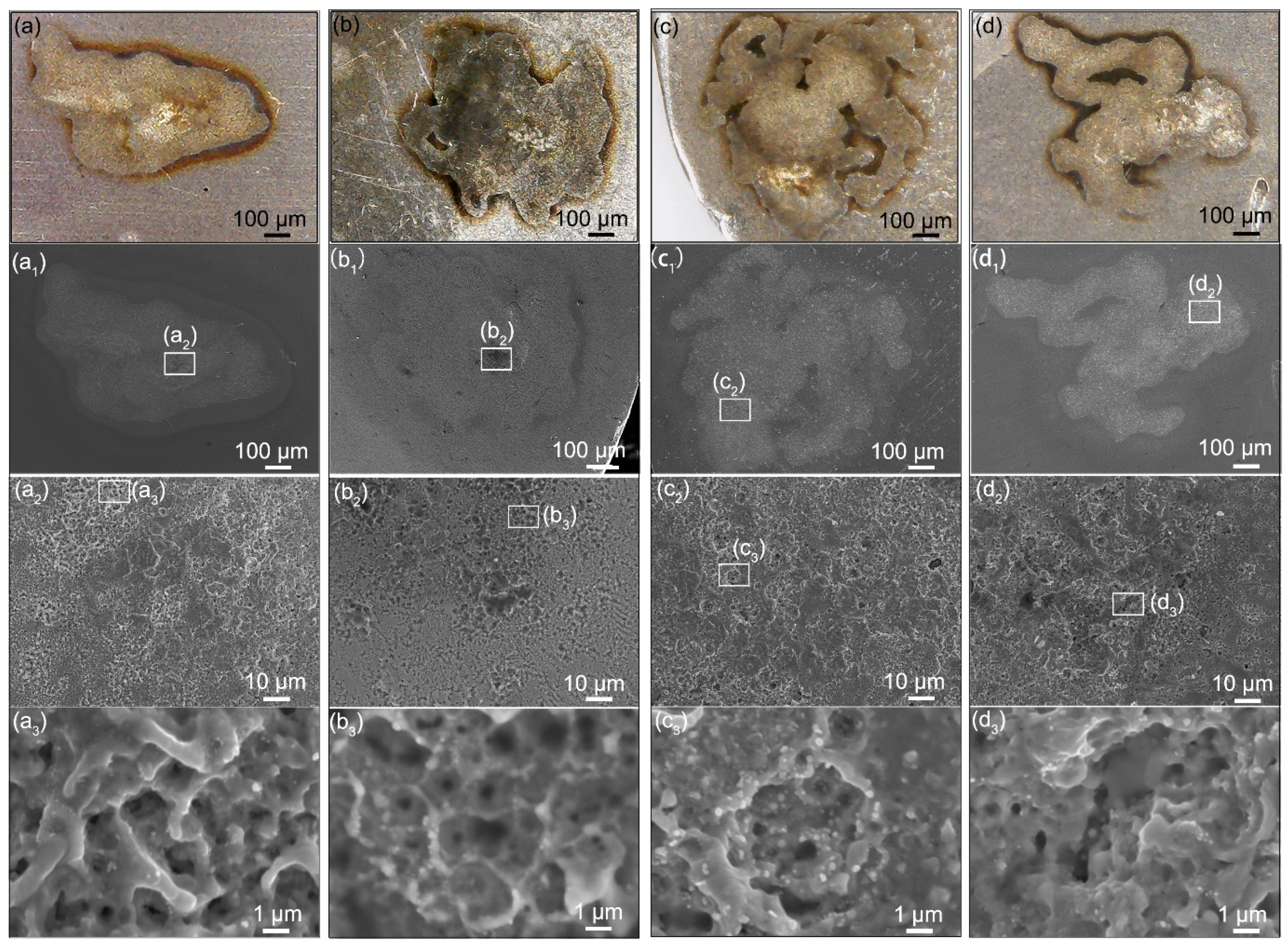
3.3. Microstructure Change after One-Time Arcing Erosion

As the anode approaches or leaves the cathode, electrons generate and escape from the cathode to the anode under an electrical field. During this moving process, electrons bombard gas molecules and metal vapors, producing large amounts of positive ions and electrons. An arc will form once the charged particles reach saturation (Figure S3a) [1]. Then, the positive ions bombard the cathode, resulting in the jet of the cathode material. These materials are transferred to the anode along with the electron flow [42]. The crater and protrusion are the products of this material transfer process (Figure S3b).
The failure of contacts is the result of the gradual worsening of the microstructure. Figure 4 shows the original surface microstructure of Ag/Y2O3 electrical contacts. Spherical Y2O3 particles were distributed in the Ag matrix without pits or pores. However, as shown in Figure 7, an erosion crater (~500 μm) appeared on the cathode after one-time arcing erosion. In the erosion zone, the surface became rough and was covered by smaller ion bombardment craters (<10 μm). For the cathodes prepared with the Y2O3 of 243 nm and 387 nm, these smaller craters connected and formed a continuous network. In contrast, the other two contacts show isolated and deep erosion pits. The microstructure differences determine the mass loss. Generally, the continuous structure indicates rapid arc motion, which may decrease the mass loss. Instead, the isolated and deep erosion pits indicate slow arc motion or even stationary arcing, thereby accelerating the mass loss [5,43]. The results shown in Figure 5 confirmed this relationship.
As mentioned above, the mass transferred from the cathode to the anode upon the arc erosion. Therefore, the anode exhibited a different microstructure change in contrast to the cathode. A protrusion with isolated and larger pores was observed, as shown in Figure 8. Backscattered electron (BSE) images exhibit mainly two phase zones. The bright zone indicates the Ag-rich phase, while the dark area indicates the Y2O3-rich phase. Noticeably, the anodes prepared using 792 nm and 980 nm Y2O3 show coarsened Ag-rich zones and cracks. As mentioned above, the material is transferred from the cathode and deposited on the anode upon the arcing erosion. Meanwhile, the hot electrons bombard the anode, leading to the melting of the anode and thus forming a molten pool. The low-density oxide spheres would float upward and redistribute [44], thereby creating the structure shown in Figure 8(a3–d3). Due to the thermal stress, the cracks formed and propagated in the Y2O3-rich zone. Once the cracks propagated to some extent, spalling occurred, and the mass reduced sharply. Thereby, the failure occurred, as shown in Figure 5. In contrast, the anodes prepared using 243 nm and 387 nm Y2O3 exhibit a relatively uniform microstructure with no coarsened Ag-rich zones. Besides, no cracks are observed. These factors account for the outstanding electrical performances measures, such as the low contact resistance and lower mass loss shown in Figure 5.

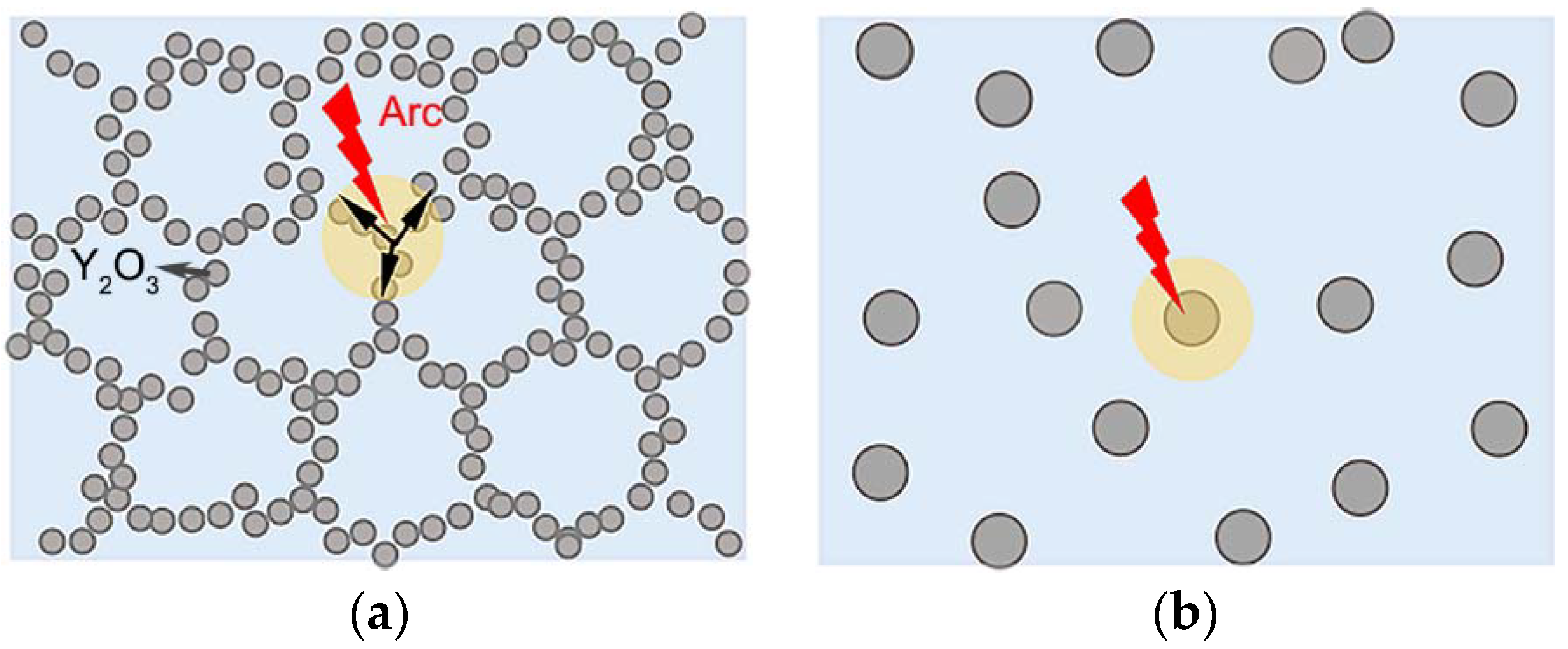
3.4. Mechanism Analysis

From the viewpoint of electrical performances and microstructure, the contact prepared using 243 nm Y2O3 is the best among the four contacts. The differences in Y2O3 size led to the different primitive microstructures. These microstructures changed differently upon arcing erosion. Therefore, the primitive microstructure of contacts is the key factor to determine the subsequent changes in structure and electrical performance.
Y2O3 has a lower work function when compared with Ag [45]. Guan et al. [43,46] noted that the arc movement depends on the distance between the particles of lower work function. Therefore, the Y2O3 particles on the cathode could act as the arc moving sites based on the rule of arc motion. The arc could move along the Y2O3 network if the Y2O3 spacing is small enough, as shown in Figure 9a. If Y2O3 particles are isolated, as shown in Figure 9b, the arc stays around the individual Y2O3 particle, thereby burning the zone around the Y2O3 particle.
As shown in Figure 4, the contact prepared using 243 nm Y2O3 exhibits a quasi-continuous network structure. In this structure, Y2O3 particles are so close to each other that the arc could move along the Y2O3 network. During the rapid moving process, the arc energy releases quickly before extinguishing. Eventually, the shallow and connected erosion craters formed, as shown in Figure 7. If the distances between Y2O3 particles are too far to jump over, the arc would stay and burn the zone around the individual Y2O3 particle, thereby forming isolated and deep erosion pits. Guo et al. [47] pointed out that the fine particles could improve the anti-arc performance by increasing the viscosity of the molten pool. Our work provided a new explanation of particle-size effects on electrical contact performance from the perspective of arc movement.

4. Conclusions

Ag/Y2O3 electrical contacts were successfully obtained based on a low-energy ball milling treatment. Spherical Y2O3 particles were uniformly distributed in the Ag matrix. Changes in Y2O3 particle size at the submicron scale had a remarkable influence on the contacts’ electrical performance. The Ag/Y2O3 contact prepared using 243 nm Y2O3 exhibited the most outstanding performance, including low contact resistance, less mass loss, and long lifetime. The formed quasi-continuous network structure was responsible for the outstanding electrical performances, which significantly improved the anti-arc ability of the electrical contacts.

Supplementary Materials

The following supporting information can be downloaded at: www.mdpi.com/article/10.3390/ma15072450/s1, Figure S1: Schematic of (a) electrical contact test and (b) contact resistance test; Figure S2: SEM images of Ag/Y2O3 mixed powders. The sizes of Y2O3 powders are different: (a,a1) 243 nm, (b,b1) 387 nm, (c,c1) 792 nm, (d,d1) 980 nm; Figure S3: Schematics show the arcing process.

Author Contributions

Conceptualization, S.L., X.S., and R.Y.; methodology, R.Y.; validation, R.Y.; investigation, R.Y.; resources, H.C., H.Y., Z.L., and Y.Z.; data curation, R.Y. and S.L.; writing—original draft preparation, R.Y. and S.L.; writing—review and editing, R.Y., S.L., W.W., and X.S.; visualization, R.Y.; supervision, S.L.; project administration, S.L. and X.S.; funding acquisition, J.C., M.W., X.S., S.L., and M.L. All authors have read and agreed to the published version of the manuscript.

Funding

This research was funded by the Yunnan Key Research and Development Program (202102AB080008, 2018ZE001); the Fundamental Research Funds for the Central Universities (N2002007, N182508026); the National Natural Science Foundation of China (51977027, 51872033, 51967008); and the State Key Laboratory of Advanced Technologies for Comprehensive Utilization of Platinum Metals (SKL-SPM-202014, SKL-SPM-202015, SKL-SPM-202016).

Institutional Review Board Statement

Not applicable.

Informed Consent Statement

Not applicable.

Data Availability Statement

The data presented in this study are available from the corresponding authors upon reasonable request.

Conflicts of Interest

The authors declare no conflict of interest.

References

  1. Slade, P.G. Electrical Contacts: Principles and Applications, 2nd ed.; CRC Press: New York, NY, USA, 2013; pp. 3–943. [Google Scholar]
  2. Zhou, L.; Zhu, S.; Zheng, W.; Li, T.; Wu, L.; Zhang, Z.; Lei, Z. Constant current induction brazing process optimization of AgCdO15-Cu electrical contact. J. Manuf. Process. 2020, 51, 122–129. [Google Scholar] [CrossRef]
  3. Wu, Q.; Xu, G.; Yuan, M.; Wu, C. Influence of operation numbers on arc erosion of Ag/CdO electrical contact materials. IEEE Trans. Compon. Packag. Manuf. Technol. 2020, 10, 845–857. [Google Scholar] [CrossRef]
  4. Wu, X.; Cobbina, S.J.; Mao, G.; Xu, H.; Zhang, Z.; Yang, L. A review of toxicity and mechanisms of individual and mixtures of heavy metals in the environment. Environ. Sci. Pollut. Res. 2016, 23, 8244–8259. [Google Scholar] [CrossRef] [PubMed]
  5. Lin, Z.; Liang, Y.; Zeng, Y.; Chen, X.; Liu, M.; Dai, P.; Chen, J.; Sun, X. Morphology-tunable synthesis and formation mechanism of SnO2 particles and their application in Ag–SnO2 electrical contact materials. Ceram. Int. 2021, 48, 6052–6061. [Google Scholar] [CrossRef]
  6. Li, G.; Ma, Y.; Zhang, X.; Fang, X.; Feng, W. Interface strengthening and fracture characteristics of the Ag-based contact materials reinforced with nanoporous SnO2(Cu, CuO) phases. Appl. Surf. Sci. 2021, 543, 148812. [Google Scholar] [CrossRef]
  7. Chen, S.; Wang, J.; Yuan, Z.; Wang, Z.; Du, D. Microstructure and arc erosion behaviors of Ag-CuO contact material prepared by selective laser melting. J. Alloys Compd. 2021, 860, 158494. [Google Scholar] [CrossRef]
  8. Wang, J.; Kang, Y.; Wang, C.; Wang, J.; Fu, C. Resistance to arc erosion characteristics of CuO skeleton-reinforced Ag-CuO contact materials. J. Alloys Compd. 2018, 756, 202–207. [Google Scholar] [CrossRef]
  9. Guzmán, D.; Aguilar, C.; Rojas, P.; Criado, J.M.; Diánez, M.J.; Espinoza, R.; Guzmán, A.; Martínez, C. Production of Ag−ZnO powders by hot mechanochemical processing. Trans. Nonferrous Met. Soc. China 2019, 29, 365–373. [Google Scholar] [CrossRef]
  10. Wang, D.D.; Tian, W.B.; Ding, J.X.; Ma, A.B.; Zhu, Y.F.; Zhang, P.G.; He, W.; Sun, Z.M. Anisotropic arc erosion resistance of Ag/Ti3AlC2 composites induced by the alignment of Ti3AlC2. Corros. Sci. 2020, 171, 108633. [Google Scholar] [CrossRef]
  11. Ding, J.; Tian, W.; Wang, D.; Zhang, P.; Chen, J.; Zhang, Y.; Sun, Z. Corrosion and degradation mechanism of Ag/Ti3AlC2 composites under dynamic electric arc discharge. Corros. Sci. 2019, 156, 147–160. [Google Scholar] [CrossRef]
  12. Li, H.; Wang, X.; Liu, J.; Zhang, H.; Fei, Y. Effect of electric load characteristics on the arc-erosion behavior of Ag-4 wt.%TiB2-4 wt.%Ni electrical contact material. Appl. Phys. A Mater. Sci. Process. 2021, 127, 433. [Google Scholar] [CrossRef]
  13. Shang, S.; Wang, Z.; Li, W.; Han, C.; Wang, Z. The performance degradation comparison test and failure mechanism of silver metal oxide contact materials. In Proceedings of the 2019 IEEE Holm Conference on Electrical Contacts, Milwaukee, WI, USA, 14–18 September 2019. [Google Scholar]
  14. Hu, B.-L.; Han, J.-Y.; Ge, S.-W.; Hua, X.-J.; Li, S.-L.; Xing, H.-R.; Wang, K.-S.; Hu, P.; Fu, J.-B.; Zhang, W.; et al. Secondary phases strengthening-toughening effects in the Mo–TiC–La2O3 alloys. Mater. Sci. Eng. A 2022, 831, 142271. [Google Scholar] [CrossRef]
  15. Kołacz, D.; Księżarek, S.; Borkowski, P.; Karwan-Baczewska, J.; Lis, M.; Kamińska, M.; Juszczyk, B.; Kulasa, J.; Kowalski, A.; Wierzbicki, Ł.; et al. The Influence of mechanical alloying and plastic consolidation on the resistance to arc erosion of the Ag–Re composite contact material. Materials 2021, 14, 3297. [Google Scholar] [CrossRef] [PubMed]
  16. Safavi, M.S.; Babaei, F.; Ansarian, A.; Ahadzadeh, I. Incorporation of Y2O3 nanoparticles and glycerol as an appropriate approach for corrosion resistance improvement of Ni-Fe alloy coatings. Ceram. Int. 2019, 45, 10951–10960. [Google Scholar] [CrossRef]
  17. Zhang, L.; Yang, J.; Yu, H.; Pan, W. High performance of La-doped Y2O3 transparent ceramics. J. Adv. Ceram. 2020, 9, 493–502. [Google Scholar] [CrossRef]
  18. Li, C.; He, J.; Ma, Y. Sintering behavior and thermal conductivity of Y2O3 fully stabilized HfO2 ceramics. Rare Met. 2021, 40, 1255–1266. [Google Scholar] [CrossRef]
  19. Fu, S.; Xie, M.; Chen, L.; Yang, Y.; Li, Y.; Liu, Y. Ag-SnO2-Y2O3 electrical contact materials prepared by alloy powder pre-oxidation method. Rare Met. 2005, 29, 448–451. [Google Scholar]
  20. Mu, Z.; Geng, H.-R.; Li, M.-M.; Nie, G.-L.; Leng, J.-F. Effects of Y2O3 on the property of copper based contact materials. Compos. Part B Eng. 2013, 52, 51–55. [Google Scholar] [CrossRef]
  21. Yang, R.; Liu, S.; Chen, J.; Cui, H.; Liu, M.; Zhu, F.; Yang, Y.; Xie, M.; Sun, X.; Li, X. Porous Y2O3 fiber-reinforced silver composite exhibiting enhanced mechanical and electrical properties. Ceram. Int. 2019, 45 Pt A, 1881–1886. [Google Scholar] [CrossRef]
  22. Zhang, X.; Xu, Y.; Wang, M.; Liu, E.; Zhao, N.; Shi, C.; Lin, D.; Zhu, F.; He, C. A powder-metallurgy-based strategy toward three-dimensional graphene-like network for reinforcing copper matrix composites. Nat. Commun. 2020, 11, 2775. [Google Scholar] [CrossRef]
  23. Ma, X.; Zhang, Z.-J.; Wang, J.-M.; Sun, S.-H.; Zhang, S.-F.; Yuan, S.; Qiao, Z.-J.; Yu, Z.-Y.; Kang, J.-L.; Li, W.-J. Tuning dual three-dimensional porous copper/graphite composite to achieve diversified utilization of copper current collector for lithium storage. Rare Met. 2021, 40, 2802–2809. [Google Scholar] [CrossRef]
  24. Lin, Z.; Fan, S.; Liu, M.; Liu, S.; Li, J.-G.; Li, J.; Xie, M.; Chen, J.; Sun, X. Excellent anti-arc erosion performance and corresponding mechanisms of a nickel-belt-reinforced silver-based electrical contact material. J. Alloys Compd. 2019, 788, 163–171. [Google Scholar] [CrossRef]
  25. Li, H.; Wang, X.; Hu, Z.; Guo, X. Investigation on arc behavior of AgNi electrical contact material with three-dimensional network structure. Vacuum 2020, 175, 109290. [Google Scholar] [CrossRef]
  26. Wang, Z.; Zhang, X.; Jiang, S.; Qu, Y.; Ou, D.; Wang, J. Arc erosion dynamic of island- and skeleton-restricted microstructure evolution modes in Ag–CuO contact materials. J. Alloys Compd. 2020, 828, 154412. [Google Scholar] [CrossRef]
  27. Salur, E.; Aslan, A.; Kuntoğlu, M.; Acarer, M. Effect of ball milling time on the structural characteristics and mechanical properties of nano-sized Y2O3 particle reinforced aluminum matrix composites produced by powder metallurgy route. Adv. Powder Technol. 2021, 32, 3826–3844. [Google Scholar] [CrossRef]
  28. Toozandehjani, M.; Matori, K.A.; Ostovan, F.; Abdul Aziz, S.; Mamat, M.S. Effect of milling time on the microstructure, physical and mechanical properties of Al-Al2O3 nanocomposite synthesized by ball milling and powder metallurgy. Materials 2017, 10, 1232. [Google Scholar] [CrossRef] [Green Version]
  29. Zhou, D.; Geng, H.; Zeng, W.; Zheng, D.; Pan, H.; Kong, C.; Munroe, P.; Sha, G.; Suryanarayana, C.; Zhang, D. High temperature stabilization of a nanostructured Cu-Y2O3 composite through microalloying with Ti. Mater. Sci. Eng. A 2018, 712, 80–87. [Google Scholar] [CrossRef]
  30. Pradhan, S.K.; Pareek, V.; Panwar, J.; Gupta, S. Synthesis and characterization of ecofriendly silver nanoparticles combined with yttrium oxide (Ag-Y2O3) nanocomposite with assorted adsorption capacity for Cu(II) and Cr(VI) removal: A mechanism perspective. J. Water Process. Eng. 2019, 32, 100917. [Google Scholar] [CrossRef]
  31. Laporte, J.; Fouvry, S.; Alquier, O. Prediction of electrical contact resistance failure of Ag/Ag plated contact subjected to complex fretting-reciprocating sliding. Wear 2017, 376–377, 656–669. [Google Scholar] [CrossRef]
  32. Yang, D.; Liao, G.; Huang, S. Invisible photonic prints shown by UV illumination: Combining photoluminescent and noniridescent structural colors. J. Mater. Chem. C 2019, 7, 11776–11782. [Google Scholar] [CrossRef]
  33. Wu, Q.; Xu, G.; Zhao, C.; Huang, R.; Yuan, M.; Wu, C. Influence of preparation technology on the microstructure and properties of Ag/SnO2Bi2O3CuO composite materials. Mater. Charact. 2022, 183, 111537. [Google Scholar] [CrossRef]
  34. Pfeffer, R.; Dave, R.N.; Wei, D.; Ramlakhan, M. Synthesis of engineered particulates with tailored properties using dry particle coating. Powder Technol. 2001, 117, 40–67. [Google Scholar] [CrossRef]
  35. Kim, W.J.; Lee, T.J.; Han, S.H. Multi-layer graphene/copper composites: Preparation using high-ratio differential speed rolling, microstructure and mechanical properties. Carbon 2014, 69, 55–65. [Google Scholar] [CrossRef]
  36. Huang, X.; Feng, Y.; Li, L.; Li, Z. Erosion behavior of a Cu-Ti3AlC2 cathode by multi-electric arc. Materials 2019, 12, 2947. [Google Scholar] [CrossRef] [Green Version]
  37. Yeheskel, O.; Tevet, O. Elastic Moduli of Transparent Yttria. J. Am. Ceram. Soc. 1999, 82, 136–144. [Google Scholar] [CrossRef]
  38. Greenwood, J.A. Constriction resistance and the real area of contact. Br. J. Appl. Phys. 1966, 17, 1621–1632. [Google Scholar] [CrossRef]
  39. Echeverrigaray, F.G.; de Mello, S.R.S.; Leidens, L.M.; Boeira, C.D.; Michels, A.F.; Braceras, I.; Figueroa, C.A. Electrical contact resistance and tribological behaviors of self-lubricated dielectric coating under different conditions. Tribol. Int. 2020, 143, 106086. [Google Scholar] [CrossRef]
  40. Qiu, D.; Peng, L.; Yi, P.; Lai, X. A micro contact model for electrical contact resistance prediction between roughness surface and carbon fiber paper. Int. J. Mech. Sci. 2017, 124–125, 37–47. [Google Scholar] [CrossRef]
  41. Liu, X.-L.; Cai, Z.-B.; Liu, S.-B.; Peng, J.-F.; Zhu, M.-H. Effect of roughness on electrical contact performance of electronic components. Microelectron. Reliab. 2017, 74, 100–109. [Google Scholar] [CrossRef]
  42. Cui, Y.; Wu, Y.; Niu, C.; Rong, M.; Sun, H.; Niu, L.; Xiong, Q.; Liu, W. Evolution of anodic erosion components and heat transfer efficiency for W and W80Ag20 in atmospheric-pressure arcs. J. Phys. D Appl. Phys. 2020, 53, 475203. [Google Scholar] [CrossRef]
  43. Guan, W.; Yuan, J.; Lv, H.; Zhu, T.; Fang, Y.; Liu, J.; Wang, H.; Li, Z.; Tang, Z.; Yang, W. Homogeneous arc ablation behaviors of CuCr cathodes improved by chromic oxide. J. Mater. Sci. Technol. 2021, 81, 1–12. [Google Scholar] [CrossRef]
  44. Wang, J.; Zhao, H.; Wang, J.; Fu, C.; Chang, Y. Effect of CuO additives on the formation of SnO2-rich layers in Ag-SnO2 materials. J. Alloys Compd. 2019, 770, 920–925. [Google Scholar] [CrossRef]
  45. Yuan, J.; Liu, Y.; Zhu, T.; Long, Y.; Yang, J.; Yao, F.; Chen, D.; Tang, Z. Arc spot formation conditions and influencing factors of a micro multi-electrode technology. J. Phys. D Appl. Phys. 2021, 55, 025203. [Google Scholar] [CrossRef]
  46. Guan, W.; Gao, M.; Lv, H.; Yuan, J.; Chen, D.; Zhu, T.; Fang, Y.; Liu, J.; Wang, H.; Tang, Z.; et al. Laser cladding of layered Zr/Cu composite cathode with excellent arc discharge homogeneity. Surf. Coat. Technol. 2021, 421, 127454. [Google Scholar] [CrossRef]
  47. Guo, X.; Song, K.; Xu, W.; Li, G.; Zhang, Z. Effect of TiB2 particle size on the material transfer behaviour of Cu–TiB2 composites. Mater. Sci. Technol. 2020, 36, 1685–1694. [Google Scholar] [CrossRef]
Figure 1. Schematic diagram of the preparation of Ag/Y2O3 sintered compact.
Materials 15 02450 g001
Figure 2. XRD patterns of Y2O3 spheres, Ag/Y2O3 mixed powder, and Ag/Y2O3 sintered body.
Materials 15 02450 g002
Figure 3. SEM images and size distribution of spherical Y2O3 powders: (a) 243 nm; (b) 387 nm; (c) 792 nm; (d) 980 nm.
Materials 15 02450 g003
Figure 4. (ad) Low- and (a1d1) high-magnification SEM images of Ag/Y2O3 sintered compacts. The mean size of Y2O3 used: (a,a1) 243 nm, (b,b1) 387 nm, (c,c1) 792 nm, (d,d1) 980 nm.
Materials 15 02450 g004
Figure 5. The change in contact resistance (ad) and mass (a1d1) as the cycle number of contact tests increased. The mean size of Y2O3 used: (a,a1) 243 nm, (b,b1) 387 nm, (c,c1) 792 nm, (d,d1) 980 nm.
Materials 15 02450 g005
Figure 6. The morphologies of cathode (ad) and anode (a1d1) after 105 cycle tests. The mean size of Y2O3 used: (a,a1) 243 nm, (b,b1) 387 nm, (c,c1) 792 nm, (d,d1) 980 nm.
Materials 15 02450 g006
Figure 7. Microstructure change of the Ag/Y2O3 cathodes after one-time arcing erosion: (ad) optical images, (a1d1) low-magnification SEM images, (a2d2,a3d3) high-magnification SEM images. The mean size of Y2O3 used: (aa3) 243 nm, (bb3) 387 nm, (cc3) 792 nm, (dd3) 980 nm.
Materials 15 02450 g007
Figure 8. Microstructure changes of the Ag/Y2O3 anodes after one-time arcing erosion: (ad) optical images, (a1d1) low-magnification SEM images, (a2d2) high-magnification SEM images, and (a3d3) backscattered electron (BSE) images. The mean size of Y2O3 used: (aa3) 243 nm, (bb3) 387 nm, (cc3) 792 nm, (dd3) 980 nm.
Materials 15 02450 g008
Figure 9. Arc movement characteristics: (a) moving along the Y2O3 network, (b) staying around the Y2O3 particles.
Materials 15 02450 g009
Table 1. Physical properties of Ag/Y2O3 sintered compacts.
Y2O3 Mean Size
(nm)
Relative Density
(%)
Hardness
(Hv0.1)
Conductivity
(IACS%)
24396.8107.2 ± 3.967.6
38798.1109.2 ± 1.873.0
79296.1105.8 ± 3.469.9
98094.9103.7 ± 2.166.7
Publisher’s Note: MDPI stays neutral with regard to jurisdictional claims in published maps and institutional affiliations.

