
Dimensional Characterization and Hybrid Manufacturing of Copper Parts Obtained by Atomic Diffusion Additive Manufacturing, and CNC Machining

Abstract
:1. Introduction
2. Materials and Methods
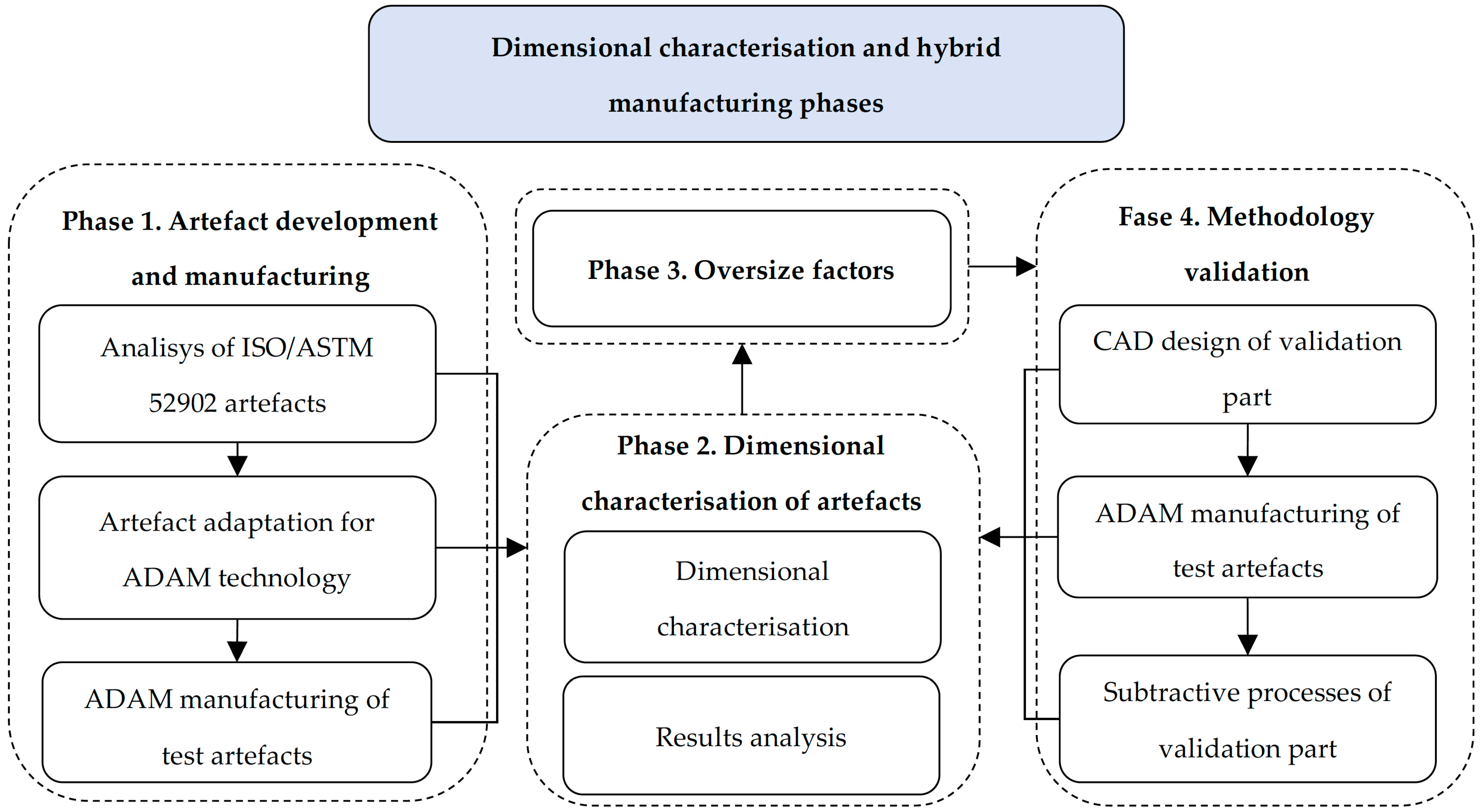
2.1. Overview of the Hybrid Manufacturing Process
2.2. Test Artifacts
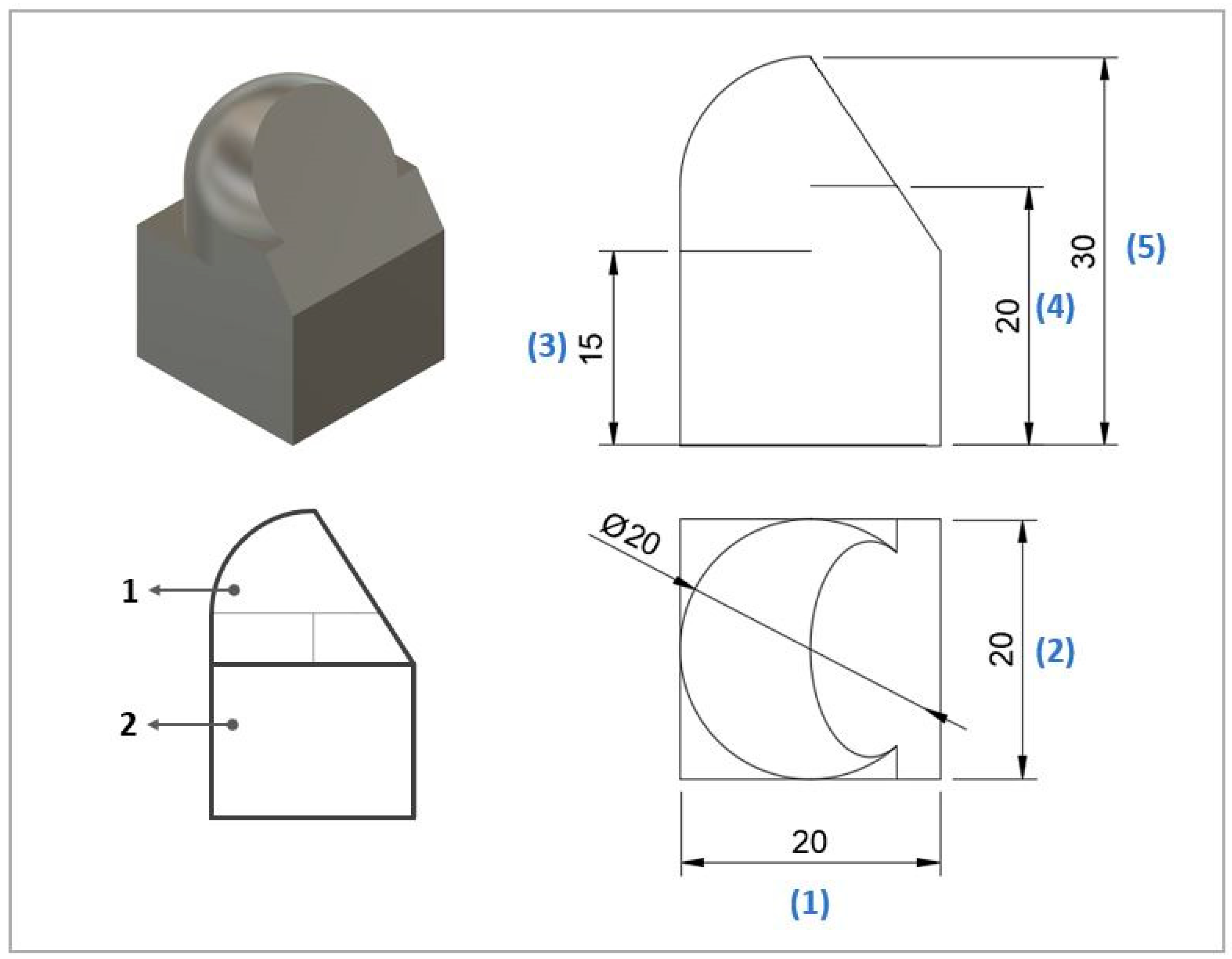
2.3. Validation Specimen
2.4. Materials and ADAM Equipment
2.5. Subtractive Manufacturing
2.6. Dimensional and Roughness Characterization
3. Results
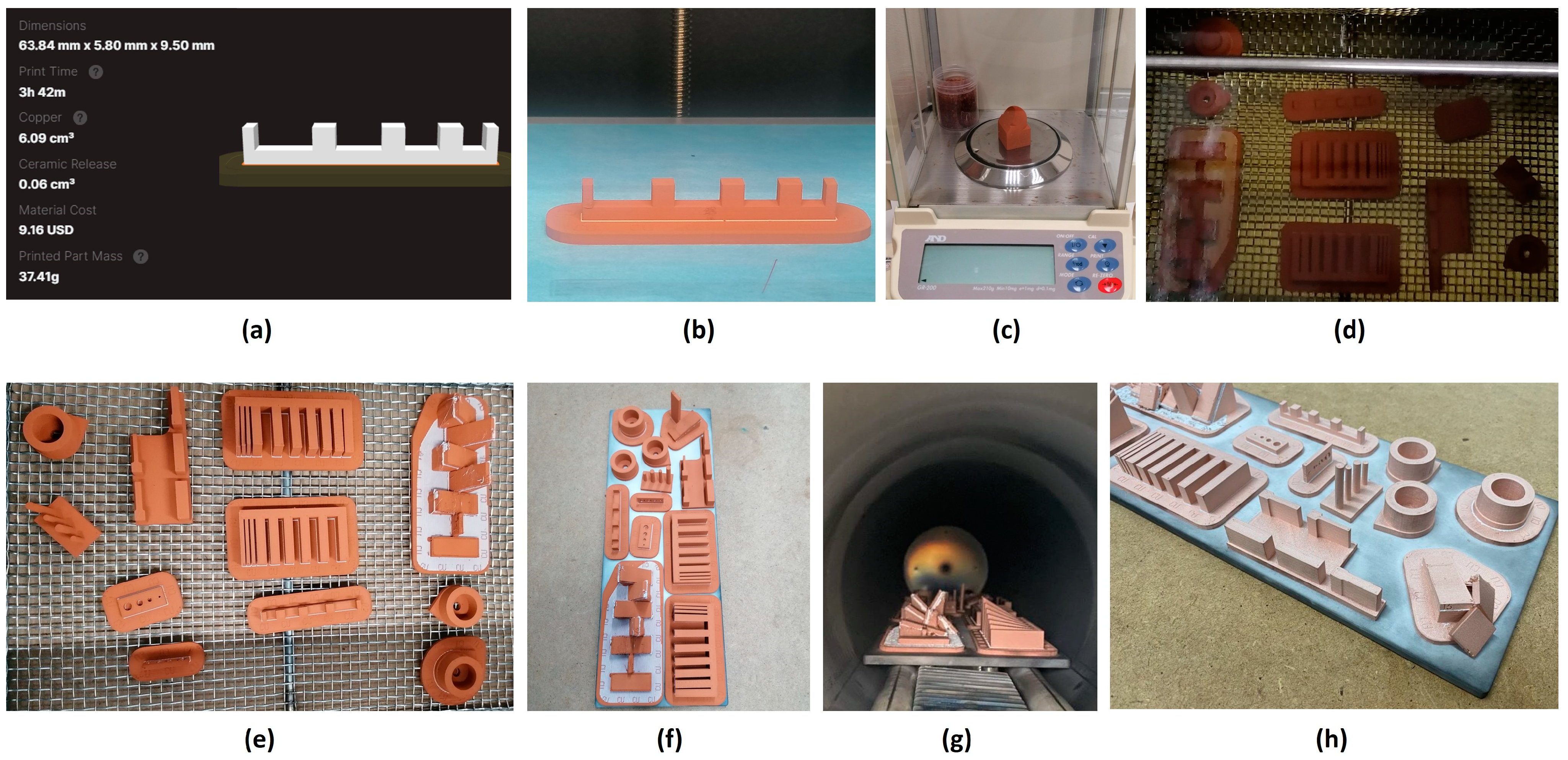
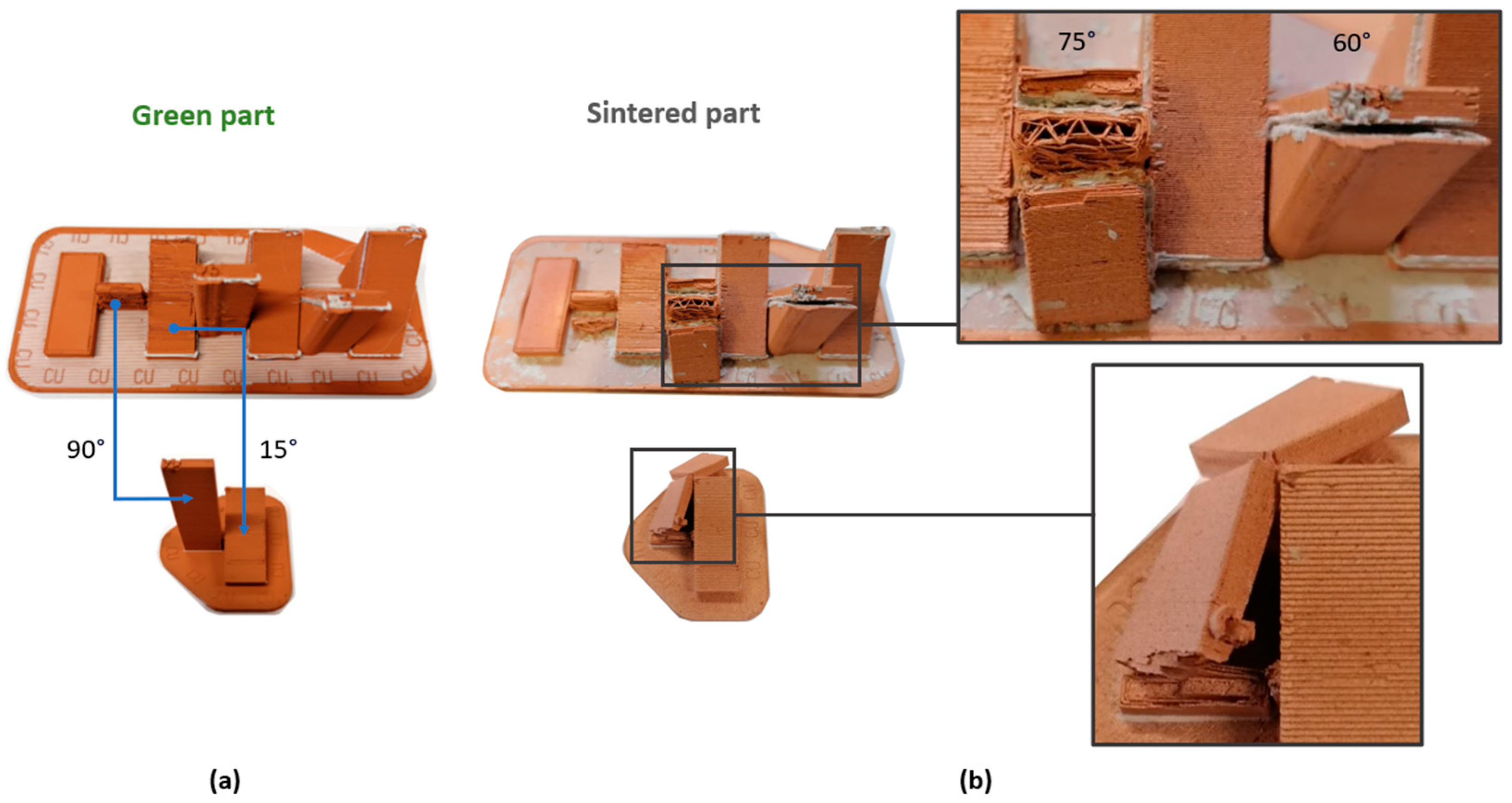
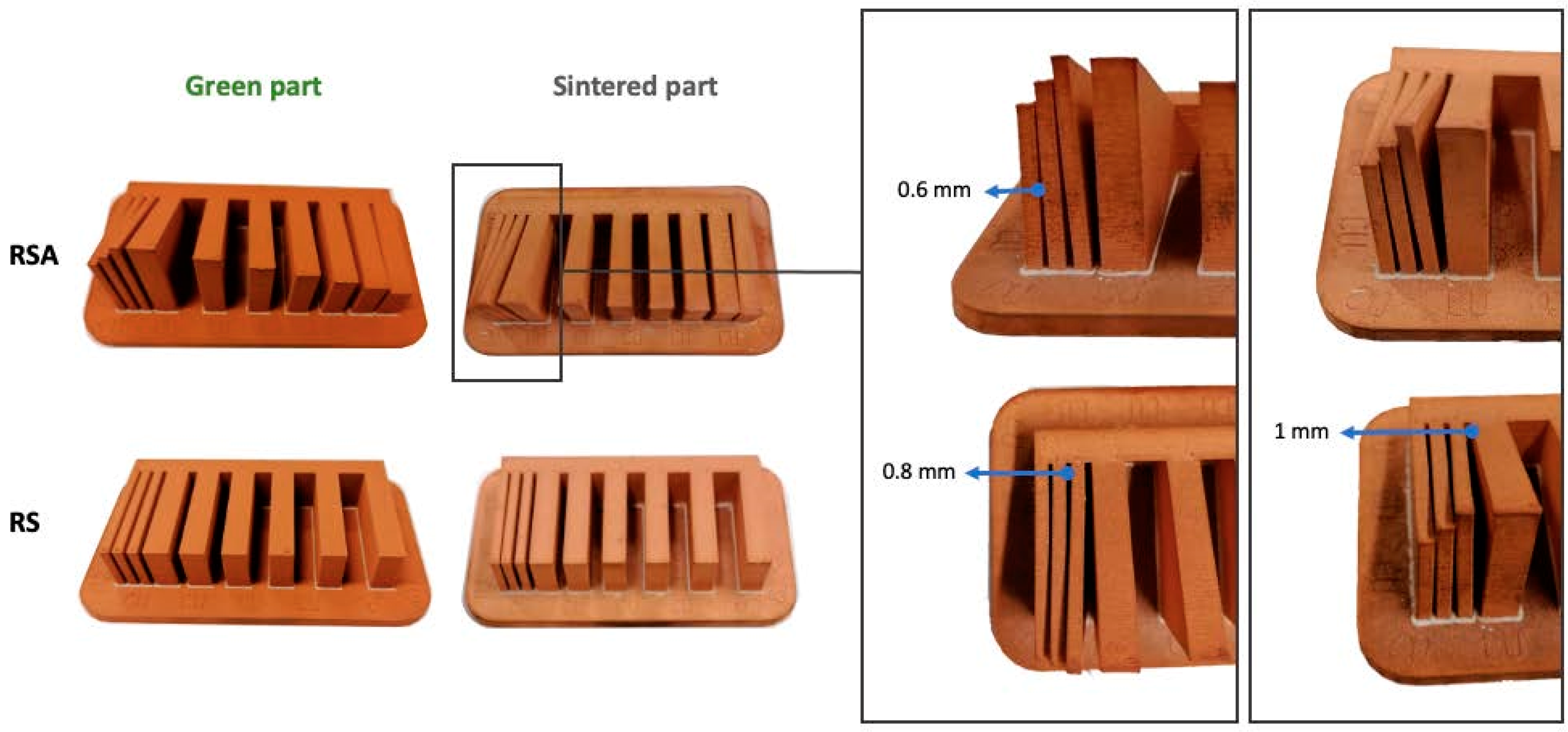
3.1. Manufacturing Defects of the Test Artifacts
3.2. Results of the Dimensional Characterization of the Test Artifacts
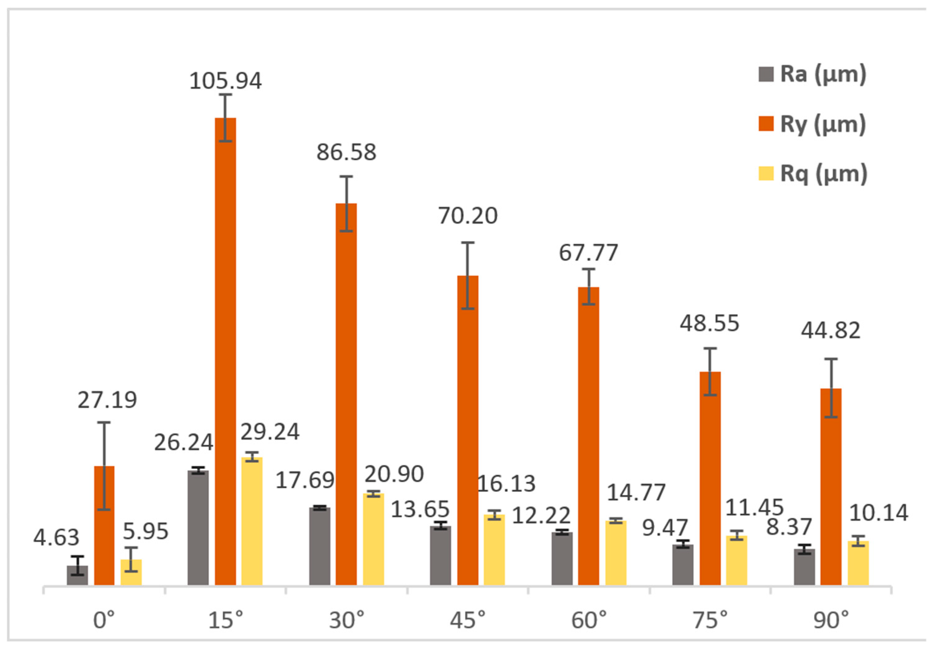
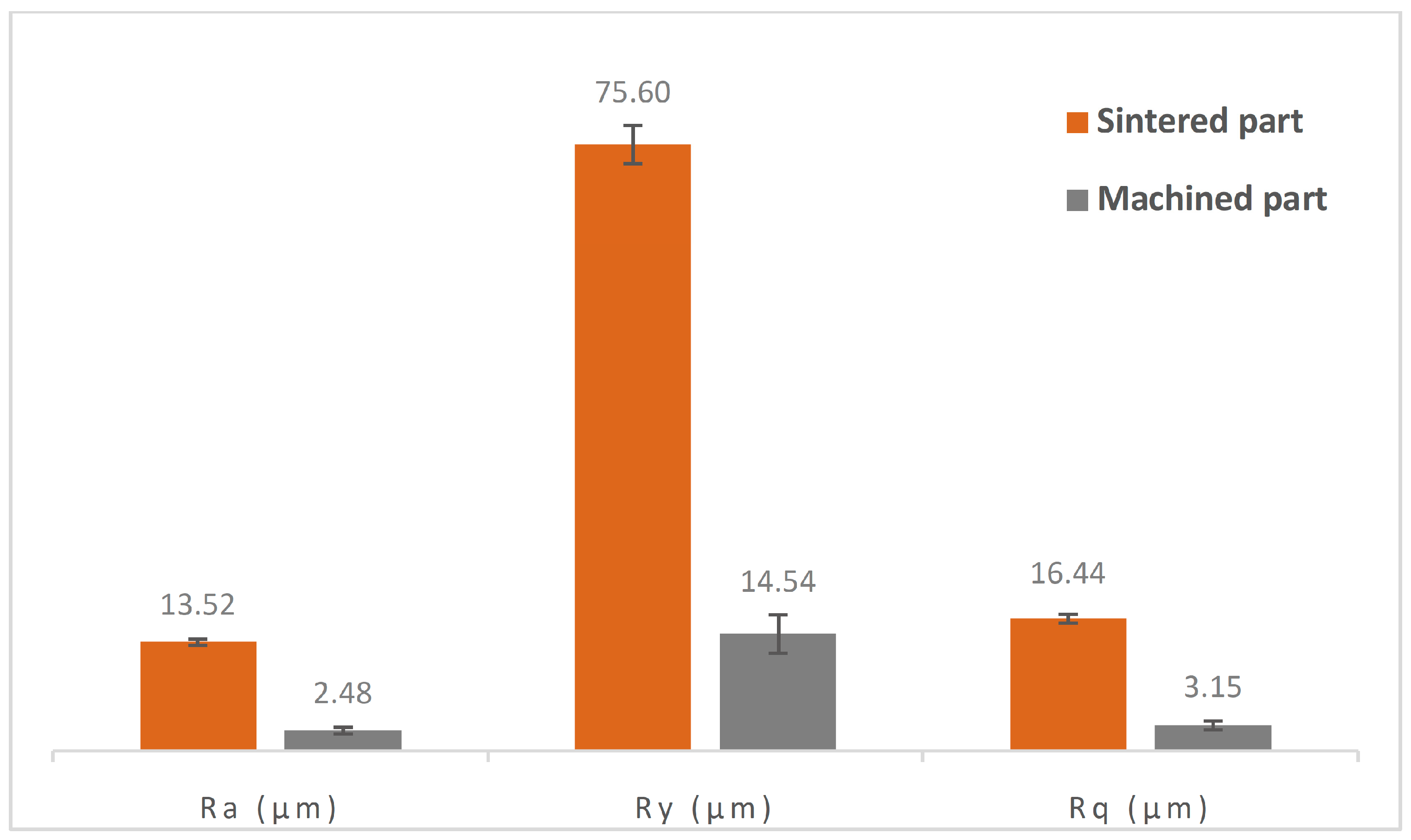
3.3. Results of Surface Texture Characterization
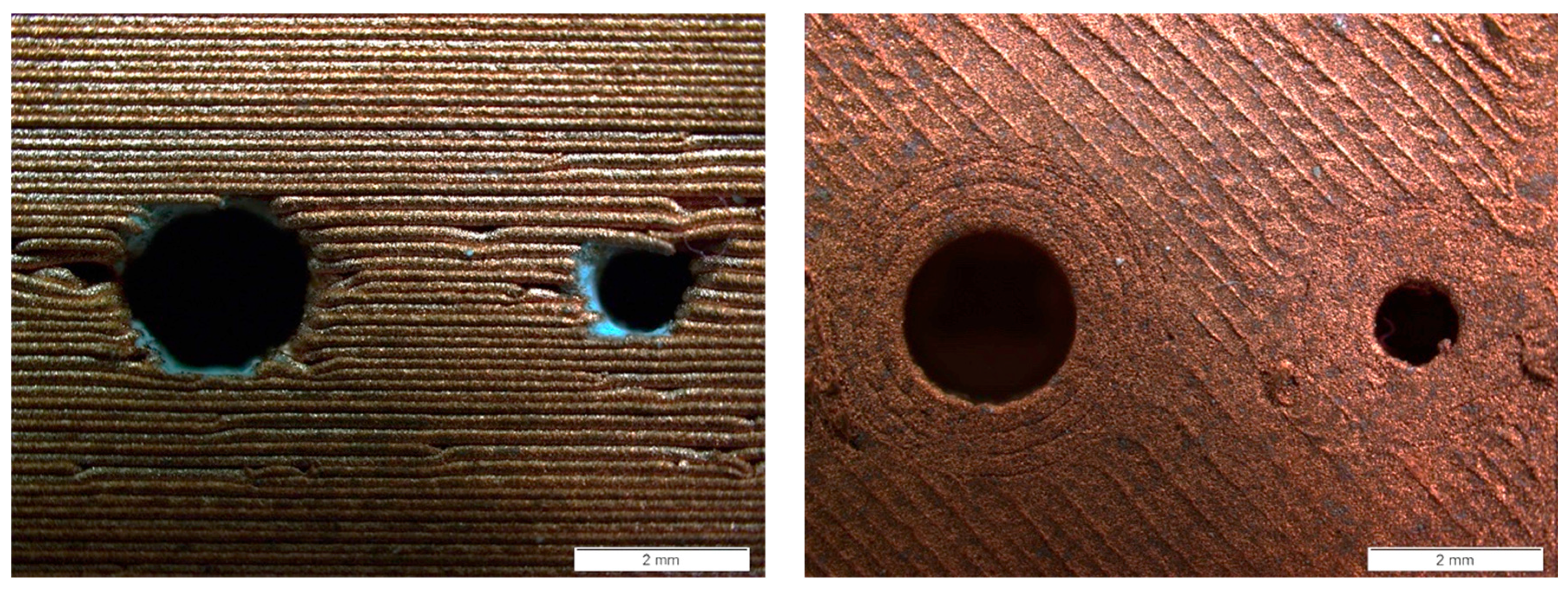
3.4. Analysis of the Manufacturing Orientation of Circular Holes
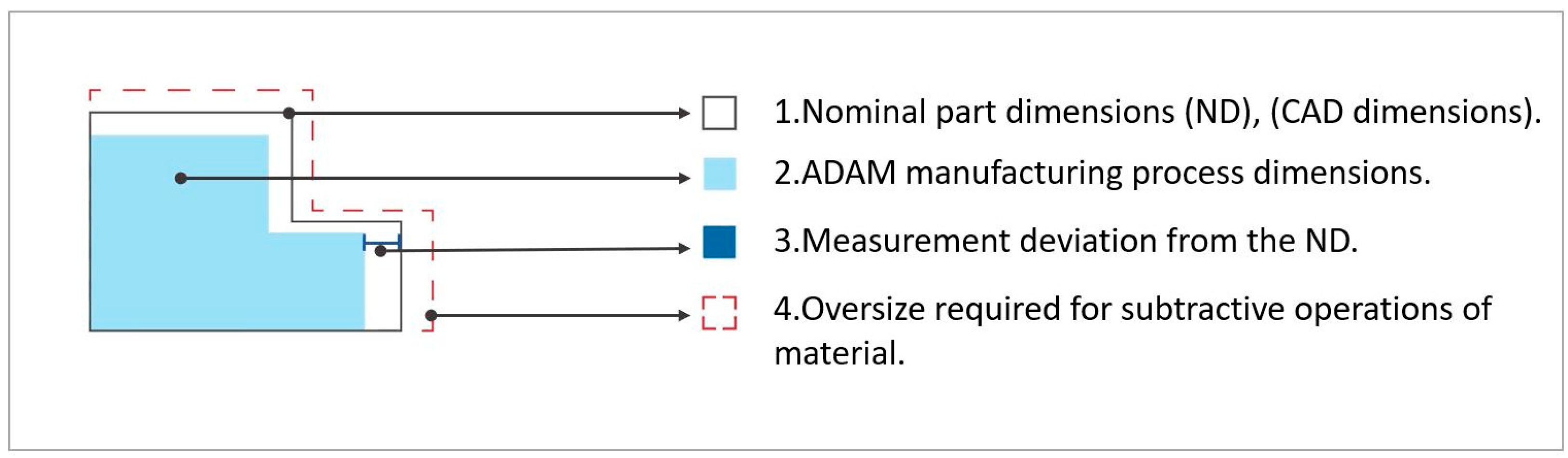
3.5. Analysis of Oversize Factors
3.5.1. Specific Oversize Factor for Cylindrical Geometries
3.5.2. Specific Oversize Factor for Circular Holes
3.5.3. Specific Oversize Factor for Linear Dimensions in the Horizontal Printing Plane (XY Plane)
3.5.4. Specific Oversize Factor for Linear Dimensions in the Vertical Manufacturing Direction (Z)
3.6. Overall Oversize Factor
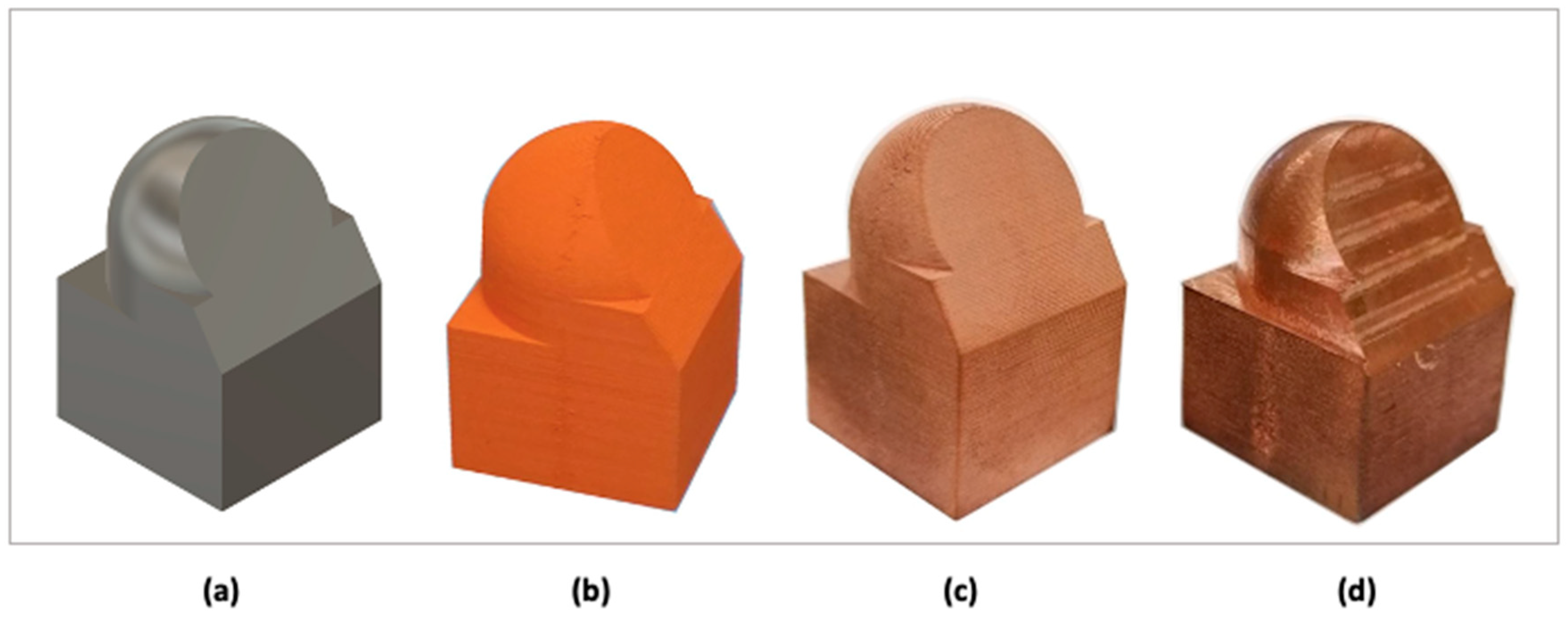
3.7. Validation Specimen Results
4. Conclusions
Supplementary Materials
Author Contributions
Funding
Institutional Review Board Statement
Informed Consent Statement
Data Availability Statement
Conflicts of Interest
References
- Attaran, M. The Rise of 3-D Printing: The Advantages of Additive Manufacturing over Traditional Manufacturing. Bus. Horiz. 2017, 60, 677–688. [Google Scholar] [CrossRef]
- Sgarbossa, F.; Peron, M.; Lolli, F.; Balugani, E. Conventional or Additive Manufacturing for Spare Parts Management: An Extensive Comparison for Poisson Demand. Int. J. Prod. Econ. 2021, 233, 107993. [Google Scholar] [CrossRef]
- Shahar, F.S.; Hameed Sultan, M.T.; Shah, A.U.M.; Azrie Safri, S.N. A Comparative Analysis between Conventional Manufacturing and Additive Manufacturing of Ankle-Foot Orthosis. Appl. Sci. Eng. Prog. 2020, 13, 96–103. [Google Scholar] [CrossRef]
- Jyothish Kumar, L.; Krishnadas Nair, C.G. Current Trends of Additive Manufacturing in the Aerospace Industry. In Advances in 3D Printing and Additive Manufacturing Technologies; Springer: Singapore, 2016. [Google Scholar]
- Rouf, S.; Malik, A.; Singh, N.; Raina, A.; Naveed, N.; Siddiqui, M.I.H.; Haq, M.I.U. Additive Manufacturing Technologies: Industrial and Medical Applications. Sustain. Oper. Comput. 2022, 3, 258–274. [Google Scholar] [CrossRef]
- Germaini, M.M.; Belhabib, S.; Guessasma, S.; Deterre, R.; Corre, P.; Weiss, P. Additive Manufacturing of Biomaterials for Bone Tissue Engineering—A Critical Review of the State of the Art and New Concepts. Prog. Mater. Sci. 2022, 130, 100963. [Google Scholar] [CrossRef]
- Harun, W.S.W.; Kamariah, M.S.I.N.; Muhamad, N.; Ghani, S.A.C.; Ahmad, F.; Mohamed, Z. A Review of Powder Additive Manufacturing Processes for Metallic Biomaterials. Powder Technol. 2018, 327, 128–151. [Google Scholar] [CrossRef]
- Zhao, N.; Parthasarathy, M.; Patil, S.; Coates, D.; Myers, K.; Zhu, H.; Li, W. Direct Additive Manufacturing of Metal Parts for Automotive Applications. J. Manuf. Syst. 2023, 68, 368–375. [Google Scholar] [CrossRef]
- Omiyale, B.O.; Olugbade, T.O.; Abioye, T.E.; Farayibi, P.K. Wire Arc Additive Manufacturing of Aluminium Alloys for Aerospace and Automotive Applications: A Review. Mater. Sci. Technol. 2022, 38, 391–408. [Google Scholar] [CrossRef]
- Idrees, M.; Batool, S.; Din, M.A.U.; Javed, M.S.; Ahmed, S.; Chen, Z. Material-Structure-Property Integrated Additive Manufacturing of Batteries. Nano Energy 2023, 109, 108247. [Google Scholar] [CrossRef]
- Pinilla, S.; Ryan, S.; McKeon, L.; Lian, M.; Vaesen, S.; Roy, A.; Schmitt, W.; Coleman, J.N.; Nicolosi, V. Additive Manufacturing of Li-Ion Batteries: A Comparative Study between Electrode Fabrication Processes. Adv. Energy Mater. 2023, 13, 2203747. [Google Scholar] [CrossRef]
- Thakur, A.; Dong, X. Additive Manufacturing of 3D Structural Battery Composites with Coextrusion Deposition of Continuous Carbon Fibers. Manuf. Lett. 2020, 26, 42–47. [Google Scholar] [CrossRef]
- ISO/ASTM 52900:2021; Additive Manufacturing—General Principles Terminology. ISO: Geneva, Switzerland; ASTM: West Conshohocken, PA, USA, 2021.
- Gong, G.; Ye, J.; Chi, Y.; Zhao, Z.; Wang, Z.; Xia, G.; Du, X.; Tian, H.; Yu, H.; Chen, C. Research Status of Laser Additive Manufacturing for Metal: A Review. J. Mater. Res. Technol. 2021, 15, 855–884. [Google Scholar] [CrossRef]
- Gonzalez-Gutierrez, J.; Cano, S.; Schuschnigg, S.; Kukla, C.; Sapkota, J.; Holzer, C. Additive Manufacturing of Metallic and Ceramic Components by the Material Extrusion of Highly-Filled Polymers: A Review and Future Perspectives. Materials 2018, 11, 840. [Google Scholar] [CrossRef]
- Pragana, J.P.M.; Sampaio, R.F.V.; Bragança, I.M.F.; Silva, C.M.A.; Martins, P.A.F. Hybrid Metal Additive Manufacturing: A State–of–the-Art Review. Adv. Ind. Manuf. Eng. 2021, 2, 100032. [Google Scholar] [CrossRef]
- Capozzi, L.C.; Sivo, A.; Bassini, E. Powder Spreading and Spreadability in the Additive Manufacturing of Metallic Materials: A Critical Review. J. Mater. Process Technol. 2022, 308, 117706. [Google Scholar] [CrossRef]
- Timko, P.; Czánová, T.; Czán, A.; Slabejová, S.; Holubjak, J.; Cedzo, M. Analysis of Parameters of Sintered Metal Components Created by ADAM and SLM Technologies. Manuf. Technol. 2022, 22, 347–355. [Google Scholar] [CrossRef]
- Tosto, C.; Tirillò, J.; Sarasini, F.; Cicala, G. Hybrid Metal/Polymer Filaments for Fused Filament Fabrication (FFF) to Print Metal Parts. Appl. Sci. 2021, 11, 1444. [Google Scholar] [CrossRef]
- Watson, A.; Belding, J.; Ellis, B.D. Characterization of 17-4 PH Processed via Bound Metal Deposition (BMD). In TMS 2020 149th Annual Meeting & Exhibition Supplemental Proceedings; Minerals, Metals and Materials Series; Springer: Berlin/Heidelberg, Germany, 2020. [Google Scholar]
- Bordón, P.; Paz, R.; Monzón, M.D. Evaluation of the Performance of Atomic Diffusion Additive Manufacturing Electrodes in Electrical Discharge Machining. Materials 2022, 15, 5953. [Google Scholar] [CrossRef] [PubMed]
- Galati, M.; Minetola, P. Analysis of Density, Roughness, and Accuracy of the Atomic Diffusion Additive Manufacturing (ADAM) Process for Metal Parts. Materials 2019, 12, 4122. [Google Scholar] [CrossRef] [PubMed]
- Kauffmann, J.; Chemkhi, M.; Gardan, J. Integrated Design and Dimensional Compliance of Bound Powder Extrusion Technology: A Case Study of an Aircraft Engine Bracket. Procedia CIRP 2022, 108, 158–163. [Google Scholar] [CrossRef]
- Turner, B.N.; Gold, S.A. A Review of Melt Extrusion Additive Manufacturing Processes: II. Materials, Dimensional Accuracy, and Surface Roughness. Rapid Prototyp. J. 2015, 21, 250–261. [Google Scholar] [CrossRef]
- Turner, B.N.; Strong, R.; Gold, S.A. A Review of Melt Extrusion Additive Manufacturing Processes: I. Process Design and Modeling. Rapid Prototyp. J. 2014, 20, 192–204. [Google Scholar] [CrossRef]
- Pellegrini, A.; Guerra, M.G.; Lavecchia, F. Shrinkage Evaluation and Geometric Accuracy Assessment on 17–4 PH Samples Made by Material Extrusion Additive Manufacturing. J. Manuf. Process 2024, 109, 394–406. [Google Scholar] [CrossRef]
- Lauwers, B.; Klocke, F.; Klink, A.; Tekkaya, A.E.; Neugebauer, R.; McIntosh, D. Hybrid Processes in Manufacturing. CIRP Ann. Manuf. Technol. 2014, 63, 561–583. [Google Scholar] [CrossRef]
- Jones, J.B. The Synergies of Hybridizing CNC and Additive Manufacturing; Technical Paper—Society of Manufacturing Engineers; Hybrid Manufacturing Technologies Ltd.: Mckinney, TX, USA, 2014; Volume TP14PUB72. [Google Scholar]
- Manogharan, G.; Wysk, R.; Harrysson, O.; Aman, R. AIMS—A Metal Additive-Hybrid Manufacturing System: System Architecture and Attributes. Procedia Manuf. 2015, 1, 273–286. [Google Scholar] [CrossRef]
- Loyda, A.; Arizmendi, M.; Ruiz de Galarreta, S.; Rodriguez-Florez, N.; Jimenez, A. Meeting High Precision Requirements of Additively Manufactured Components through Hybrid Manufacturing. CIRP J. Manuf. Sci. Technol. 2023, 40, 199–212. [Google Scholar] [CrossRef]
- Choi, D.S.; Lee, S.H.; Shin, B.S.; Whang, K.H.; Song, Y.A.; Park, S.H.; Jee, H.S. Development of a Direct Metal Freeform Fabrication Technique Using CO2 Laser Welding and Milling Technology. J. Am. Acad. Dermatol. 2001, 113, 273–279. [Google Scholar] [CrossRef]
- Jeng, J.Y.; Lin, M.C. Mold Fabrication and Modification Using Hybrid Processes of Selective Laser Cladding and Milling. J. Mater. Process Technol. 2001, 110, 98–103. [Google Scholar] [CrossRef]
- Xiong, X.; Zhang, H.; Wang, G. Metal Direct Prototyping by Using Hybrid Plasma Deposition and Milling. J. Mater. Process Technol. 2009, 209, 124–130. [Google Scholar] [CrossRef]
- Minetola, P.; Iuliano, L.; Marchiandi, G. Benchmarking of FDM Machines through Part Quality Using IT Grades. Procedia CIRP 2016, 41, 1027–1032. [Google Scholar] [CrossRef]
- Moylan, S.; Slotwinski, J.; Cooke, A.; Jurrens, K.; Donmez, M.A. Proposal for a Standardized Test Artifact for Additive Manufacturing Machines and Processes. In Proceedings of the 23rd Annual International Solid Freeform Fabrication Symposium—An Additive Manufacturing Conference, SFF 2012, Austin, TX, USA, 6–8 August 2012. [Google Scholar]
- Weaver, J.M.; Barton, T.J.; Linn, J.; Jenkins, D.; Miles, M.P.; Smith, R. Quantifying Accuracy of a Concept Laser Metal Additive Machine through the NIST Test Artifact. Rapid Prototyp. J. 2019, 25, 221–231. [Google Scholar] [CrossRef]
- Mehdi-Souzani, C.; Piratelli-Filho, A.; Anwer, N. Comparative Study for the Metrological Characterization of Additive Manufacturing Artefacts. In Advances on Mechanics, Design Engineering and Manufacturing; Lecture Notes in Mechanical Engineering; Springer: Berlin/Heidelberg, Germany, 2017. [Google Scholar] [CrossRef]
- ISO/ASTM 52902:2019; Additive Manufacturing—Test Artifacts—Geometric Capability Assessment of Additive Manufacturing Systems. ISO: Geneva, Switzerland; ASTM: West Conshohocken, PA, USA, 2019.
- Christodoulou, I.T.; Alexopoulou, V.E.; Karkalos, N.E.; Papazoglou, E.L.; Markopoulos, A.P. On the surface roughness of 3d printed parts with fdm by a low-budget commercial printer. Cut. Tools Technol. Syst. 2022, 65, 52–64. [Google Scholar] [CrossRef]
- Alexopoulou, V.E.; Christodoulou, I.T.; Markopoulos, A.P. Effect of Printing Speed and Layer Height on Geometrical Accuracy of FDM-Printed Resolution Holes of PETG Artifacts. Eng. Proc. 2022, 24, 11. [Google Scholar] [CrossRef]
- Berez, J.; Praniewicz, M.; Saldana, C. Assessing Laser Powder Bed Fusion System Geometric Errors through Artifact-Based Methods. Procedia Manuf. 2021, 53, 395–406. [Google Scholar] [CrossRef]
- Bouaziz, M.A.; Djouda, J.M.; Chemkhi, M.; Rambaudon, M.; Kauffmann, J.; Hild, F. Heat Treatment Effect on 17-4PH Stainless Steel Manufactured by Atomic Diffusion Additive Manufacturing (ADAM). Procedia CIRP 2021, 104, 935–938. [Google Scholar] [CrossRef]
- Raju, N.; Warren, P.; Subramanian, R.; Ghosh, R.; Raghavan, S.; Fernandez, E.; Kapat, J. Material Properties of 17-4PH Stainless Steel Fabricated by Atomic Diffusion Additive Manufacturing (ADAM). In Proceedings of the Solid Freeform Fabrication 2021: Proceedings of the 32nd Annual International Solid Freeform Fabrication Symposium—An additive Manufacturing Conference, Austin, TX, USA, 2–4 August 2021. [Google Scholar]
- Jiang, Q.; Zhang, P.; Yu, Z.; Shi, H.; Wu, D.; Yan, H.; Ye, X.; Lu, Q.; Tian, Y. A Review on Additive Manufacturing of Pure Copper. Coatings 2021, 11, 740. [Google Scholar] [CrossRef]
- Sakib-Uz-Zaman, C.; Khondoker, M.A.H. A Review on Extrusion Additive Manufacturing of Pure Copper. Metals 2023, 13, 859. [Google Scholar] [CrossRef]
- Robinson, J.; Munagala, S.P.; Arjunan, A.; Simpson, N.; Jones, R.; Baroutaji, A.; Govindaraman, L.T.; Lyall, I. Electrical Conductivity of Additively Manufactured Copper and Silver for Electrical Winding Applications. Materials 2022, 15, 7563. [Google Scholar] [CrossRef] [PubMed]
- Uffelmann, S.; Pestotnik, S. Investigation of the Manufacturability of a Copper Coil for Use in Space Components by Means of the Fused Filament Fabrication Process. CEAS Space J. 2023, 15, 701–713. [Google Scholar] [CrossRef]
- Schüßler, P.; Franke, J.; Czink, S.; Antusch, S.; Mayer, D.; Laube, S.; Hanemann, T.; Schulze, V.; Dietrich, S. Characterization of the Metal Fused Filament Fabrication Process for Manufacturing of Pure Copper Inductors. Materials 2023, 16, 6678. [Google Scholar] [CrossRef] [PubMed]
- Constantin, L.; Fan, L.; Pontoreau, M.; Wang, F.; Cui, B.; Battaglia, J.L.; Silvain, J.F.; Lu, Y.F. Additive Manufacturing of Copper/Diamond Composites for Thermal Management Applications. Manuf. Lett. 2020, 24, 61–66. [Google Scholar] [CrossRef]
- Rodriguez, J.; Vicente, J.I.; Ezeiza, J.C.; Zuriarrain, A.; Arrazola, P.J.; Badiola, X.; Dominguez, E.; Soler, D. Mechanical and Electrical Properties of Additively Manufactured Copper. IOP Conf. Ser. Mater. Sci. Eng. 2021, 1193, 012034. [Google Scholar] [CrossRef]
- Markforged Metal 3D Printing Design Guide. Available online: https://3d.markforged.com/white-paper-metal-design-guide.html (accessed on 19 December 2023).
- ISO/ASTM 52902:2023; Additive Manufacturing—Test Artifacts—Geometric Capability Assessment of Additive Manufacturing Systems. ISO: Geneva, Switzerland; ASTM: West Conshohocken, PA, USA, 2023.
- Markforged Copper Material Datasheet Rev 1.0 2-13-2020; Markforged Inc.: Watertown, MA, USA, 2020.
- ISO 21920-2:2021; Geometrical Product Specifications (GPS)—Surface Texture: Profile—Part 2: Terms, Definitions and Surface Texture Parameters. ISO: Geneva, Switzerland, 2021.
- Haidiezul, A.H.M.; Aiman, A.F.; Bakar, B. Surface Finish Effects Using Coating Method on 3D Printing (FDM) Parts. In Proceedings of the IOP Conference Series: Materials Science and Engineering; IOP Publishing: Bristol, UK, 2018; Volume 318. [Google Scholar]
- Boschetto, A.; Bottini, L.; Veniali, F. Finishing of Fused Deposition Modeling Parts by CNC Machining. Robot. Comput. Integr. Manuf. 2016, 41, 92–101. [Google Scholar] [CrossRef]


| Artifact Nomenclature and Dimensional Purpose | Original Artifact | ADAM Manufacturing Feasibility | Modified Artifact | Justification for Modification | Measured Dimensions | ||
|---|---|---|---|---|---|---|---|
| Fine Grade (F) | Medium Grade (M) | Coarse Grade (C) | |||||
| Lineal artifact (LA) Precision of linear positioning along a machine axis is assessed. |  | Non-existent 1 | Yes | Non-existent 1 |  | No modifications were applied. | -Position of the cube faces with respect to a part edge. Length of the part contour 3. |
| Circular artifact (CA) Dynamic precision is studied to project the activation energy or the method of joining material onto the manufacturing surface in the AM machine. |  | Partially | Partially | No 2 |  | Removal of the inner ring due to a thickness below the minimum compatible with ADAM technology. | -Inner and outer ring diameters. Inner hole, base. |
| Resolution pin (RP) The ability of an AM system or material to produce fine features with different aspect ratios is analyzed. |  | No | No | Partially |  | Removal of pins with diameters or lengths below ADAM technology limits and consolidation of M and C grades into a single artifact. | -Diameters of the pins. -Pin heights. -Length of the part contour 3. |
| Resolution hole (RH) The minimum size of the internal cylindrical feature achievable at different aspect ratios is analyzed. | 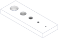 | No | No | Partially | 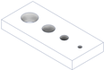 | Removal of holes with diameters below the limits of ADAM technology. | -Diameters of the holes. -Length of the part contour 3. |
| Resolution rib (RR) The minimum thickness achievable by an AM system is examined. | 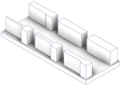 | No | No | Partially |  | Rib removal with dimensions below ADAM technology limits. | -Thickness of the rib. -Rib height. -Length of the part contour 3. |
| Resolution slot (RS) The minimum dimension of a slot or the minimum spacing between components is assessed. | 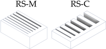 | No | Partially | Partially | 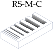 | Removal of grooves with widths below the limits of ADAM technology and consolidation of M and C grades into a single artifact. | -Slot width. -Length of the part contour 3. |
| Resolution slot with angularity (RSA) The minimum dimension of a slot or the minimum spacing between components is assessed. | 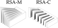 | No | Partially | Partially |  | Removal of grooves with widths below the limits of ADAM technology and consolidation of M and C grades into a single artifact. | -Slot width. -Length of the part contour 3. |
| Surface texture (ST) Surface texture of elements manufactured by AM systems is studied. |  | No | Yes | Yes |  | Given the adequacy of the medium grade, the coarse grade was not taken into consideration. No modifications were applied. | -Mean surface roughness. |
| Operation | Area | Geometric Data | Spindle Speed (rpm) | Feed Rate (mm/min) | Stepover (mm) | Direction | Depth (mm) Roughing/Finishing |
|---|---|---|---|---|---|---|---|
| Facing | Inclined surface | 15 mm height | 2000 | 30 | 4.2 | Climb milling | 0.5/0.1 |
| 2D contouring | Cylindrical surface | 5 mm height | 5000 | 30 | - | Climb milling | 2.0/0.1 |
| Spirals | Spherical surface | Up to 45° angle | 4000 | 100 | 0.1 | Climb-conventional | -/0.6 |
| 3D contouring | Spherical surface | From 45° angle | 4000 | 100 | 0.1 | Climb milling | -/0.1 |
| Greeen Part | Sintered Part | |||||||
|---|---|---|---|---|---|---|---|---|
| Dimensional Deviation (mm) | Percentage Deviation (%) | Dimensional Deviation (mm) | Percentage Deviation (%) | |||||
| Mean | SD | Mean | SD | Mean | SD | Mean | SD | |
| Circular artifact | ||||||||
| Solid without raft | 2.683 | 1.336 | 16.14 | 1.17 | 0.056 | 0.122 | 0.81 | 1.20 |
| Solid with raft | 2.691 | 1.384 | 15.96 | 0.62 | 0.130 | 0.063 | 1.37 | 1.56 |
| Non-solid without raft | 2.681 | 1.391 | 15.87 | 0.55 | −0.027 | 0.051 | 0.05 | 0.60 |
| Resolution hole | ||||||||
| Horizontal orientation | 0.464 | 0.230 | 18.55 | 1.39 | 0.090 | 0.035 | 4.07 | 1.54 |
| Vertical orientation | n/a | n/a | n/a | n/a | 0.109 | 0.060 | 5.04 | 3.20 |
| Resolution slot | ||||||||
| Without angularity | ||||||||
| Coarse grade | 0.642 | 0.295 | 19.44 | 2.80 | 0.140 | 0.051 | 4.64 | 1.78 |
| Medium grade 1 | 0.205 | 0.040 | 25.92 | 0.064 | 0.042 | 0.126 | 3.61 | 17.58 |
| With angularity | ||||||||
| Coarse grade | 0.683 | 0.334 | 20.15 | 0.064 | 0.143 | 0.131 | 2.62 | 4.84 |
| Medium grade 1 | 0.246 | 0.045 | 31.19 | 2.59 | 0.059 | 0.454 | 0.33 | 50.06 |
| Resolution rib | ||||||||
| Thickness | 0.550 | 0.248 | 13.44 | 1.09 | −0.030 | 0.016 | −1.00 | 0.85 |
| Height | 1.827 | 0.020 | 18.27 | 0.20 | 0.148 | 0.065 | 1.48 | 0.65 |
| Lineal artifact | ||||||||
| Face-to-face distance | 4.350 | 3.039 | 15.01 | 2.05 | 0.224 | 0.248 | 0.15 | 1.71 |
| Resolution pin | ||||||||
| Diameter | 0.317 | 0.095 | 8.91 | 1.28 | −0.155 | 0.015 | −4.56 | 1.04 |
| Height | 3.269 | 0.966 | 18.66 | 0.35 | 0.464 | 0.154 | 2.64 | 0.21 |
| Sintered Part | ||||
|---|---|---|---|---|
| Dimensional Deviation (mm) | Percentage Deviation (%) | |||
| Mean | SD | Mean | SD | |
| Circular artifact | ||||
| Solid without raft | 0.098 | 0.079 | 0.97 | 1.02 |
| Non-solid without raft | 0.050 | 0.011 | 0.42 | 0.36 |
| Resolution slot | ||||
| Without angularity | ||||
| Medium grade | 0.100 | 0.058 | 13.3 | 7.80 |
| With angularity | ||||
| Coarse grade | 0.167 | 0.090 | 5.03 | 1.14 |
| Medium grade 1 | 0.328 | 0.223 | 38.3 | 17.24 |
| Lineal artifact | ||||
| Face-to-face distance | 0.266 | 0.195 | 1.22 | 1.12 |
| Artifacts and Geometries | Nominal Dimension (mm) | Mean Measurement (mm) | Dimensional Deviation (mm) | Percent Deviation (%) | |||
|---|---|---|---|---|---|---|---|
| Mean | SD | Mean | SD | Mean | SD | ||
| Circular artifact without raft | |||||||
| Cylinder outer diameter | 23.5 | 23.502 | 0.036 | 0.002 | 0.036 | 0.01 | 0.15 |
| Base outer diameter | 25.0 | 24.916 | 0.026 | −0.084 | 0.026 | −0.34 | 0.10 |
| Circular artifact with raft | |||||||
| Cylinder outer diameter | 23.5 | 23.559 | 0.017 | 0.059 | 0.017 | 0.25 | 0.07 |
| Base outer diameter | 25.0 | 25.096 | 0.036 | 0.096 | 0.036 | 0.38 | 0.14 |
| Resolution pin | |||||||
| Ratio 6:1 y Ø 4 mm | 4.0 | 3.867 | 0.019 | −0.133 | 0.019 | −3.33 | 0.47 |
| Ratio 6:1 y Ø 3 mm | 3.0 | 2.835 | 0.009 | −0.165 | 0.009 | −5.51 | 0.30 |
| Ratio 4:1 y Ø 4 mm | 4.0 | 3.837 | 0.012 | −0.163 | 0.012 | −4.08 | 0.29 |
| Ratio 4:1 y Ø 3 mm | 3.0 | 2.840 | 0.017 | −0.160 | 0.017 | −5.34 | 0.58 |
| Mean deviation of larger cylinders | 0.018 | 0.029 | 0.08 | 0.12 | |||
| Maximum deviation of larger cylinders | 0.096 | 0.036 | 0.38 | 0.14 | |||
| Mean deviation of smaller cylinders | −0.155 | 0.014 | −4.57 | 0.41 | |||
| Maximum deviation of smaller cylinders | −0.165 | 0.019 | −5.51 | 0.30 | |||
| Mean global deviation | −0.069 | 0.022 | −2.24 | 0.26 | |||
| Artifacts and Geometries | Nominal Dimension (mm) | Mean Measurement (mm) | Dimensional Deviation (mm) | Percent Deviation (%) | |||
|---|---|---|---|---|---|---|---|
| Mean | SD | Mean | SD | Mean | SD | ||
| Circular artifact without raft | |||||||
| Cylinder outer diameter | 15.0 | 15.192 | 0.048 | 0.192 | 0.048 | 1.28 | 0.32 |
| Base hole diameter | 5.0 | 5.114 | 0.011 | 0.114 | 0.011 | 2.28 | 0.22 |
| Circular artifact with raft | |||||||
| Cylinder outer diameter | 15.0 | 15.184 | 0.028 | 0.184 | 0.028 | 1.23 | 0.18 |
| Base hole diameter | 5.0 | 5.180 | 0.012 | 0.180 | 0.012 | 3.61 | 0.23 |
| Resolution hole | |||||||
| Diameter 4 mm | 4.0 | 4.081 | 0.012 | 0.081 | 0.012 | 2.04 | 0.29 |
| Diameter 3 mm | 3.0 | 3.120 | 0.004 | 0.120 | 0.004 | 4.01 | 0.13 |
| Diameter 2 mm | 2.0 | 2.115 | 0.008 | 0.115 | 0.008 | 5.74 | 0.40 |
| Diameter 1 mm | 1.0 | 1.045 | 0.020 | 0.045 | 0.020 | 4.48 | 2.00 |
| Maximum deviation | 0.192 | 0.048 | 5.74 | 0.40 | |||
| Mean global deviation | 0.129 | 0.018 | 3.08 | 0.47 | |||
| Artifacts and Geometries | Nominal Dimension (mm) | Mean Measurement (mm) | Dimensional Deviation (mm) | Percent Deviation (%) | |||
|---|---|---|---|---|---|---|---|
| Mean | SD | Mean | SD | Mean | SD | ||
| Resolution hole | |||||||
| Length horizontal orientation (axis X) | 22.5 | 22.489 | 0.011 | −0.011 | 0.011 | −0.05 | 0.05 |
| Length horizontal orientation (axis Y) | 10 | 9.913 | 0.025 | −0.087 | 0.025 | −0.87 | 0.25 |
| Resolution slot without angle | |||||||
| Length (axis X) | 58.4 | 58.869 | 0.101 | 0.469 | 0.101 | 0.80 | 0.17 |
| Length (axis Y) | 30 | 30.205 | 0.157 | 0.205 | 0.157 | 0.68 | 0.52 |
| Resolution rib | |||||||
| Length (axis X) | 72 | 73.073 | 0.142 | 1.073 | 0.142 | 1.49 | 0.20 |
| Length (axis Y) | 28.5 | 28.794 | 0.047 | 0.294 | 0.047 | 1.03 | 0.16 |
| Lineal artifact | |||||||
| Length (axis X) | 55 | 55.489 | 0.013 | 0.489 | 0.013 | 0.89 | 0.02 |
| Length (axis Y) | 5 | 4.874 | 0.015 | −0.126 | 0.015 | −2.52 | 0.30 |
| Resolution pin | |||||||
| Length (axis X) | 28 | 28.258 | 0.022 | 0.258 | 0.022 | 0.92 | 0.08 |
| Length (axis Y) | 18 | 18.156 | 0.033 | 0.156 | 0.033 | 0.87 | 0.18 |
| Circular artifact without raft | |||||||
| Base outer diameter (axis X,Y) | 25 | 24.916 | 0.026 | −0.084 | 0.026 | −0.34 | 0.10 |
| Circular artifact with raft | |||||||
| Base outer diameter (axis X,Y) | 25 | 25.096 | 0.036 | 0.096 | 0.036 | 0.38 | 0.14 |
| Maximum deviation | 1.073 | 0.157 | −2.52 | 0.30 | |||
| Mean global deviation | 0.228 | 0.052 | 0.27 | 0.18 | |||
| Artifacts and Geometries | Nominal Dimension (mm) | Mean Measurement (mm) | Dimensional Deviation (mm) | Percentage Deviation (%) | |||
|---|---|---|---|---|---|---|---|
| Mean | SD | Mean | SD | Mean | SD | ||
| Lineal artifact | |||||||
| Artifact height | 8.0 | 8.151 | 0.043 | 0.151 | 0.043 | 1.89 | 0.53 |
| Circular artifact without raft | |||||||
| Artifact height | 13.0 | 13.289 | 0.035 | 0.289 | 0.035 | 2.22 | 0.27 |
| Circular artifact with raft | |||||||
| Artifact height | 13.0 | 13.181 | 0.052 | 0.181 | 0.052 | 1.39 | 0.40 |
| Resolution hole | |||||||
| Height of artifact with horizontal orientation | 2.5 | 2.862 | 0.048 | 0.362 | 0.048 | 14.48 * | 1.90 |
| Height of artifact with vertical orientation | 10.0 | 10.194 | 0.022 | 0.194 | 0.022 | 1.94 | 0.22 |
| Resolution slot without angle | |||||||
| Artifact height | 10.0 | 10.171 | 0.047 | 0.171 | 0.047 | 1.71 | 0.47 |
| Resolution rib | |||||||
| Height (6 mm thickness) | 10.0 | 10.095 | 0.023 | 0.095 | 0.023 | 0.95 | 0.23 |
| Height (5 mm thickness) | 10.0 | 10.097 | 0.041 | 0.097 | 0.041 | 0.97 | 0.41 |
| Height (4 mm thickness) | 10.0 | 10.110 | 0.032 | 0.110 | 0.032 | 1.10 | 0.32 |
| Height (3 mm thickness) | 10.0 | 10.219 | 0.035 | 0.219 | 0.035 | 2.19 | 0.35 |
| Height (2 mm thickness) | 10.0 | 10.218 | 0.037 | 0.218 | 0.037 | 2.18 | 0.37 |
| Height plus base | 13.0 | 13.342 | 0.047 | 0.342 | 0.047 | 2.63 | 0.36 |
| Resolution pin | |||||||
| Pin height (6:1 y Ø 4 mm) | 24.0 | 24.682 | 0.072 | 0.682 | 0.072 | 2.84 | 0.30 |
| Pin height (6:1 y Ø 3 mm) | 18.0 | 18.454 | 0.037 | 0.454 | 0.037 | 2.52 | 0.21 |
| Pin height (4:1 y Ø 4 mm) | 16.0 | 16.384 | 0.041 | 0.384 | 0.041 | 2.40 | 0.25 |
| Pin height (4:1 y Ø 3 mm) | 12.0 | 12.334 | 0.042 | 0.334 | 0.042 | 2.78 | 0.35 |
| Maximum deviation | 0.682 | 0.072 | 2.84 | 0.30 | |||
| Mean global deviation | 0.261 | 0.041 | 1.98 | 0.34 | |||
| Geometry Type | Oversize Factors | Global Factor 2 | Minimum Oversize (mm) | Maximum Oversize (mm) | ||
|---|---|---|---|---|---|---|
| Specific (%) | Clamping (%) | Machining 1 (mm) | ||||
| Major cylinders | 0.5 | 1.0 | 0.25 | 1.5% + 0.5 mm | 0.85 | 0.88 |
| Minor cylinders | 6.0 | 1.0 | 0.25 | 7% + 0.5 mm | 0.71 | 0.78 |
| Circular holes | −0.2 mm | −0.2 mm | −0.15 | −0.70 mm | −0.70 | −0.70 |
| Linear horizontal plane | 0.0 | 1.0 | 0.25 | 1% + 0.5 mm | 0.73 | 1.22 |
| Linear vertical direction | 0.0 | 1.0 | 0.25 | 1% + 0.5 mm | 0.53 | 0.74 |
| Global (average) 3 | 0.71 | 0.91 | ||||
| Dimension 1 | Nominal Dimension (mm) | Oversize (mm) | Expected Dimension 2 (mm) | Sintered Part | Hybrid Manufacturing | |||||
|---|---|---|---|---|---|---|---|---|---|---|
| Measurement (mm) | Deviation from Expected Dimension (mm) | Measurement (mm) | Dimensional Deviation 3 (mm) | |||||||
| Mean | SD | Mean | SD | Mean | SD | |||||
| 1 | 20.0 | 1.20 | 21.20 | 21.35 | 0.04 | 0.15 | 0.02 | n/a | n/a | n/a |
| 2 | 20.0 | 1.20 | 21.20 | 21.38 | 0.07 | 0.18 | 0.02 | 20.04 | 0.02 | 0.04 |
| 3 | 15.0 | 1.15 | 16.15 | 15.87 | 0.04 | −0.28 | 0.01 | 15.08 | 0.06 | 0.08 |
| 4 | 20.0 | 1.20 | 21.20 | 21.19 | 0.15 | −0.01 | 0.09 | 20.04 | 0.06 | 0.04 |
| 5 | 30.0 | 1.30 | 31.30 | 31.98 | 0.05 | 0.68 | 0.02 | 30.09 | 0.01 | 0.09 |
Disclaimer/Publisher’s Note: The statements, opinions and data contained in all publications are solely those of the individual author(s) and contributor(s) and not of MDPI and/or the editor(s). MDPI and/or the editor(s) disclaim responsibility for any injury to people or property resulting from any ideas, methods, instructions or products referred to in the content. |
© 2024 by the authors. Licensee MDPI, Basel, Switzerland. This article is an open access article distributed under the terms and conditions of the Creative Commons Attribution (CC BY) license (https://creativecommons.org/licenses/by/4.0/).
Share and Cite
Monzón, E.; Bordón, P.; Paz, R.; Monzón, M. Dimensional Characterization and Hybrid Manufacturing of Copper Parts Obtained by Atomic Diffusion Additive Manufacturing, and CNC Machining. Materials 2024, 17, 1437. https://doi.org/10.3390/ma17061437
Monzón E, Bordón P, Paz R, Monzón M. Dimensional Characterization and Hybrid Manufacturing of Copper Parts Obtained by Atomic Diffusion Additive Manufacturing, and CNC Machining. Materials. 2024; 17(6):1437. https://doi.org/10.3390/ma17061437
Chicago/Turabian StyleMonzón, Elena, Pablo Bordón, Rubén Paz, and Mario Monzón. 2024. "Dimensional Characterization and Hybrid Manufacturing of Copper Parts Obtained by Atomic Diffusion Additive Manufacturing, and CNC Machining" Materials 17, no. 6: 1437. https://doi.org/10.3390/ma17061437