Article

In Situ Microstructure Modification Using a Layerwise Surface-Preheating Laser Scan of Ti-6Al-4V during Laser Powder Bed Fusion

by
Ahmet Alptug Tanrikulu
1,2,
Behzad Farhang
3,4,
Aditya Ganesh-Ram
3,
Hamidreza Hekmatjou
3,
Sadman Hafiz Durlov
3 and
Amirhesam Amerinatanzi
1,3,*
1
Materials Science and Engineering, The University of Texas at Arlington, Arlington, TX 76019, USA
2
Turkish Aerospace Industries, Ankara 06980, Türkiye
3
Mechanical Engineering, The University of Texas at Arlington, Arlington, TX 76019, USA
4
ArcelorMittal North America, East Chicago, IN 46312, USA
*
Author to whom correspondence should be addressed.
Materials 2024, 17(8), 1929; https://doi.org/10.3390/ma17081929
Submission received: 19 February 2024 / Revised: 11 April 2024 / Accepted: 14 April 2024 / Published: 22 April 2024

Abstract

:
An innovative in situ thermal approach in the domain of LPBF for Ti-6Al-4V fabrication has been carried out with results directing towards an improved fatigue life without the need for post-processing. The thermal process involves an additional laser scan with different process parameters to preheat the selected regions of each layer of the powder bed prior to their full melting. This preheating step influences the cooling rate, which in turn affects surface characteristics and subsurface microstructure, both of which are directly correlated with fatigue properties. A thorough analysis has been conducted by comparing the preheated samples with reference samples with no preheating. Without any additional thermal processing, the preheated samples showed a significant improvement over their reference counterparts. The optimized preheated sample showed an improved prior β-grain distribution with a circular morphology and thicker α laths within the even finer prior β-grain boundaries. Also, an overall increment of the c/a ratio of the HCP α has been observed, which yielded lattice strain relaxation in the localized grain structure. Furthermore, a less-profound surface roughness was observed in the preheated sample. The obtained microstructure with all these factors delivered a 10% improvement in its fatigue life with better mechanical strength overall.

1. Introduction

In recent years, additive manufacturing (AM) techniques have gained significant attention in a variety of industries ranging from aerospace to biomedical [1,2]. This is particularly due to their capability to fabricate complex geometries with controlled characteristics from CAD data without process planning [3,4,5]. Among the different AM techniques, laser powder bed fusion (LPBF) is the most adopted fabrication method, in which a high-power laser beam scans across a thin layer of deposited powder to melt and fuse it onto the previous layer [6]. A variety of materials can be processed using this technique, including but not limited to Ti-alloys, Al-alloys, Ni-alloys, Fe-alloys, Co-alloys, and Cu-alloys [6]. Ti-alloys are the most popular materials for lightweight engineering applications in corrosive environments in both aerospace and biomedical applications. Among the Ti-alloys, Ti-6Al-4V, which is also known as Ti grade 5, has the highest demand and it alone makes up almost half of the market share of titanium products fabricated in the world [7,8]. For example, when it comes to airframe parts such as the landing gear beam of a Boeing 747 [8] or the empennage of a Boeing 777 [9], about 80% of the volume of their titanium airframe parts are made up of Ti-6Al-4V [10]. Pertaining to jet engine parts such as the blisk (i.e., bladed disk) of the F-35 Lightning-II fighter or the fan disk/fan vane of a GE-90 aero-engine, more than 50% of the volume of their titanium parts are made up of Ti-6Al-4V [8].
Ti-6Al-4V is a great candidate for use in aerospace components that are exposed to cyclic loadings during their service, particularly because of its unique properties, e.g., its superior strength [11,12,13], exceptional corrosion resistance [14], its being lightweight and durable [15], having good fatigue performance [4,5,16,17], crack initiation resistance [18,19], and crack propagation resistance [20,21,22].
The combination of the fabrication capabilities of LPBF technologies with the superior material properties of Ti-6Al-4V promises intricate geometries for lightweight, robust engineering components. Even though the LPBF-fabricated Ti-6Al-4V offers an additional benefit of design freedom for complex geometries [23,24,25,26], it has been well documented in the literature that LPBF-fabricated parts demonstrate degraded fatigue properties when compared with those fabricated conventionally. The surface and the microstructure properties of the as-built condition of LPBF-fabricated Ti-6Al-4V promote an earlier crack nucleation compared to wrought Ti-6Al-4V [5] and result in a lower fatigue life [27]. This has been attributed to four major contributory factors: (i) the poor surface characteristics of LPBF-fabricated specimens [28], which are the result of the associated staircase effect [29,30,31], balling phenomena [32,33], and un-melted powder particles at the surface [34,35]; (ii) the metastable structure of LPBF-fabricated parts (i.e., the martensitic α′—phase [36], columnar prior-β grains [37], and anisotropic grain texture oriented along the build direction [38]), which is due to the involved directional solidification and cooling rates in the LPBF process; (iii) the inherent residual stress as a result of the rapid solidification and cooling rates of the process, the (iv) processing defects because of the interaction between the rapid laser scan and the loose powder bed, and the melt pool dynamics.
With the continuous advancement in the understanding of the LPBF-fabricated Ti-6Al-4V microstructure, some studies reported a fatigue life of laser-powder-bed-fusioned Ti-6Al-4V matching/converging with conventionally wrought Ti-6Al-4V [39] after the complementary processing of the microstructure. Post-processing options like a heat treatment (HT), hot isostatic pressing (HIP), and surface improvement are the most common applications. It is reported that hot isostatically pressed LPBF-fabricated Ti-6Al-4V can result in the same fatigue strength as the wrought counterpart [4,40]. The other common approach is the improvement of the surface finish. Chastand et al. [41] reported that additional surface polishing to hot isostatically pressed LPBF-fabricated Ti-6Al-4V improved the fatigue strength at 107 cycles of the material, which is more than three times that of the stress-relieved (at 640 °C/4 h) as-built surface condition.
In addition to post-processing, there are process-induced microstructure improvement studies for enhancing the fatigue strength of LPBF-fabricated Ti-6Al-4V. These studies mostly evaluated the effect of the process parameters, building orientation, and the geometric factors during fabrication [3,42,43]. Hosseini et al. [44] reported the effect of various scanning strategies on the fatigue characteristics and the microstructure of LPBF-fabricated Ti-6Al-4V. It was concluded that the fatigue crack initiation did not happen at the defects which are located at the surface nor due to the high inherent residual stress. Xu et al. [45] studied the effect of the process variables and introduced a new approach: studying the focal offset distance (FOD) which maintains a close hatch spacing. Due to the limited adjustability of the FOD, this method was reported as being less practical without a complementary post-heat treatment [45]. Ali et al. [46] reported the effect of powder bed preheating during the fabrication of Ti-6Al-4V and it is evident that the preheating modified the martensitic decomposition and mechanical properties of the material. Owing to the requirement of an increased fracture toughness in those fields [47,48], a varied processing strategy has been studied for its effect on fatigue improvement and mechanical strength.
In this study, an additional laser scan with different laser parameters was employed to preheat the powder particles along the surface immediately before the melting scan. Contrary to the electron-beam-melting (EBM) process which preheats the powder bed surface fully, an area-wise preheating laser scan is applied in the LPBF to the laser scan area at each layer here. This preheating laser scan was introduced to modify the microstructure of LPBF-fabricated Ti-6Al-4V. More innovatively, this strategy was only applied to the selected regions across the fatigue specimen. It is proven in the published studies that the surface characteristics and sub-surface microstructure define the fatigue behavior of LPBF-fabricated Ti-6Al-4V. Hence, a thickness of 0.5 mm along the specimen surface was arbitrarily selected for microstructure tailoring during the process. It was observed that the preheating laser scan tailored the microstructure of the sub-surface of the specimen by modifying the prior β grain morphology and the lath structure of the α-Ti. Further improvement in the surface roughness was noticed with the application of the layerwise bordered preheating laser scan. Results revealed that the proposed in situ local microstructure tailoring increases fatigue life up to 10% without any additional post-processing requirements with an improvement in the surface roughness.

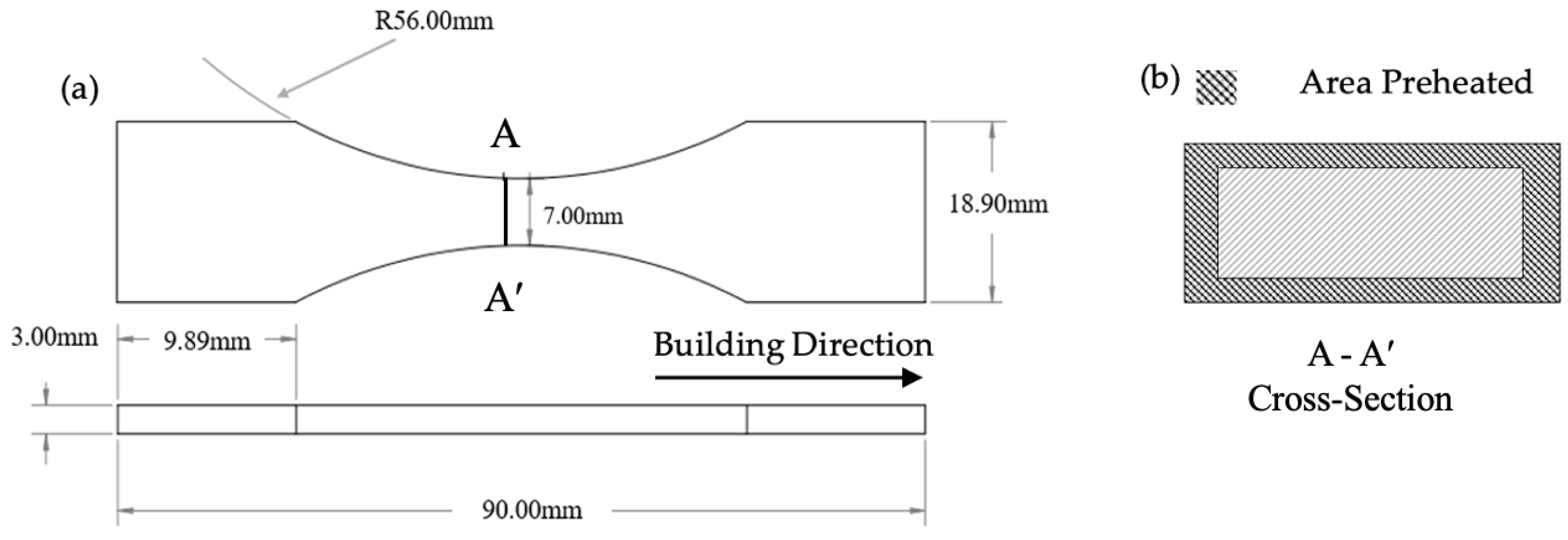
2. Materials and Methods

Gas-atomized Ti-6Al-4V powder provided by EOS North America (Pflugerville, TX, USA) was used for fabrication. The powder particles exhibit a size range of 20–80 µm and consisted of 5.50–6.75% Al, 3.50–4.50% V, 0.20% O, 0.05% N, 0.08% C, 0.015% H, 0.30% Fe and balanced Tí (wt%) meeting the requirements of ISO 5832-3 [49], ASTM F1472 [50] and ASTM F2924 [51].
SolidWorks 21 software (Dassault Systems, Vélizy-Villacoublay, France) was utilized for both the specimen designs of the microstructure (20 mm × 6 mm × 6 mm) and the continuous radius (ASTM E466) [52] test specimens (Figure 1). Both specimens were fabricated longitudinally, aligning the longer side of the specimen to be perpendicular to the z-axis of the printer (building direction).
The specimens were fabricated in an EOS M290 3D printer (EOS GmbH, Electro Optical Systems, Krailling, Germany) equipped with a 1070 nm wavelength and 400 W Ytterbium fiber laser capability. The building plate was preheated to 80 °C and maintained the preheating temperature throughout the fabrication process to minimize the thermal gradients within the initial layers of the printing.
To quantize the laser scanning parameters’ effect, the energy density of the scanning strategies was calculated using Equation (1), where Ev represents the energy density (J/mm3), P is the laser power (W), v is the laser scanning speed (mm/s), t is the layer thickness (mm), and h is the hatch spacing (mm) [53].
E v = P v · h · t
In this study, the novel approach of the multi-laser scan’s application was applied for preheating the powder particles only on the selected regions of the cross-section of the specimens with a lower laser scan power. As the samples were fabricated vertically along the tensile testing direction, the outer surface of the specimen was preheated using the respective energy densities before the melting scan was performed along the entire cross-section as shown in Figure 1b. Reference samples (non-preheated) were fabricated using only a melting laser scan with the default process parameters. The default laser parameters for melting were recommended by the manufacturer and defined as a laser power of 280 W, a scan speed of 1300 mm/s, a hatch spacing of 120 µm, and a layer thickness of 40 µm, resulting in an energy density of 44.87 J/mm3 [54]. The laser spot size was 100 µm and has a Gaussian-distributed energy. Other scanning parameters were defined as a stripe scanning strategy and a hatch angle of 47°. For the proposed layerwise local preheating application, two different laser energy density values were selected to evaluate the effect of the preheating laser scan on the microstructure of the LPBF-fabricated Ti-6Al-4V. First, a preheating energy density equivalent to 60% of the melting laser scan energy was selected to mimic the relationship between the melting temperature and the β-transus temperature of Ti-6Al-4V. (Tβ = ~950–1050 °C and Tm = ~1600–1660 °C (Tβ = ~0.6 Tm)). Then, an energy density of 80%, higher than the preheating value of 60% but lower than that in the existing literature (100%), was chosen as the median. Amounts of 60% and 80% of the melting laser scan energy density were applied to study the effect of the preheating laser scan on the sub-surface microstructure. Except for the laser power, other process parameters were kept constant between the melting laser scan and the preheating laser scan. The preheating laser scan power was selected as 168 W and 224 W for the 60% and 80% energy densities of the melting laser scan, respectively. All specimens were carefully removed from the building plate using a wire electrical discharge machining (EDM) cutter (EDM Network, Inc., Sugar Grove, IL, USA).
Microstructure evaluations of porosity and grain morphology were examined using a scanning electron microscope (SEM). A Hitachi S-3000N variable pressure (Hitachi, Santa Clara, CA, USA) was utilized for microstructure imaging studies. SEM micrographs were processed using Image J 1.53 [55] software for a robust analysis (three different regions at magnification levels of 500× and 800×). The image processing includes the conversion of micrographs to RGB stack files for the threshold adjustment of the gray-scale images with an appropriate/adequate contrast to distinguish the microstructure features. The average data reported by Image J was used to quantize the porosity and the α/α’ lath thickness [56]. To prepare samples for SEM characterization, they were first cold-mounted into a mixture of epoxy resin and hardener followed by surface grinding and polishing using an E-prep 4™ polisher (Allied High-Tech Products Inc., Rancho Dominguez, CA, USA). The grinding process was conducted using silicon carbide (SiC) abrasive disks ranging from 360 to 1200 grit sizes. For the first step of the polishing, a DiaMat polishing cloth with a 1 µm diamond suspension was employed, then, for the final polishing step, a 0.04 µm colloidal silica on a Red Final C polishing cloth pad was applied to achieve scratch-free, mirror-like sample surfaces. Samples were rinsed with micro-organic soap and cleaned using isopropyl alcohol. Surface preparation was finalized with surface etching using Kroll’s reagent (1–3 mL of HF, 2–6 mL of HNO3, 100 mL of water) to delineate grain boundaries and phases.
A SEM micrograph was used to evaluate the fine microstructural features at a high magnification level. The resolution was enhanced using the ESRGAN [57] deep learning algorithm, followed by fine-tuning for contrast and brightness using the Python 3.10.0 OpenCV library [58].
A NORAN Systems 7 Thermo Fisher Scientific (Waltham, MA, USA) detector was used for electron diffraction spectroscopy (EDS) analysis to identify the chemical composition variance in the microstructure of the Ti-6Al-4V within the spectral resolution degradation of 3% up to 60% of the dead time. For EDS analysis, a point-and-shoot analysis was conducted for the preheated and core regions, respectively, at least three times to verify if there was any variability. One of them is added later in the manuscript.
A Bruker D8 Advance X-ray diffractometer (Bruker Corporation, Madison, WI, USA) was employed for the structural analysis of the fabricated material, utilizing a Cu K-alpha wavelength of 1.5406 Å, a current of 40 mA, and a voltage of 40 kV at room temperature with 0.05° step intervals. Measurements were conducted at a speed of 1/step, with 2θ ranging from 20° to 80°. X-ray diffraction (XRD) analyses were studied to identify the phases and grain texture of each sample’s microstructure. Using Bragg’s law [59], the lattice parameters of a and c were calculated. As shown in Equations (2) and (3), inter-planar spacing d and lattice parameters were obtained in which h, k, and l indicate Miller indices:
λ = 2 d s i n ( θ )
1 d 2 = 4 3 h 2 + h k + k 2 a 2 + l 2 c 2
In order to investigate the microstrain condition of the microstructure within the reference and preheating laser scan application, the Williamson-Hall (W-H) analysis was utilized [60], which is illustrated in Equation (4). In this equation, β , D, and ε are the peak broadening, crystallite size, and microstrain, respectively. To calculate the microstrain, β c o s θ was plotted versus 4 s i n θ in which the slope gives the amount of microstrain within the microstructure. The peak broadening of related XRD peaks is considered to be the full-width-at-half-maximum (FWHM) obtained by fitting a calculated profile on the real XRD data using OriginPro 8.5 software. Si standard reflection (0.0013 rad) [61] was subtracted before strain analysis using the W-H method. Furthermore, it needs to be noted that θ can be obtained from the peak positions achieved by the multi-peak fitting analysis in which the wavelength ( λ ) and k are 1.5406 Å and 0.94, respectively.
β c o s θ = λ k D + 4 ε s i n θ
Mechanical testing for both tensile and fatigue tests were conducted using a Shimadzu EHF E-Series (100 kN) with a 4830-servo controller (Shimadzu Scientific Instruments, Inc., Missouri City, TX, USA). Test equipment are coupled with a digital image correlation (DIC) system (Correlated Solutions, Inc., Irmo, SC, USA) for precise strain measurement. The displacement and strain at the surface were monitored by tracking the light intensity patterns of high-contrast speckles on the specimen surface. Two Grasshopper GS3-U3-23S6M (FLIR Systems, Inc., Santa Barbra, CA, USA) CCD cameras with 2.3 MP each, and a pixel array of 1920 × 1200, were utilized for image capturing during testing. The correlation of the test equipment data and the image processing were performed using VIC-3D-9® software (Correlated Solutions, Inc., Irmo, SC, USA). The loading rate for tensile testing was determined to be 1.2 mm/min according to the recommended testing standard for LPBF-fabricated Ti-6Al-4V [62]. The stress-controlled fatigue test parameters were a 5.232 kN applied load under a 50 Hz frequency and an R = 0.1. In order to verify the variability in the tensile test and fatigue results, three specimens were tested in each of the preheating cases as well as reference specimens for the tensile test and fatigue results. So, a total of 18 Specimens were fabricated.
The surface roughness of the fatigue specimens was measured by a Mitutoyo Surfest SJ-210 profilometer (Mitutoyo America Co., Aurora, IL, USA). Roughness measurements were conducted following ISO 21920-2 [63] at least three times and the average value was used for the comparison and the evaluation of the applied layerwise locally preheating laser scan of LPBF-fabricated Ti-6Al-4V.

3. Results

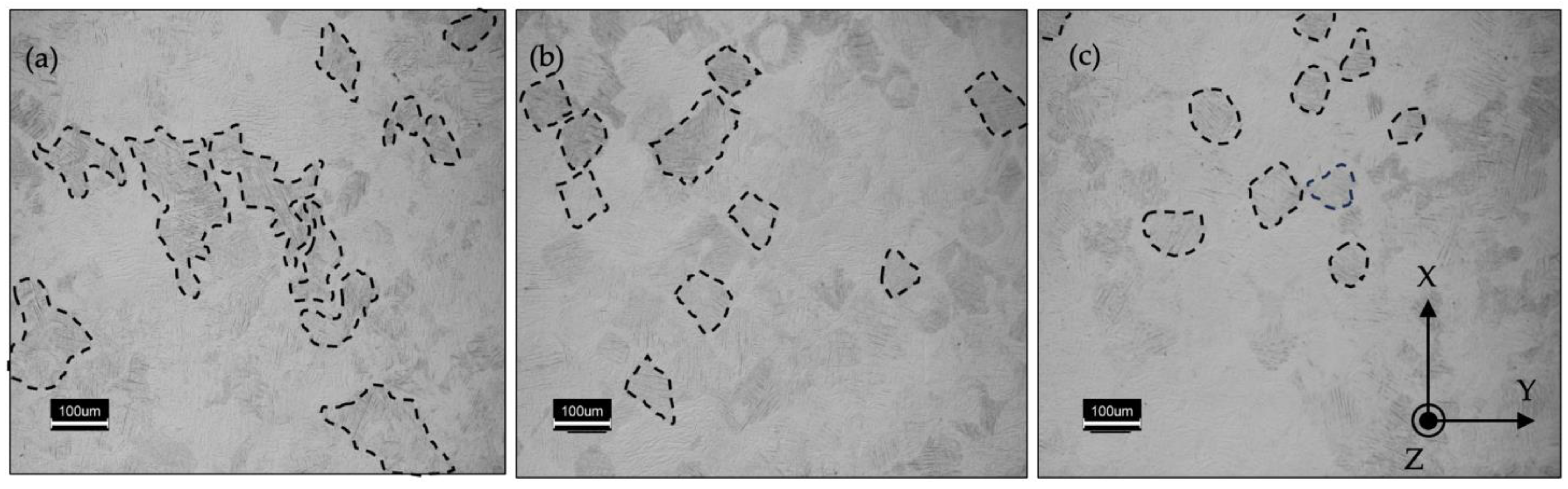
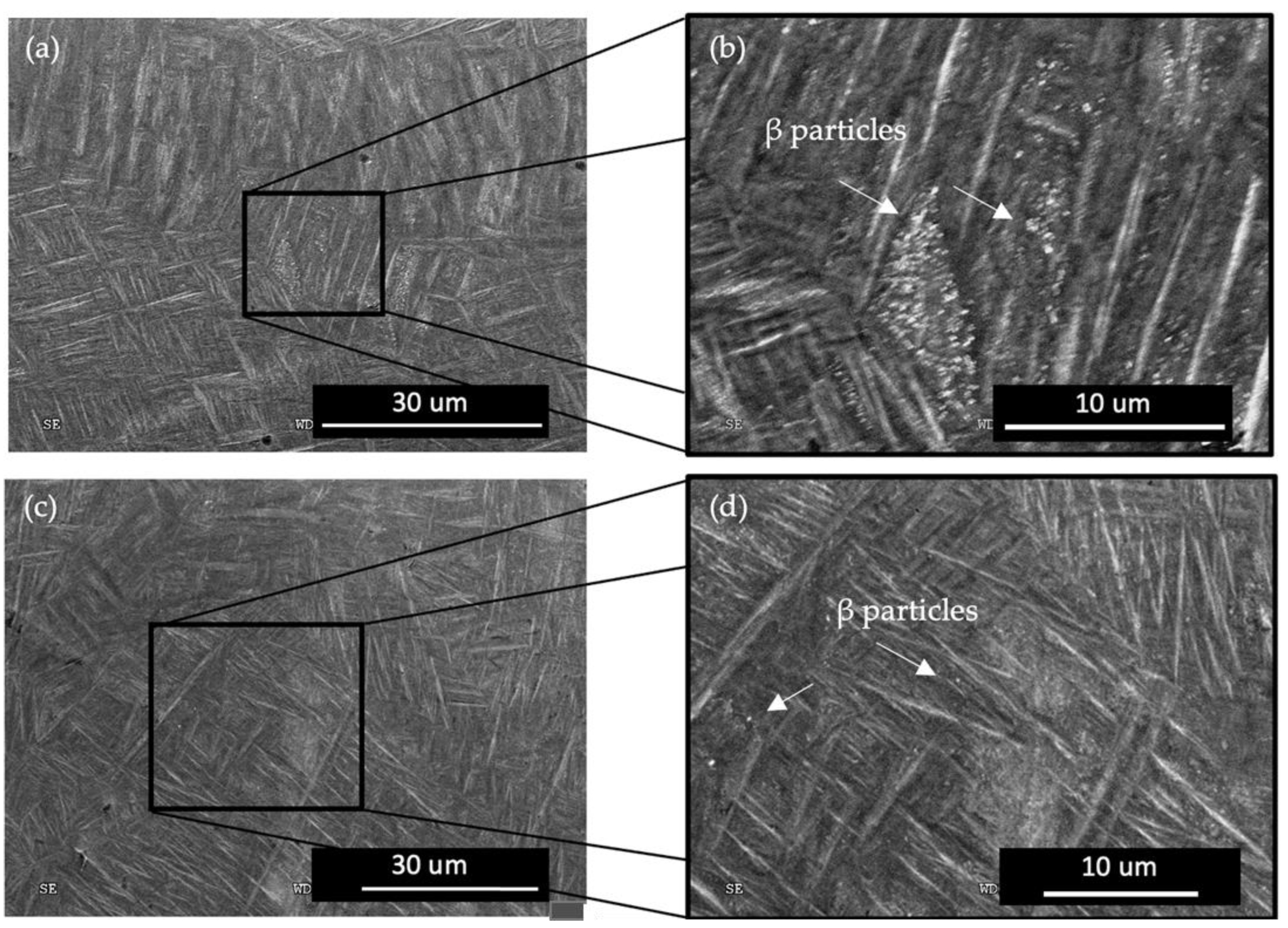
3.1. Microstructure Modification

It was observed that the reference sample without any preheating laser scan has randomly distributed polygonal shaped prior β grains along the XY plane (perpendicular to the building direction); however, prior β grains were elongated and oriented vertically along the building direction, which is consistent with previous studies [7]. Darker regions in Figure 2 depict the prior β grains.
Further investigation into prior β-grains revealed that the energy level introduced to the microstructure during the preheating laser scan has an effect on the grain morphology. Results unveiled that prior β-grain boundaries changed from being random and polygonal to being quadratic and finally to a circular shape with the increase of the energy density. Figure 3 depicts the prior β-grain boundaries of the reference, and those following preheating with 26.92 J/mm3 and 35.90 J/mm3.
Additionally, the modification of the α-phase was evaluated and it was noticed that the preheating laser scan adjusts the lath size of the LPBF-fabricated Ti-6Al-4V. Figure 4 depicts the micrographs of the reference and of the preheated regions of the specimens. Lath thickness was also quantized by image processing to gain a better understanding of the effect of the preheating energy density on the microstructure.
Figure 4 plots the average lath thickness of the reference sample as 0.797 ± 0.006 µm. Both preheating energy densities increased the lath thickness of the α/α′ phase and it was measured to be 0.933 ± 0.025 µm and 0.827 ± 0.041 µm for Ev = 26.92 J/mm3 and Ev = 35.90 J/mm3, respectively. The thickness variation of the α/α′ phase between the reference (no preheating) specimen and the core regions of the preheated sample, where there was no preheating laser scan, was insignificant.
Micrographs at higher magnification levels (≥5000×) exposed β grains at room temperature (RT) in the microstructure of the preheated region with an Ev = 35.90 J/mm3. It was observed that the β-grain regions at RT were not significant in the other specimens (Figure 5).
EDS analysis was conducted to examine the chemical composition of the bright regions. It was observed that the bright regions had higher vanadium contents, vanadium being the β-phase stabilizer element of the Ti-6Al-4V alloy. The chemical composition in Figure 6a was measured to be 5.30% ± 0.08 Al (wt.%), 3.13% ± 0.01 V (wt.%), and 91.57% ± 0.07 Ti (wt.%), and in Figure 6b, it was measured to be 5.32% ± 0.11 Al (wt.%), 3.09% ± 0.01 V (wt.%), and 91.57% ± 0.01 Ti (wt.%).
The internal defects of the microstructure were quantized during microstructure characterization by image processing. The initial microstructure of the LPBF-fabricated Ti-6Al-4V was measured to be 0.47% ± 0.015. The porosity level of the microstructure was measured to be 0.041% ± 0.011 and 0.030% ± 0.03 for the preheating laser scans of Ev = 26.92 J/mm3 and Ev = 35.90 J/mm3, respectively.

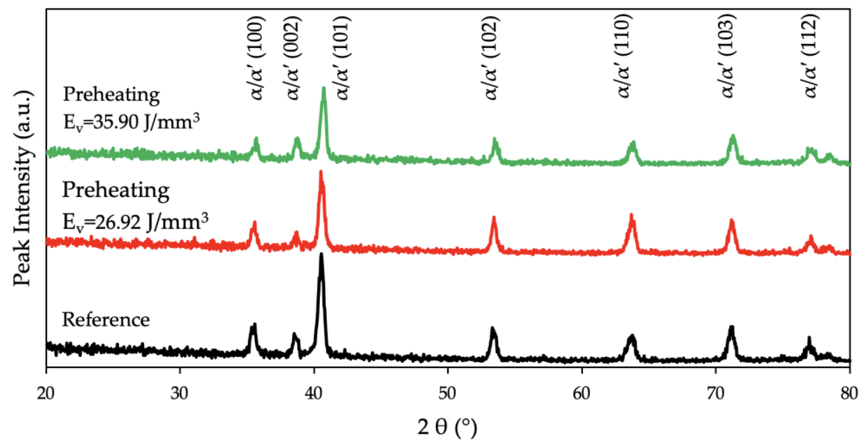
3.2. Crystallography

Regarding the crystallographic characterization of the material conducted through XRD analysis, Figure 7 depicts the diffraction patterns of the reference and of the preheated samples. The highest peak intensity was observed at (101) for the reference and the preheated samples. The reference sample had the highest intensity and the preheated sample with an Ev = 35.90 J/mm3 had the lowest intensity at (101). Additionally, a reduction at the full width half maxima (FWHM) with the application of the preheating laser was observed.
The XRD data quantized through the W-H model and the microstrain value are plotted in Figure 8. Results did not show a distinct variation between the reference sample with the initial condition and the surface-preheated regions of the specimens. It was observed that plotted graphs exhibit a positive slope which is the result of the tensile strain.
In addition to the W-H analysis, the lattice parameters were calculated according to Bragg’s law. The c/a ratios of the reference sample, the preheated sample with an Ev = 26.92 J/mm3, and with an Ev = 35.90 J/mm3 were calculated as 1.5904, 1.5954, and 1.5990, respectively. A lattice strain at the layerwise surface-preheated regions was observed in the microstructure. The lattice parameters of the α-Ti (Hexagonal Closed Pack—HCP) are plotted in Figure 8d. The results show that the preheating laser scan decreased the lattice parameters of the α-Ti.

3.3. Surface Properties

The surface roughness profile of the specimens was plotted in Figure 9. The preheated specimen with an Ev = 26.92 J/mm3 demonstrated the roughest surface among the other specimens. The finest surface finish was observed on the preheating specimen with the laser energy density of Ev = 35.90 J/mm3. The average roughness of the reference sample without the preheating laser scan was measured as Ra = 10.4 ± 0.6 µm. The finer surface that was observed in the preheated sample (Ev = 35.90 J/mm3) was Ra = 8.7 ± 0.9 µm. The other preheated specimen (Ev = 26.92 J/mm3) exhibited a roughness value of Ra = 11.6 ± 0.8 µm.

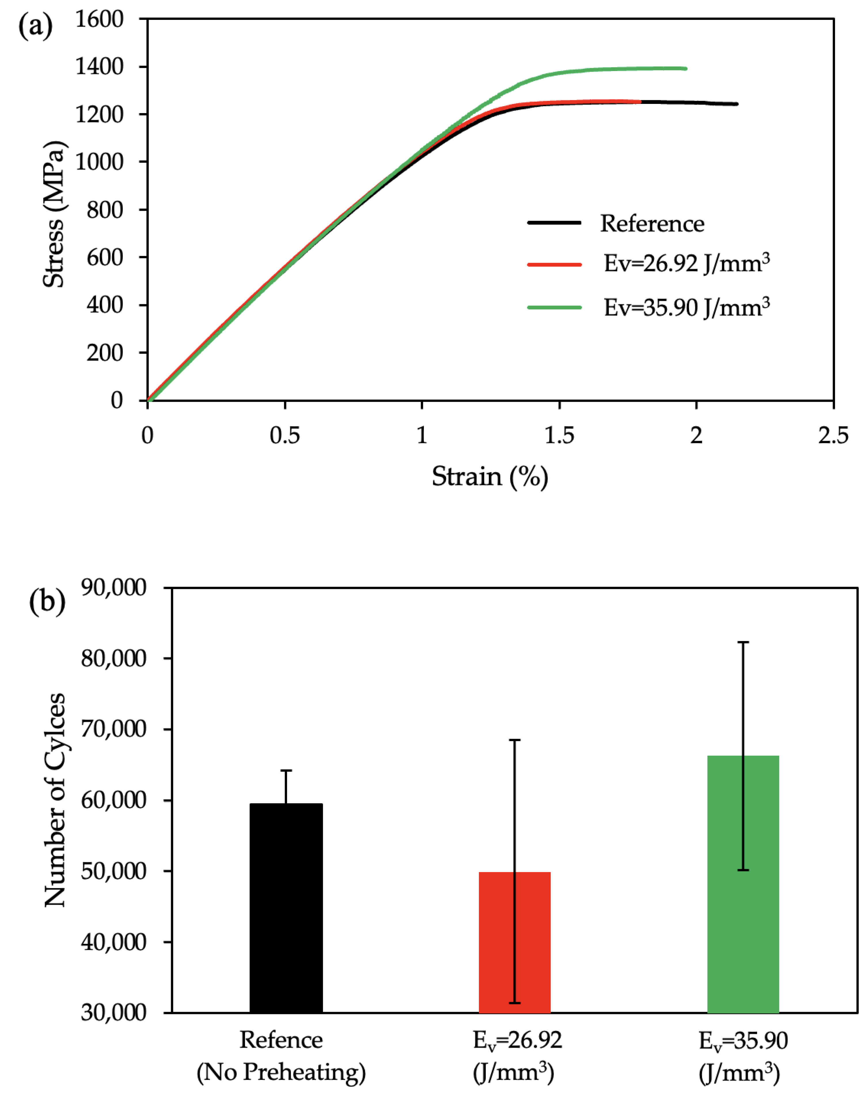
3.4. Mechanical Properties

The tensile test results are plotted in Figure 10a, where a black line represents the reference sample without any preheating laser scan, and the red and green lines represent the preheated samples with an Ev = 26.92 J/mm3 and an Ev = 35.90 J/mm3, respectively. The measured Ultimate Tensile Strength (UTS) values were 1242 Mpa, 1253 Mpa, and 1390 Mpa for the reference, the specimen preheated with an Ev = 26.92 J/mm3, and the specimen preheated with an Ev = 35.90 J/mm3, respectively. The preheated specimen with an Ev = 35.90 J/mm3 showed a significant enhancement in mechanical strength (UTS) of about 12% above the reference, whereas the specimen with an Ev = 26.92 J/mm3 had a similar strength with a lower elongation. Compared to the reference sample, both the preheated samples exhibit a lower elongation. The observed maximum strain during the tensile test for the specimens, the reference, preheated with an Ev = 26.92 J/mm3, and preheated with an Ev = 35.90 J/mm3, were 2.14%, 1.79%, and 1.96%, respectively.
Fatigue test results were also plotted in Figure 10b. It was observed that the applied layerwise surface preheating improved the total number of cycles during the fatigue test for the specimen with a preheating of an Ev = 35.90 J/mm3. However, the average fatigue life of the preheating laser scan application at an Ev = 26.92 J/mm3 exhibits a lower lifetime compared to the average of the reference specimens without any preheating application.

4. Discussion

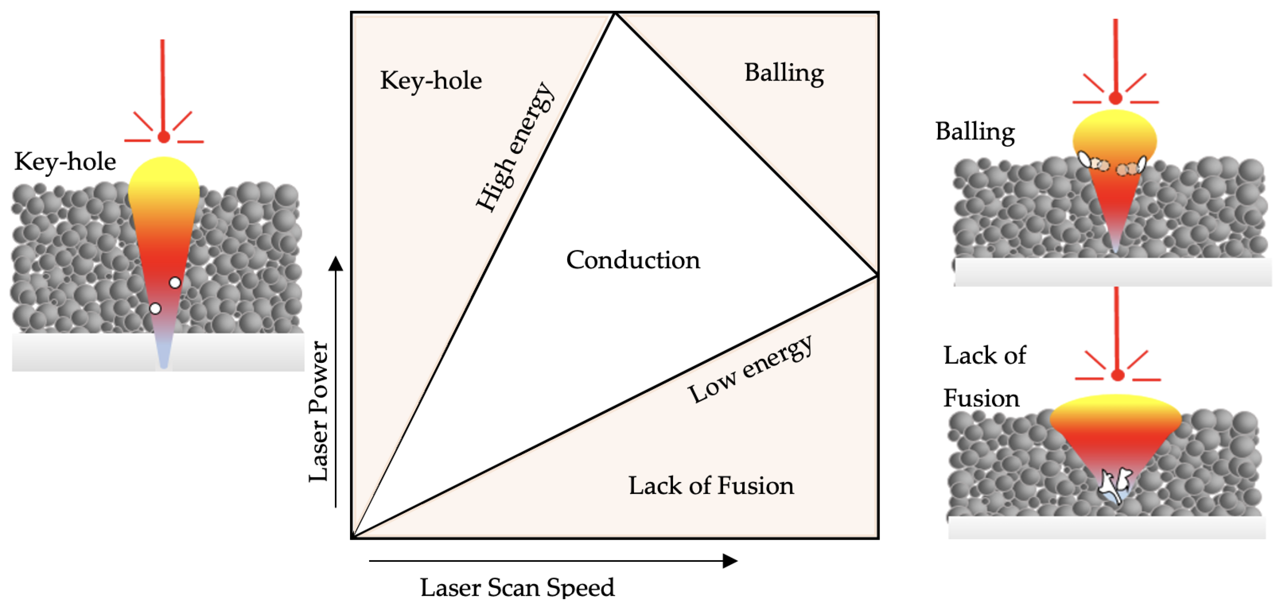
4.1. Preheating Laser Scan Energy Management to Control Defect Formation

One of the objectives of this study is to regulate the cooling and solidification rates to modify the LPBF-fabricated Ti-6Al4V material’s microstructure. A slower cooling can be achieved by using a higher energy input; however, if the high energy is delivered to the powder bed at once during the melting laser scan, the melt pool transforms from conduction to key-hole mode [64]. In key-hole mode, the excessive energy at the laser source’s center exceeds the evaporation temperature of the Ti-6Al-4V. Consequently, this excessive energy at the center of the Gaussian laser beam reshapes the melt pool hydrodynamics with a deeper melt pool and causes gas porosities [65]. Thus, the authors consider it to be a boundary condition during the process design and introduce the total energy to the powder bed in a sequence to avoid the defect formation due to key-hole mode (Figure 11).
A preheating laser scan was introduced to the powder bed selectively to increase the total energy input, decreasing the cooling and solidification rates compared to those of the single melting laser scan (the default application of the reference sample). The multi-laser scan approach has been studied previously [66,67]. However, their primary focus was developing a better understanding of the re-melting effect on the material’s microstructure and mechanical response by using equivalent laser parameters. The effect of the preheating laser scan on the full cross-section was presented and revealed that the preheating laser scan improves the mechanical strength by reducing the elongation [56].
In the present study, the authors have taken the previous research a step further by selectively applying the preheating laser scan to enhance the surface strength while minimizing the reduction in elongation which is discussed in the following sections. The relation between the β-phase transformation temperature and the melting point of the Ti-6Al-4V (Tβ ≈ 0.6 Tm) has been replicated in the selection of energy for the preheating laser scan which promotes the grain structure recrystallization and relieves the internal residual stress. For the second preheating energy level, the effect of the 100% laser scan energy for a multi-scan approach is reported. So, the authors have selected the median between 60% and 100% as the second preheating energy value for investigation in the layerwise selectively applied preheating laser scan where the literature lacks sufficient information. During the application of both preheating energy values, however, there was a partial melting between contact points of some powder grains after the fully melting preheating did not occur consistently with the laser sintering process, especially for the energy level of Ev = 35.90 J/mm3 [68].

4.2. Microstructure Refinement in Ti-6Al-4V Using LPBF

It is known that the overall morphology of the prior β-grain boundaries varies due to the directional cooling and solidification in the LPBF process [69]. The microstructure of the specimens demonstrates consistent phenomena in both the reference and the preheated regions based on the electron micrographs. The additional energy introduced to the microstructure during the preheating laser scan did not affect this aspect; however, it was observed that the preheating laser scan modifies the prior β-grain structure along the XY plane. Figure 3 reveals the response of the grains with respect to the applied preheating laser scan energy density. It was discovered that a low-energy preheating laser scan led to a quadratic grain structure where a higher preheating laser scan energy ended in a circular prior β-grain structure. This response of the prior β grain is in parallel with that of a previous study [70]. Comparing the geometry of the prior β grains, surface area degradation was observed with the introduction of the preheating laser scan. Similar grain refinement of the prior β-grain structure was studied by Zou et al. [70] where the effect of the prior β-grain structure on the tensile properties of Ti-6Al-4V was reported. Authors modified the prior β-grain structure using a post-HT and the results revealed that a finer prior β-grain structure significantly improved (≥3 times) the elongation characteristic of the LPBF-fabricated Ti-6Al-4V [70].
It is well understood that the α/αˈlaths grow along ∼45° of the prior β-grain boundaries, which is a result of the favorable Burgers orientation relationships [71,72,73]. Figure 4 depicts the α/αˈlaths mostly oriented towards ∼45° with respect to the specimens’ edges along the XY plane. It is demonstrated that the layerwise surface-preheating laser scan increased the average lath thickness significantly with the application of an Ev = 26.92 J/mm3. However, the impact of the surface preheating on the lath thickness upon the application of an Ev = 35.90 J/mm3 was not as noticeable as that of the application of an Ev = 26.92 J/mm3. The lath thickness increase with the introduction of the preheating scan can be rationalized with the reduction of the cooling rate with the higher energy input compared to the reference sample [56]. When it comes to the comparison of the α/αˈlaths between the two preheating applications, the cooling rate itself was not enough to understand the reaction of the microstructure. A more sophisticated approach was required where the β → α decomposition was deeply investigated to understand the divergence between the applied preheating energy densities. Etesami et al. [74] reported that at very high cooling rates, β transforms to α’. At relatively lower cooling rates, it decomposes to secondary α with a rod-shaped β between the α boundaries. The authors concluded that a further decrease in the cooling rate resulted in the β’s decomposition to thick secondary α lath at the boundaries. This information sheds light on the thicker lath structure at the lower energy input (Ev = 26.92 J/mm3) during the preheating laser scan. It was assumed that the thicker lath structure at the Ev = 26.92 J/mm3 preheating microstructure consists of rod-shaped β grains and that they could have been counted towards α/αˈlaths during image processing. Further evaluation of the microstructure features will be conducted in the upcoming studies.
Micrographs at higher magnifications verified the β → α decomposition disparity between the applied energy densities during the preheating laser scan of the building process in the present study. Figure 5b demonstrates the bright particles in the microstructure at RT over higher magnifications. The reference sample had very few white particles compared to the preheated sample at an Ev = 35.90 J/mm3. Some studies reported them to be a β phase at RT [56,74], whereas Liu et al. [75] concluded similar such bright particles to be Ti3Al precipitates. The oversaturated vanadium atoms were expelled from the α phase during the long-term aging process and Ti3Al started to precipitate when the content of the aluminum surpassed the critical solid solubility of the Ti3Al. Additionally, Pantawane et al. [76] reported these bright regions to be the Al-rich regions and claimed that etching using Kroll’s etchant corroded the β phase faster where the darker regions were vanadium-rich. However, their methodology could not disclose a chemical composition variation due to the limited sensitivity of their instruments [76]. Liu et al. [75] confirmed the Al precipitates via XRD patterns. With respect to such varying instances, in the present study, XRD analysis was conducted (Figure 7) and Ti3Al (α2) was not detected in the diffraction patterns, which concludes the discussions of the bright particle region being the β particles [46,77,78,79]. The results of the EDS analysis supported this assertion, as the region with the bright particles had a higher amount of vanadium which stabilizes the β-phase. In Figure 6a, the vanadium content was higher at 3.13% ± 0.01 (wt.%) compared to the region without bright particles in Figure 6b, which had a vanadium content of 3.09% ± 0.01 (wt.%).
It is evident that a higher energy input during the layerwise surface-preheating laser scan transformed the amount of β-particle precipitation and its distribution in the LPBF-fabricated Ti-6Al-4V microstructure (Figure 5). In parallel to this finding, Etesami et al. [74] reported that increasing the preheating temperature of the building plate to 200 °C during the LPBF of Ti-6Al-4V affected the β particles in the microstructure. It was reported that increasing the build plate’s temperature promotes the formation of β, compared to the relatively low preheating temperature and the as-built condition [74].
The quantized data from the XRD patterns are plotted in Figure 8. A previous study reported the effect of thermal processing on the HCP lattice structure of the LPBF-fabricated Ti-6Al-4V [56]. Due to the limited application area of the preheating laser scan in the specimen cross-section, the crystallographic modification of the material was not observed at the same level as the fully preheated microstructure [56,80]. Additionally, no trend was disclosed in the microstrain value between the different preheating energy densities. All the specimens exhibit a positive slope which indicates the presence of the tensile strain [81]. However, the lattice parameters, both a and c, were decreased in both preheating laser scan applications. It is evident that the c/a ratio increased with the applied preheating laser scan. To the authors’ knowledge, this increment is related to the lattice strain’s relaxation [82]. Previous studies investigated the lattice’s deformation and reported the mechanical response of the material [83,84]. The effects on the microstructure can be correlated to the mechanical properties as follows.

4.3. Functionally Graded Microstructure for the Enhanced Fatigue Behavior of LPBF-Fabricated Ti-6Al-4V

This study explores a novel approach to enhancing the fatigue strength of LPBF-fabricated Ti-6Al-4V by functionalizing the microstructure through controlled cooling rates at selected regions, a method not previously investigated. Published studies aiming to create a functionalized microstructure for specific mechanical properties modified the microstructure of the Ti-6Al-4V using additional elements or compounds [85,86,87]. Due to the discrepancy between the melting characteristics of the main material (Ti-6Al-4V) and those of the additive elements and compounds, these applications are challenging in terms of their process-induced defects. The energy input during the fabrication requires precise control and adjustment. Moreover, the homogenous particle distribution of the additional elements and compounds during powder spreading is difficult to standardize and an inhomogeneous element distribution was reported [86]. The proposed methodology (Figure 12) modified the microstructure and surface characteristics due to the applied region of the specimens while keeping the chemical homogeneity. Furthermore, the process defects reported in the previous studies that require some effort to overcome were not a concern in the presented study [87].
The enhancement in the mechanical strength of the Ev = 35.90 J/mm3 specimen when compared with that of the Ev = 26.92 J/mm3 specimen could be attributed to both the prior β-grain refinement and the improved surface finish values. The effect of the finer prior β grain is discussed in detail in the previous section. The rougher the specimen, the lower its strength. Greitemeier et al. [88] observed that the EBM specimen gave rise to Ti-6Al-4V samples with rougher surfaces in comparison with the laser-powder-bed-fusioned Ti-6Al-4V samples, which correlated negatively with its tensile strength. An investigation made by Liu et al. [89] over the α lath thickness vs. deformation ability proved that a higher lath thickness induces easier deformation due to an increased density of dislocations. From Figure 4d it can be proven that the lath thickness increase in the Ev = 26.92 J/mm3 sample had a lower strength compared to that of the Ev = 35.90 J/mm3 sample.
Figure 9 shows that the preheating laser scan with the energy level of Ev = 35.90 J/mm3 improved the surface finish of the LPBF-fabricated Ti-6Al-4V significantly. The average roughness of the reference sample was improved by 16% with the application of layerwise surface preheating (Ev = 35.90 J/mm3). This finer surface is a result of the partial melting during the preheating laser scan. Applied energy caused partial melting and agglomerated some particles which impeded the scattering of the powder particles during the melting laser scan. Khorasani et al. [90] reported that a higher total energy input caused a wider melt pool during the melting scan which overflowed to the outer powder particles and led to a reduction in the surface quality. However, the total energy was higher in the preheating laser scan (Ev = 35.90 J/mm3) since the energy was not applied at once, and the results proved the surface quality was improved. On the contrary, the preheating laser with the energy density of Ev = 26.92 J/mm3 weakens the surface finish, which can be justified by the effect of the preheating energy level on the melt pool during the melting scan, and a future study will address this and seek to find the optimum surface preheating laser scan strategy.
The primary aim of this study is to present the proof of the concept of modifying the microstructure of the selected regions in Ti-6Al-4V materials during LPBF fabrication without using alloying elements. Future studies could benefit from additional characterization techniques such as transmission electron microscopy (TEM) and additional mechanical testing. In the present study, it is rational to rely on the EDS analysis for the β phase (bright particles) at RT according to the vanadium content of the region because the variant is higher than the tolerance of the EDS technique (±0.01%). Also, additional information could be generated on the β → α + β decomposition by using TEM on the application of a preheating laser scan in LPFB-fabricated Ti-6Al-4V. While the results of the mechanical testing clearly indicate the effect of the applied thermal process during fabrication, future studies such as micro-hardness and four-point bending test evaluations would add more strength to this. Additionally, the authors assumed there to be a partial melting during the applied preheating, especially at the energy level of Ev = 35.90 J/m3 (80% of the melting laser scan power), in the context of the existing literature. There might be a benefit to the literature if this amount is quantized with an in situ thermal process monitoring system.

5. Conclusions

  • Microstructural analysis demonstrates that the prior β-grain boundaries differ during the LPBF process. By performing preheating, the prior β-grain structure is modified along the XY plane. Low-energy preheating results in a quadratic grain structure and high-energy preheating, on the other hand, produces a circular prior β-grain structure.
  • The α / α lath thickness is increased by performing preheating during LPBF. This increment is related to the reduction in the cooling rate resulting from the higher energy input in the preheated samples compared to the reference ones.
  • By performing preheating, the β α decomposition disparity is promoted, and some brighter regions are formed within the microstructure. Furthermore, the number of these brighter regions is enhanced by increasing the energy density in the preheated specimens. Further studies regarding these particles showed that they represent the β phase in the microstructure at RT.
  • Results of the W-H analysis assert that the microstrain does not follow any trend between the different preheating regimes; however, its value reveals the presence of the tensile strain within the microstructure. Also, it is worthwhile to note that the lattice parameters of a and c are reduced by performing preheating. Quite contrary to this, the ratio of c/a is enhanced as expected due to the lattice strain relaxation.

Author Contributions

A.A.T.: Conceptualization, writing—original draft, characterization, methodology. B.F.: formal analysis, fabrication, post-processing. A.G.-R.: writing—review and editing, testing, investigation. H.H.: investigation, data analysis. S.H.D.: writing—review and editing, theoretical investigation. A.A.: resources, supervision, conceptualization, writing—review and editing. All authors have read and agreed to the published version of the manuscript.

Funding

This research received no external funding.

Institutional Review Board Statement

Not applicable.

Informed Consent Statement

Not applicable.

Data Availability Statement

Data are contained within the article.

Acknowledgments

The authors are thankful for the characterization equipment provided by the University of Texas at the Arlington Characterization Center for Materials and Biology. Additionally, the authors would like to express their sincere gratitude to Eren Toker for his invaluable contribution to improving an image’s resolution and quality in this research.

Conflicts of Interest

Author Ahmet Alptug Tanrikulu was employed by the company Turkish Aerospace Industries. Behzad Farhang was employed by the company ArcelorMittal North America. The remaining authors declare that the research was conducted in the absence of any commercial or financial relationships that could be construed as a potential conflict of interest.

References

  1. He, Y.; Montgomery, C.; Beuth, J.; Webler, B. Melt Pool Geometry and Microstructure of Ti6Al4V with B Additions Processed by Selective Laser Melting Additive Manufacturing. Mater. Des. 2019, 183, 108126. [Google Scholar] [CrossRef]
  2. Salmi, M. Design and Applications of Additive Manufacturing and 3D Printing. Designs 2022, 6, 6. [Google Scholar] [CrossRef]
  3. Gong, H.; Rafi, K.; Gu, H.; Janaki Ram, G.D.; Starr, T.; Stucker, B. Influence of Defects on Mechanical Properties of Ti-6Al-4V Components Produced by Selective Laser Melting and Electron Beam Melting. Mater. Des. 2015, 86, 545–554. [Google Scholar] [CrossRef]
  4. Leuders, S.; Thöne, M.; Riemer, A.; Niendorf, T.; Tröster, T.; Richard, H.A.; Maier, H.J. On the Mechanical Behaviour of Titanium Alloy TiAl6V4 Manufactured by Selective Laser Melting: Fatigue Resistance and Crack Growth Performance. Int. J. Fatigue 2013, 48, 300–307. [Google Scholar] [CrossRef]
  5. Agius, D.; Kourousis, K.I.; Wallbrink, C. A Review of the As-Built SLM Ti-6Al-4V Mechanical Properties towards Achieving Fatigue Resistant Designs. Metals 2018, 8, 75. [Google Scholar] [CrossRef]
  6. Prashanth, K.G. Selective Laser Melting: Materials and Applications. J. Manuf. Mater. Process. 2020, 4, 13. [Google Scholar] [CrossRef]
  7. Liu, S.; Shin, Y.C. Additive Manufacturing of Ti6Al4V Alloy: A Review. Mater. Des. 2019, 164, 107552. [Google Scholar] [CrossRef]
  8. Gerd Lütjering, J.C.W. Titanium; Engineering Materials, Processes; Springer: Berlin/Heidelberg, Germany, 2007; ISBN 978-3-540-71397-5. [Google Scholar]
  9. Boyer, R.R. An Overview on the Use of Titanium in the Aerospace Industry. Mater. Sci. Eng. A 1996, 213, 103–114. [Google Scholar] [CrossRef]
  10. Singh, P.; Pungotra, H.; Kalsi, N.S. On the Characteristics of Titanium Alloys for the Aircraft Applications. Mater. Today Proc. 2017, 4, 8971–8982. [Google Scholar] [CrossRef]
  11. Liu, J.; Sun, Q.; Zhou, C.; Wang, X.; Li, H.; Guo, K.; Sun, J. Achieving Ti6Al4V Alloys with Both High Strength and Ductility via Selective Laser Melting. Mater. Sci. Eng. A 2019, 766, 138319. [Google Scholar] [CrossRef]
  12. Xu, Y.; Zhang, D.; Guo, Y.; Hu, S.; Wu, X.; Jiang, Y. Microstructural Tailoring of As-Selective Laser Melted Ti6Al4V Alloy for High Mechanical Properties. J. Alloys Compd. 2020, 816, 152536. [Google Scholar] [CrossRef]
  13. Yan, X.; Yin, S.; Chen, C.; Huang, C.; Bolot, R.; Lupoi, R.; Kuang, M.; Ma, W.; Coddet, C.; Liao, H.; et al. Effect of Heat Treatment on the Phase Transformation and Mechanical Properties of Ti6Al4V Fabricated by Selective Laser Melting. J. Alloys Compd. 2018, 764, 1056–1071. [Google Scholar] [CrossRef]
  14. Dai, N.; Zhang, L.C.; Zhang, J.; Zhang, X.; Ni, Q.; Chen, Y.; Wu, M.; Yang, C. Distinction in Corrosion Resistance of Selective Laser Melted Ti-6Al-4V Alloy on Different Planes. Corros. Sci. 2016, 111, 703–710. [Google Scholar] [CrossRef]
  15. Kanganga, M.; du Plessis, A.; Muvunzi, R.; Khodja, M. A Review of the Effects of Laser Shock Peening on Properties of Additively Manufactured Ti6Al4V. In Fatigue in Additive Manufactured Metals; Elsevier: Amsterdam, The Netherlands, 2024; pp. 235–257. [Google Scholar]
  16. Cao, F.; Zhang, T.; Ryder, M.A.; Lados, D.A. A Review of the Fatigue Properties of Additively Manufactured Ti-6Al-4V. Jom 2018, 70, 349–357. [Google Scholar] [CrossRef]
  17. Xu, W.; Sun, S.; Elambasseril, J.; Liu, Q.; Brandt, M.; Qian, M. Ti-6Al-4V Additively Manufactured by Selective Laser Melting with Superior Mechanical Properties. JOM 2015, 67, 668–673. [Google Scholar] [CrossRef]
  18. Sun, C.; Chi, W.; Wang, W.; Duan, Y. Characteristic and Mechanism of Crack Initiation and Early Growth of an Additively Manufactured Ti-6Al-4V in Very High Cycle Fatigue Regime. Int. J. Mech. Sci. 2021, 205, 106591. [Google Scholar] [CrossRef]
  19. Du, L.; Pan, X.; Qian, G.; Zheng, L.; Hong, Y. Crack Initiation Mechanisms under Two Stress Ratios up to Very-High-Cycle Fatigue Regime for a Selective Laser Melted Ti-6Al-4V. Int. J. Fatigue 2021, 149, 106294. [Google Scholar] [CrossRef]
  20. Walker, K.F.; Liu, Q.; Brandt, M. Evaluation of Fatigue Crack Propagation Behaviour in Ti-6Al-4V Manufactured by Selective Laser Melting. Int. J. Fatigue 2017, 104, 302–308. [Google Scholar] [CrossRef]
  21. Syed, A.K.; Ahmad, B.; Guo, H.; Machry, T.; Eatock, D.; Meyer, J.; Fitzpatrick, M.E.; Zhang, X. An Experimental Study of Residual Stress and Direction-Dependence of Fatigue Crack Growth Behaviour in as-Built and Stress-Relieved Selective-Laser-Melted Ti6Al4V. Mater. Sci. Eng. A 2019, 755, 246–257. [Google Scholar] [CrossRef]
  22. Jesus, J.S.; Borrego, L.P.; Ferreira, J.A.M.; Costa, J.D.; Capela, C. Fatigue Crack Growth Behaviour in Ti6Al4V Alloy Specimens Produced by Selective Laser Melting. Int. J. Fract. 2020, 223, 123–133. [Google Scholar] [CrossRef]
  23. Boschetto, A.; Bottini, L.; Macera, L.; Veniali, F. Post-Processing of Complex SLM Parts by Barrel Finishing. Appl. Sci. 2020, 10, 1382. [Google Scholar] [CrossRef]
  24. Liu, R.; Wang, Z.; Sparks, T.; Liou, F.; Newkirk, J. Aerospace Applications of Laser Additive Manufacturing; Elsevier Ltd.: Amsterdam, The Netherlands, 2017; ISBN 9780081004340. [Google Scholar]
  25. Kadirgama, K.; Harun, W.S.W.; Tarlochan, F.; Samykano, M.; Ramasamy, D.; Azir, M.Z.; Mehboob, H. Statistical and Optimize of Lattice Structures with Selective Laser Melting (SLM) of Ti6AL4V Material. Int. J. Adv. Manuf. Technol. 2018, 97, 495–510. [Google Scholar] [CrossRef]
  26. Seabra, M.; Azevedo, J.; Araújo, A.; Reis, L.; Pinto, E.; Alves, N.; Santos, R.; Pedro Mortágua, J. Selective Laser Melting (SLM) and Topology Optimization for Lighter Aerospace Componentes. Procedia Struct. Integr. 2016, 1, 289–296. [Google Scholar] [CrossRef]
  27. Elambasseril, J.; Rogers, J.; Wallbrink, C.; Munk, D.; Leary, M.; Qian, M. Laser Powder Bed Fusion Additive Manufacturing (LPBF-AM): The Influence of Design Features and LPBF Variables on Surface Topography and Effect on Fatigue Properties. Crit. Rev. Solid State Mater. Sci. 2022, 48, 132–168. [Google Scholar] [CrossRef]
  28. Kahlin, M.; Ansell, H.; Basu, D.; Kerwin, A.; Newton, L.; Smith, B.; Moverare, J.J. Improved Fatigue Strength of Additively Manufactured Ti6Al4V by Surface Post Processing. Int. J. Fatigue 2020, 134, 105497. [Google Scholar] [CrossRef]
  29. Vayssette, B.; Saintier, N.; Brugger, C.; Elmay, M.; Pessard, E. Surface Roughness of Ti-6Al-4V Parts Obtained by SLM and EBM: Effect on the High Cycle Fatigue Life. Procedia Eng. 2018, 213, 89–97. [Google Scholar] [CrossRef]
  30. Ge, J.; Huang, J.; Lei, Y.; O’Reilly, P.; Ahmed, M.; Zhang, C.; Yan, X.; Yin, S. Microstructural Features and Compressive Properties of SLM Ti6Al4V Lattice Structures. Surf. Coat. Technol. 2020, 403, 126419. [Google Scholar] [CrossRef]
  31. Alghamdi, A.; Downing, D.; McMillan, M.; Brandt, M.; Qian, M.; Leary, M. Experimental and Numerical Assessment of Surface Roughness for Ti6Al4V Lattice Elements in Selective Laser Melting. Int. J. Adv. Manuf. Technol. 2019, 105, 1275–1293. [Google Scholar] [CrossRef]
  32. Aufa, A.N.; Hassan, M.Z.; Ismail, Z.; Harun, N.; Ren, J.; Sadali, M.F. Surface Enhancement of Ti–6Al–4V Fabricated by Selective Laser Melting on Bone-like Apatite Formation. J. Mater. Res. Technol. 2022, 19, 4018–4030. [Google Scholar] [CrossRef]
  33. Salem, H.; Carter, L.N.; Attallah, M.M.; Salem, H.G. Influence of Processing Parameters on Internal Porosity and Types of Defects Formed in Ti6Al4V Lattice Structure Fabricated by Selective Laser Melting. Mater. Sci. Eng. A 2019, 767, 138387. [Google Scholar] [CrossRef]
  34. Chastand, V.; Tezenas, A.; Cadoret, Y.; Quaegebeur, P.; Maia, W.; Charkaluk, E. Fatigue Characterization of Titanium Ti-6Al-4V Samples Produced by Additive Manufacturing. Procedia Struct. Integr. 2016, 2, 3168–3176. [Google Scholar] [CrossRef]
  35. Hartunian, P.; Eshraghi, M. Effect of Build Orientation on the Microstructure and Mechanical Properties of Selective Laser-Melted Ti-6Al-4V Alloy. J. Manuf. Mater. Process. 2018, 2, 69. [Google Scholar] [CrossRef]
  36. Agius, D.; Kourousis, K.I.; Wallbrink, C.; Song, T. Cyclic Plasticity and Microstructure of As-Built SLM Ti-6Al-4V: The Effect of Build Orientation. Mater. Sci. Eng. A 2017, 701, 85–100. [Google Scholar] [CrossRef]
  37. Krakhmalev, P.; Fredriksson, G.; Yadroitsava, I.; Kazantseva, N.; Du Plessis, A.; Yadroitsev, I. Deformation Behavior and Microstructure of Ti6Al4V Manufactured by SLM. Phys. Procedia 2016, 83, 778–788. [Google Scholar] [CrossRef]
  38. Cai, W.; Song, Q.; Ji, H.; Gupta, M.K. Multi-Perspective Analysis of Building Orientation Effects on Microstructure, Mechanical and Surface Properties of Slm Ti6al4v with Specific Geometry. Materials 2021, 14, 4392. [Google Scholar] [CrossRef] [PubMed]
  39. Kumar, P.; Ramamurty, U. Microstructural Optimization through Heat Treatment for Enhancing the Fracture Toughness and Fatigue Crack Growth Resistance of Selective Laser Melted Ti–6Al–4V Alloy. Acta Mater. 2019, 169, 45–59. [Google Scholar] [CrossRef]
  40. Liu, Y.; Zhang, J.; Li, S.-J.; Hou, W.-T.; Wang, H.; Xu, Q.-S.; Hao, Y.-L.; Yang, R. Effect of HIP Treatment on Fatigue Crack Growth Behavior of Ti–6Al–4V Alloy Fabricated by Electron Beam Melting. Acta Metall. Sin. (Engl. Lett.) 2017, 30, 1163–1168. [Google Scholar] [CrossRef]
  41. Chastand, V.; Quaegebeur, P.; Maia, W.; Charkaluk, E. Comparative Study of Fatigue Properties of Ti-6Al-4V Specimens Built by Electron Beam Melting (EBM) and Selective Laser Melting (SLM). Mater. Charact. 2018, 143, 76–81. [Google Scholar] [CrossRef]
  42. De Biasi, R.; Murchio, S.; Sbettega, E.; Carmignato, S.; Luchin, V.; Benedetti, M. Efficient Optimization Framework for L-PBF Fatigue Enhanced Ti6Al4V Lattice Component. Mater. Des. 2023, 230, 111975. [Google Scholar] [CrossRef]
  43. Bartolomeu, F.; Gasik, M.; Silva, F.S.; Miranda, G. Mechanical Properties of Ti6Al4V Fabricated by Laser Powder Bed Fusion: A Review Focused on the Processing and Microstructural Parameters Influence on the Final Properties. Metals 2022, 12, 986. [Google Scholar] [CrossRef]
  44. Hosseini, S.M.; Vaghefi, E.; Mirkoohi, E. The Role of Defect Structure and Residual Stress on Fatigue Failure Mechanisms of Ti-6Al-4V Manufactured via Laser Powder Bed Fusion: Effect of Process Parameters and Geometrical Factors. J. Manuf. Process. 2023, 102, 549–563. [Google Scholar] [CrossRef]
  45. Xu, W.; Lui, E.W.; Pateras, A.; Qian, M.; Brandt, M. In Situ Tailoring Microstructure in Additively Manufactured Ti-6Al-4V for Superior Mechanical Performance. Acta Mater. 2017, 125, 390–400. [Google Scholar] [CrossRef]
  46. Ali, H.; Ma, L.; Ghadbeigi, H.; Mumtaz, K. In-Situ Residual Stress Reduction, Martensitic Decomposition and Mechanical Properties Enhancement through High Temperature Powder Bed Pre-Heating of Selective Laser Melted Ti6Al4V. Mater. Sci. Eng. A 2017, 695, 211–220. [Google Scholar] [CrossRef]
  47. Gomez-Gallegos, A.; Mandal, P.; Gonzalez, D.; Zuelli, N.; Blackwell, P. Studies on Titanium Alloys for Aerospace Application. Defect Diffus. Forum 2018, 385, 419–423. [Google Scholar] [CrossRef]
  48. Niinomi, M. Mechanical Biocompatibilities of Titanium Alloys for Biomedical Applications. J. Mech. Behav. Biomed. Mater. 2008, 1, 30–42. [Google Scholar] [CrossRef] [PubMed]
  49. ISO 5832-3; Implants for Surgery—Metallic Materials—Part 3: Wrought Titanium 6-Aluminium 4-Vanadium Alloy. The International Organization for Standardization: Geneva, Switzerland, 2021.
  50. ASTM F1472; Standard Specification for Wrought Titanium-6Aluminum-4Vanadium Alloy for Surgical Implant Applications. American Society for Testing and Materials: West Conshohocken, PA, USA, 2020. [CrossRef]
  51. ASTM F2924; Standard Specification for Additive Manufacturing Titanium-6 Aluminum-4 Vanadium with Powder Bed Fusion. American Society for Testing and Materials: West Conshohocken, PA, USA, 2021. [CrossRef]
  52. ASTM E466; Standard Practice for Conducting Force Controlled Constant Amplitude Axial Fatigue Tests of Metallic Materials. American Society for Testing and Materials: West Conshohocken, PA, USA, 2021. [CrossRef]
  53. Thijs, L.; Verhaeghe, F.; Craeghs, T.; Van Humbeeck, J.; Kruth, J.-P. A Study of the Microstructural Evolution during Selective Laser Melting of Ti–6Al–4V. Acta Mater. 2010, 58, 3303–3312. [Google Scholar] [CrossRef]
  54. Farhang, B.; Tanrikulu, A.A.; Ganesh-Ram, A.; Durlov, S.H.; Shayesteh Moghaddam, N. Innovative Fabrication Design for In Situ Martensite Decomposition and Enhanced Mechanical Properties in Laser Powder Bed Fused Ti6Al4V Alloy. J. Manuf. Mater. Process. 2023, 7, 226. [Google Scholar] [CrossRef]
  55. Schneider, C.A.; Rasband, W.S.; Eliceiri, K.W. NIH Image to ImageJ: 25 Years of Image Analysis. Nat. Methods 2012, 9, 671–675. [Google Scholar] [CrossRef] [PubMed]
  56. Tanrikulu, A.A.; Ganesh-Ram, A.; Farhang, B.; Amerinatanzi, A. Unveiling the Impact of Layerwise Laser Preheating on Microstructure and Mechanical Response in Laser Powder Bed Fusion. J. Mater. Sci. 2023, 58, 17362–17382. [Google Scholar] [CrossRef]
  57. Wang, X.; Yu, K.; Wu, S.; Gu, J.; Liu, Y.; Dong, C.; Qiao, Y.; Loy, C.C. ESRGAN: Enhanced Super-Resolution Generative Adversarial Networks. In ECCV 2018: Computer Vision—ECCV 2018 Workshops; Springer: Cham, Switzerland, 2019; pp. 63–79. [Google Scholar]
  58. Bradski, G. OpenCV Open Source Computer Vision Library 2015. Available online: https://github.com/opencv/opencv/wiki/CiteOpenCV (accessed on 15 January 2008).
  59. Callister, W.D., Jr. Materials Science and Engineering: An Introduction, 7th ed.; John Wiley & Sons: New York, NY, USA, 2007. [Google Scholar]
  60. Khorsand Zak, A.; Majid, W.H.A.; Abrishami, M.E.; Yousefi, R. X-ray Analysis of ZnO Nanoparticles by Williamson-Hall and Size-Strain Plot Methods. Solid State Sci. 2011, 13, 251–256. [Google Scholar] [CrossRef]
  61. Bagasol, A.J.I.; Kaschel, F.R.; Ramachandran, S.; Mirihanage, W.; Browne, D.J.; Dowling, D.P. The Influence of a Large Build Area on the Microstructure and Mechanical Properties of PBF-LB Ti-6Al-4 V Alloy. Int. J. Adv. Manuf. Technol. 2023, 125, 1355–1369. [Google Scholar] [CrossRef] [PubMed]
  62. Pasang, T.; Tavlovich, B.; Yannay, O.; Jakson, B.; Fry, M.; Tao, Y.; Turangi, C.; Wang, J.C.; Jiang, C.P.; Sato, Y.; et al. Directionally-Dependent Mechanical Properties of Ti6Al4V Manufactured by Electron Beam Melting (EBM) and Selective Laser Melting (SLM). Materials 2021, 14, 3603. [Google Scholar] [CrossRef] [PubMed]
  63. ISO 21920-2; Geometrical Product Specifications (GPS) Surface Texture: Profile Part 2: Terms, Definitions and Surface Texture Parameters. International Standardization Organization: Geneva, Switzerland, 2021.
  64. Tenbrock, C.; Fischer, F.G.; Wissenbach, K.; Schleifenbaum, J.H.; Wagenblast, P.; Meiners, W.; Wagner, J. Influence of Keyhole and Conduction Mode Melting for Top-Hat Shaped Beam Profiles in Laser Powder Bed Fusion. J. Mater. Process. Technol. 2020, 278, 116514. [Google Scholar] [CrossRef]
  65. Pal, S.; Gubeljak, N.; Hudák, R.; Lojen, G.; Rajťúková, V.; Brajlih, T.; Drstvenšek, I. Evolution of the Metallurgical Properties of Ti-6Al-4V, Produced with Different Laser Processing Parameters, at Constant Energy Density in Selective Laser Melting. Results Phys. 2020, 17, 103186. [Google Scholar] [CrossRef]
  66. Bedmar, J.; de la Pezuela, J.; Riquelme, A.; Torres, B.; Rams, J. Impact of Remelting in the Microstructure and Corrosion Properties of the Ti6Al4V Fabricated by Selective Laser Melting. Coatings 2022, 12, 284. [Google Scholar] [CrossRef]
  67. Karimi, J.; Suryanarayana, C.; Okulov, I.; Prashanth, K.G. Selective Laser Melting of Ti6Al4V: Effect of Laser Re-Melting. Mater. Sci. Eng. A 2021, 805, 140558. [Google Scholar] [CrossRef]
  68. Ramosena, L.A.; Dzogbewu, T.C.; du Preez, W. Direct Metal Laser Sintering of the Ti6Al4V Alloy from a Powder Blend. Materials 2022, 15, 8193. [Google Scholar] [CrossRef] [PubMed]
  69. Wu, S.Q.; Lu, Y.J.; Gan, Y.L.; Huang, T.T.; Zhao, C.Q.; Lin, J.J.; Guo, S.; Lin, J.X. Microstructural Evolution and Microhardness of a Selective-Laser-Melted Ti–6Al–4V Alloy after Post Heat Treatments. J. Alloys Compd. 2016, 672, 643–652. [Google Scholar] [CrossRef]
  70. Zou, Z.; Simonelli, M.; Katrib, J.; Dimitrakis, G.; Hague, R. Microstructure and Tensile Properties of Additive Manufactured Ti-6Al-4V with Refined Prior-β Grain Structure Obtained by Rapid Heat Treatment. Mater. Sci. Eng. A 2021, 814, 141271. [Google Scholar] [CrossRef]
  71. Kumar, P.; Prakash, O.; Ramamurty, U. Micro-and Meso-Structures and Their Influence on Mechanical Properties of Selectively Laser Melted Ti-6Al-4V. Acta Mater. 2018, 154, 246–260. [Google Scholar] [CrossRef]
  72. Lee, E.; Banerjee, R.; Kar, S.; Bhattacharyya, D.; Fraser, H.L. Selection of α Variants during Microstructural Evolution in α/β Titanium Alloys. Philos. Mag. 2007, 87, 3615–3627. [Google Scholar] [CrossRef]
  73. Antonysamy, A.A.; Meyer, J.; Prangnell, P.B. Effect of Build Geometry on the β-Grain Structure and Texture in Additive Manufacture of Ti6Al4V by Selective Electron Beam Melting. Mater. Charact. 2013, 84, 153–168. [Google Scholar] [CrossRef]
  74. Etesami, S.A.; Fotovvati, B.; Asadi, E. Heat Treatment of Ti-6Al-4V Alloy Manufactured by Laser-Based Powder-Bed Fusion: Process, Microstructures, and Mechanical Properties Correlations. J. Alloys Compd. 2022, 895, 162618. [Google Scholar] [CrossRef]
  75. Liu, Y.; Xu, H.; Zhu, L.; Wang, X.; Han, Q.; Li, S.; Wang, Y.; Setchi, R.; Wang, D. Investigation into the Microstructure and Dynamic Compressive Properties of Selective Laser Melted Ti–6Al–4V Alloy with Different Heating Treatments. Mater. Sci. Eng. A 2021, 805, 140561. [Google Scholar] [CrossRef]
  76. Pantawane, M.V.; Ho, Y.-H.; Joshi, S.S.; Dahotre, N.B. Computational Assessment of Thermokinetics and Associated Microstructural Evolution in Laser Powder Bed Fusion Manufacturing of Ti6Al4V Alloy. Sci. Rep. 2020, 10, 7579. [Google Scholar] [CrossRef]
  77. Xu, Y.; Lu, Y.; Sundberg, K.L.; Liang, J.; Sisson, R.D. Effect of Annealing Treatments on the Microstructure, Mechanical Properties and Corrosion Behavior of Direct Metal Laser Sintered Ti-6Al-4V. J. Mater. Eng. Perform. 2017, 26, 2572–2582. [Google Scholar] [CrossRef]
  78. Zhang, Y.S.; Hu, J.J.; Zhao, Y.Q.; Bai, X.F.; Huo, W.T.; Zhang, W.; Zhang, L.C. Microstructure and Mechanical Properties of a High-Oxygen Core-Shell Network Structured Ti6Al4V Alloy. Vacuum 2018, 149, 140–145. [Google Scholar] [CrossRef]
  79. Muhammad, M.; Pegues, J.W.; Shamsaei, N.; Haghshenas, M. Effect of Heat Treatments on Microstructure/Small-Scale Properties of Additive Manufactured Ti-6Al-4V. Int. J. Adv. Manuf. Technol. 2019, 103, 4161–4172. [Google Scholar] [CrossRef]
  80. Tanrikulu, A.A.; Ganesh-Ram, A.; Farhang, B.; Amerinatanzi, A. Comparison of Layerwise Preheating and Post-Heating Laser Scan on The Microstructure and Mechanical Properties of L-PBF Ti6Al4V. In Proceedings of the 2023 Annual International Solid Freeform Fabrication Symposium, Austin, TX, USA, 14–16 August 2023. [Google Scholar]
  81. Senthilkumar, V.; Vickraman, P.; Jayachandran, M.; Sanjeeviraja, C. Structural and Electrical Studies of Nano Structured Sn1−xSbxO2 (x = 0.0, 1, 2.5, 4.5 and 7 at%) Prepared by Co-Precipitation Method. J. Mater. Sci. Mater. Electron. 2010, 21, 343–348. [Google Scholar] [CrossRef]
  82. Kaschel, F.R.; Vijayaraghavan, R.K.; Shmeliov, A.; McCarthy, E.K.; Canavan, M.; McNally, P.J.; Dowling, D.P.; Nicolosi, V.; Celikin, M. Mechanism of Stress Relaxation and Phase Transformation in Additively Manufactured Ti-6Al-4V via in Situ High Temperature XRD and TEM Analyses. Acta Mater. 2020, 188, 720–732. [Google Scholar] [CrossRef]
  83. Mahmud, A.; Huynh, T.; Zhou, L.; Hyer, H.; Mehta, A.; Imholte, D.D.; Woolstenhulme, N.E.; Wachs, D.M.; Sohn, Y. Mechanical Behavior Assessment of Ti-6Al-4V ELI Alloy Produced by Laser Powder Bed Fusion. Metals 2021, 11, 1671. [Google Scholar] [CrossRef]
  84. Goettgens, V.S.; Kaserer, L.; Braun, J.; Busch, R.; Berthold, L.; Patzig, C.; Leichtfried, G. Microstructural Evolution and Mechanical Properties of Ti-6Al-4V in Situ Alloyed with 3.5 Wt.% Cu by Laser Powder Bed Fusion. Materialia 2023, 32, 101928. [Google Scholar] [CrossRef]
  85. Gu, H.; Wei, C.; Li, L.; Ryan, M.; Setchi, R.; Han, Q.; Qian, L. Numerical and Experimental Study of Molten Pool Behaviour and Defect Formation in Multi-Material and Functionally Graded Materials Laser Powder Bed Fusion. Adv. Powder Technol. 2021, 32, 4303–4321. [Google Scholar] [CrossRef]
  86. Duan, R.; Li, S.; Cai, B.; Tao, Z.; Zhu, W.; Ren, F.; Attallah, M.M. In Situ Alloying Based Laser Powder Bed Fusion Processing of β Ti–Mo Alloy to Fabricate Functionally Graded Composites. Compos. Part B Eng. 2021, 222, 109059. [Google Scholar] [CrossRef]
  87. Zhang, J.; Song, B.; Yang, L.; Liu, R.; Zhang, L.; Shi, Y. Microstructure Evolution and Mechanical Properties of TiB/Ti6Al4V Gradient-Material Lattice Structure Fabricated by Laser Powder Bed Fusion. Compos. Part B Eng. 2020, 202, 108417. [Google Scholar] [CrossRef]
  88. Greitemeier, D.; Dalle Donne, C.; Syassen, F.; Eufinger, J.; Melz, T. Effect of Surface Roughness on Fatigue Performance of Additive Manufactured Ti–6Al–4V. Mater. Sci. Technol. 2016, 32, 629–634. [Google Scholar] [CrossRef]
  89. Liu, J.; Zhang, K.; Liu, J.; Xu, Y.; Zhang, R.; Zeng, Z.; Zhu, Y.; Huang, A. In-Situ Investigation into the Deformation Behavior of Ti-6Al-4V Processed by Laser Powder Bed Fusion. Mater. Charact. 2022, 194, 112434. [Google Scholar] [CrossRef]
  90. Khorasani, A.M.; Gibson, I.; Ghasemi, A.; Ghaderi, A. Modelling of Laser Powder Bed Fusion Process and Analysing the Effective Parameters on Surface Characteristics of Ti-6Al-4V. Int. J. Mech. Sci. 2020, 168, 105299. [Google Scholar] [CrossRef]
Figure 1. (a) Specimen size for both fatigue and tensile testing (ASTM E466-21 [52] specimens with tangentially blended: (i) The ratio of the specimen’s test section width to thickness should be between 2 and 6, (ii) the reduced area should preferably be between 19.40 mm2 and 645 mm2, and (iii) the radius of the blending fillets should be at least 8 times the specimen test section width). (b) Cross-section of the sample depicting the area that is preheated before the entire section is laser heated.
Materials 17 01929 g001
Figure 2. Prior β-grain boundaries have been affected by the directional cooling; (a) a microstructure image of the building (XY) plane shows the randomly distributed polygonal shape of the prior β-grain boundaries, and (b) elongated prior β-grains through the building direction (ZX Plane).
Materials 17 01929 g002
Figure 3. Prior β-grain boundary transformation with applied preheating energy densities; (a) Reference, (b) Ev = 26.92 J/mm3, and (c) Ev = 35.90 J/mm3.
Materials 17 01929 g003
Figure 4. α/α′ Lath structure of the reference sample (no preheating) (a), the surface microstructure after preheating with an Ev = 26.92 J/mm3 and the core microstructure of the specimen (b), the surface microstructure after preheating with an Ev = 35.90 J/mm3 and the core microstructure of the specimen (c), and the thickness of the lath structure of the specimens at the applied preheating regions (d).
Materials 17 01929 g004
Figure 5. β phase particles in the microstructure of the preheated regions with an Ev = 35.90 J/mm3 preheating energy at low magnification level (a) and high magnification level (b), β phase particles in the microstructure of the reference (no preheating) specimen at low magnification level (c) and high magnification level (d).
Materials 17 01929 g005
Figure 6. EDS analysis at a ×5000 magnification level of the LPBF-fabricated Ti-6Al-4V’s (a) vanadium-rich region (bright dots) and (b) the Ti-6Al-4V material’s α + β-phase region.
Materials 17 01929 g006
Figure 7. XRD patterns of the reference (no preheating) sample (black) and preheated samples with an Ev = 26.92 J/mm3 and an Ev = 35.90 J/mm3 in red and green, respectively.
Materials 17 01929 g007
Figure 8. W-H analysis plot: the microstain values derived from the slope of the fitted linear trendline of the (a) reference sample, (b) preheated specimen at Ev = 26.92 J/mm3, (c) preheated specimen at Ev = 35.90 J/mm3, and the (d) lattice parameters of the reference and the preheated samples.
Materials 17 01929 g008
Figure 9. The effect of the layerwise surface-preheating laser scan on the surface roughness of the specimen. (reference—no preheating laser scan: black, preheating laser scan at Ev = 26.92 J/mm3: red, and preheating laser scan at Ev = 35.90 J/mm3: green).
Materials 17 01929 g009
Figure 10. The mechanical response of the microstructure scanned with a surface-preheating laser. (a) Tensile test plot, (b) Fatigue test results (reference—no preheating laser scan: black, preheated with Ev = 26.92 J/mm3: red, preheated with Ev = 35.90 J/mm3: green).
Materials 17 01929 g010
Figure 11. Melting mode according to the applied laser scan energy and the schematic view of the defects’ (white regions) formation for the melting modes.
Materials 17 01929 g011
Figure 12. Schematic view of the in situ thermal processing steps to generate a functionalized microstructure and enhanced surface characteristics for a better fatigue behavior of LPBF-fabricated Ti-6Al-4V.
Materials 17 01929 g012
Disclaimer/Publisher’s Note: The statements, opinions and data contained in all publications are solely those of the individual author(s) and contributor(s) and not of MDPI and/or the editor(s). MDPI and/or the editor(s) disclaim responsibility for any injury to people or property resulting from any ideas, methods, instructions or products referred to in the content.

