Coating of Carbon Fiber with Polyhedral Oligomeric Silsesquioxane (POSS) to Enhance Mechanical Properties and Durability of Carbon/Vinyl Ester Composites


Abstract
:1. Introduction
2. Experimentation
3. Results and Discussion
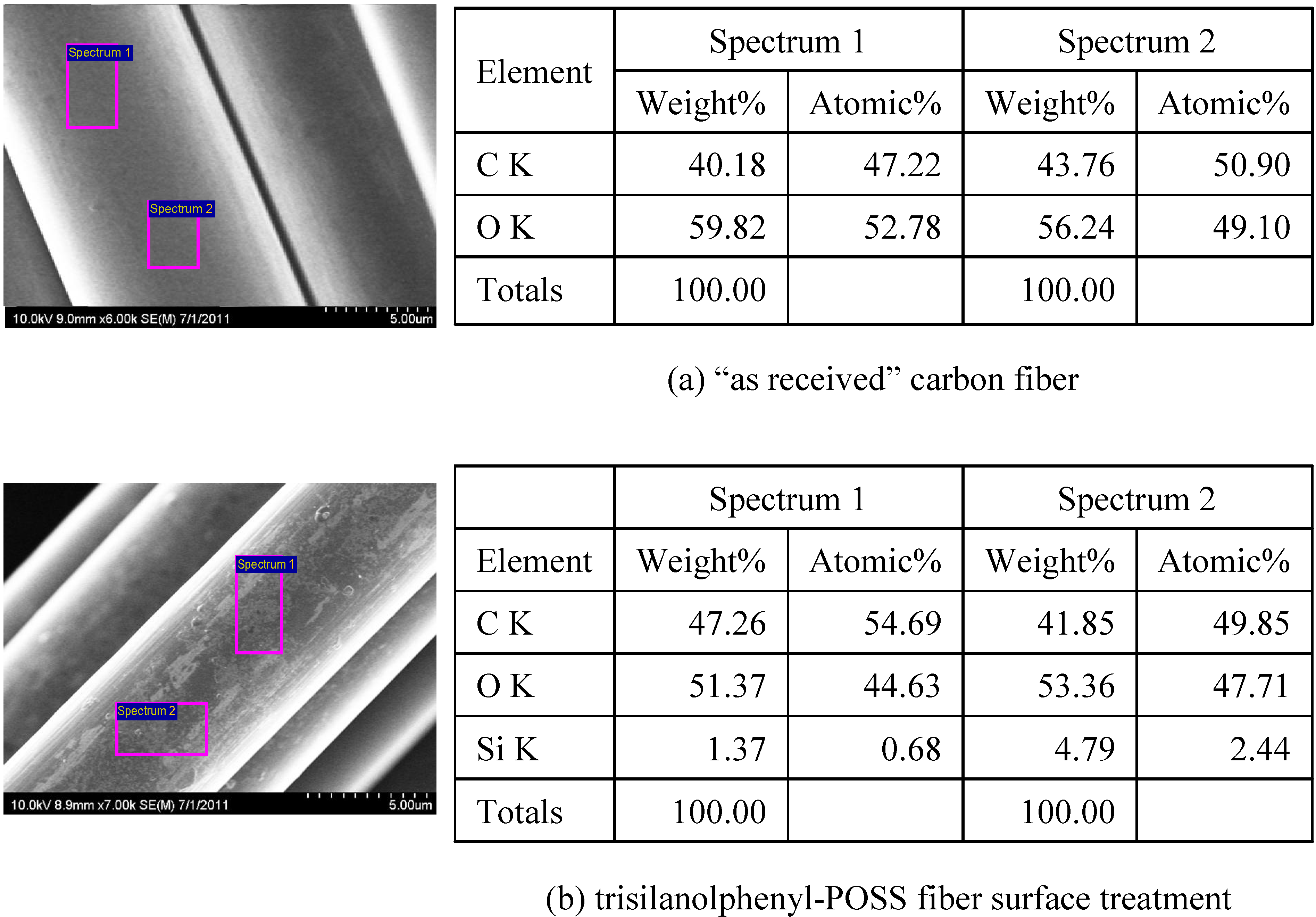
3.1. Fiber Surface Analysis

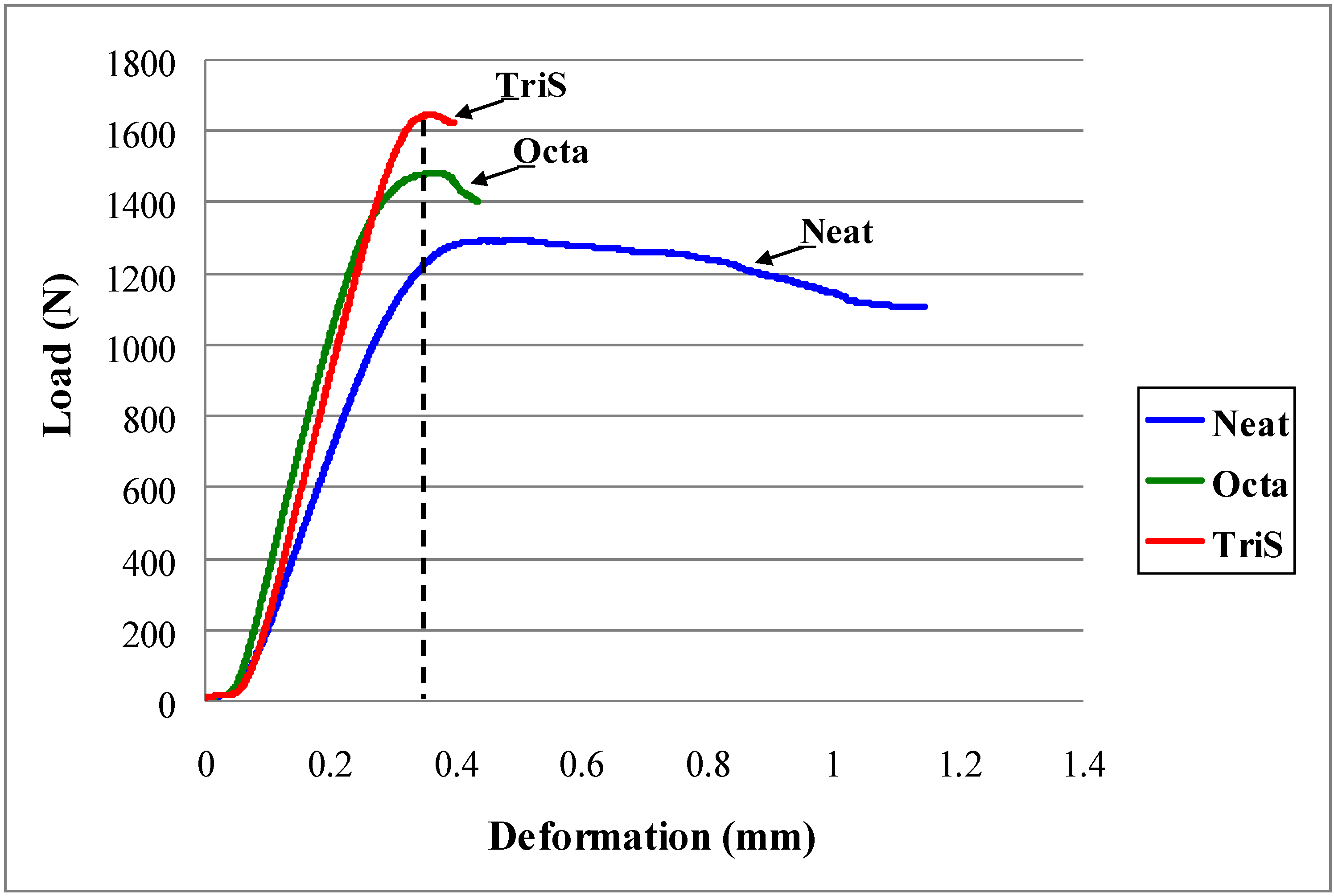
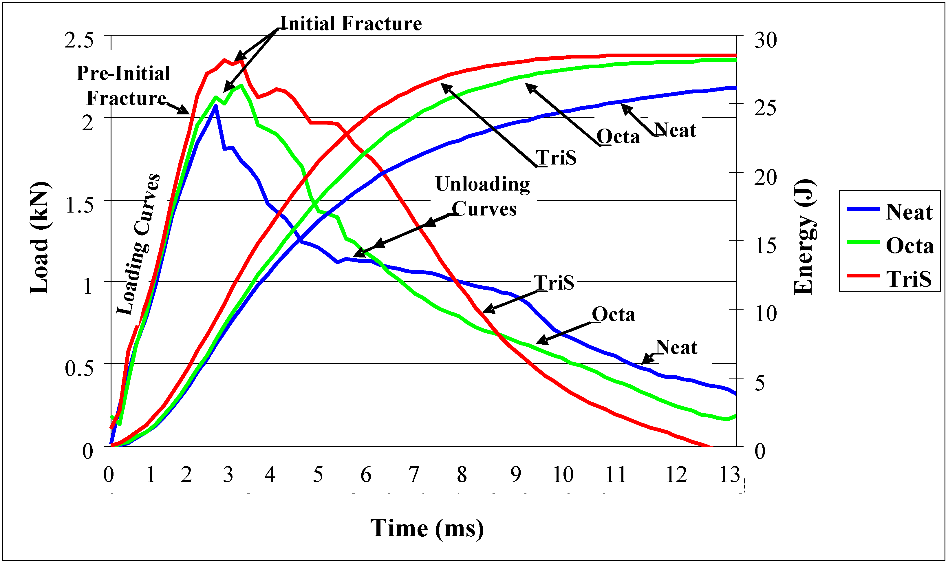
3.2. Interlaminar Shear and Low Velocity Impact Tests


| Panel Type | Carbon Fiber wt % | Shear Strength (MPa) | Gain/Loss (%) |
|---|---|---|---|
| Neat | --- | 18.38 ± 0.72 | --- |
| Octa | 1.0% | 21.51 ± 0.73 | 17.03 |
| TriS | 0.2% | 23.06 ± 1.82 | 25.48 |
| Impact Parameters at Peak Load | Fiber Sizing Agent | ||||
|---|---|---|---|---|---|
| Neat | Octa | G/L* | TriS | G/L* | |
| Load (kN) | 2.14 | 2.26 | 5.61 | 2.51 | 17.3 |
| Energy (J) | 8.22 | 8.45 | 2.80 | 11.4 | 38.3 |
| Deflection (mm) | 6.79 | 6.71 | −1.18 | 7.85 | 15.6 |
| Time to Peak (ms) | 2.37 | 2.35 | −0.84 | 2.81 | 18.6 |
| Front Damage (m2) | 6.02 | 4.70 | 21.80 | 4.27 | 29.03 |
| Back Damage (m2) | 4.32 | 2.49 | 42.40 | 2.05 | 52.63 |

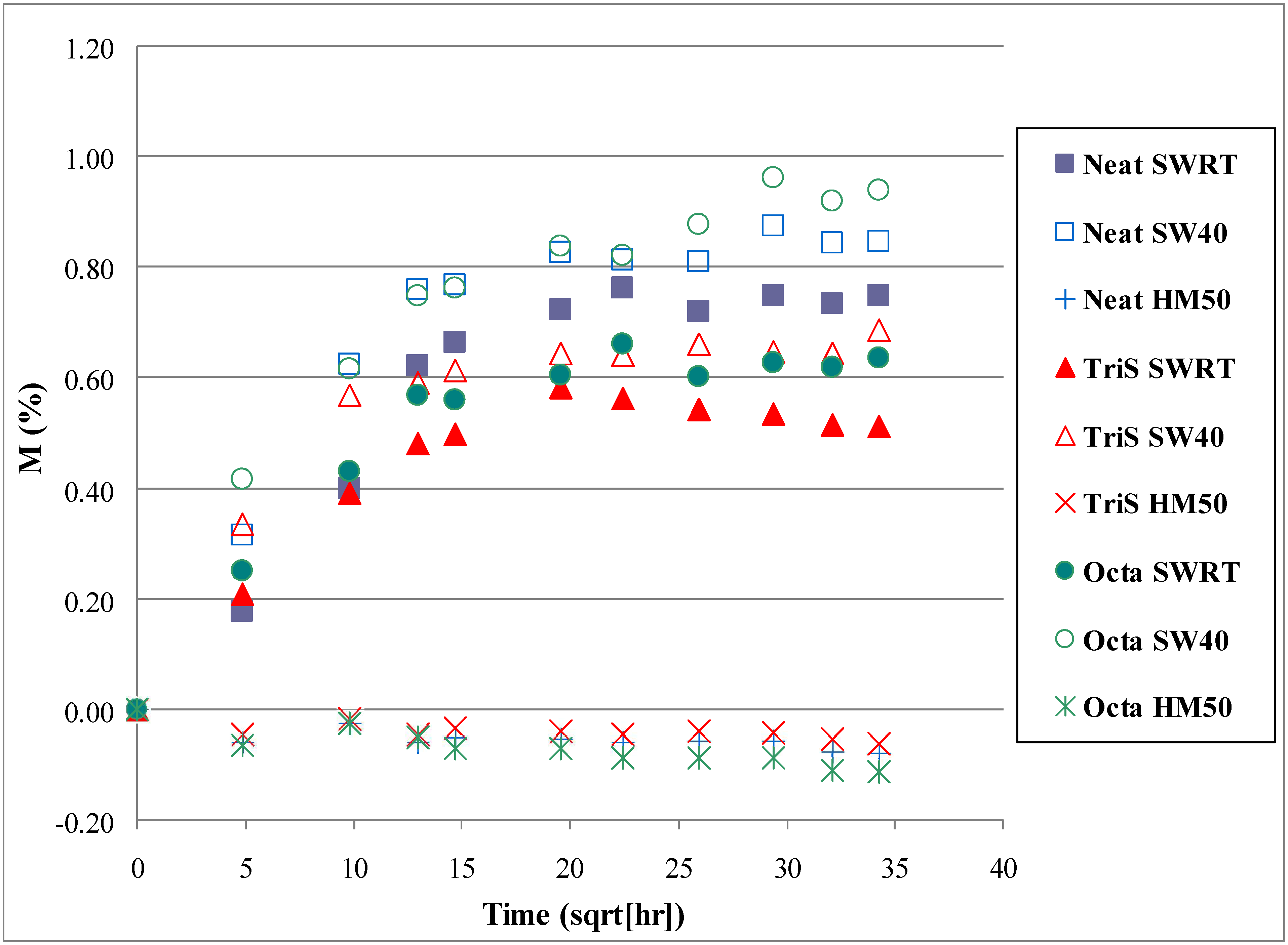
3.3. Moisture Analysis

| Condition | Percentage of Weight Change (%) | Gain/Loss w.r.t Neat (%) | |||
|---|---|---|---|---|---|
| Neat | Octa | TriS | Octa | TriS | |
| SWRT | 0.75 | 0.64 | 0.51 | 15 | 32 |
| SW40 | 0.85 | 0.94 | 0.68 | −11 | 20 |
| HM50 | - | - | - | ||
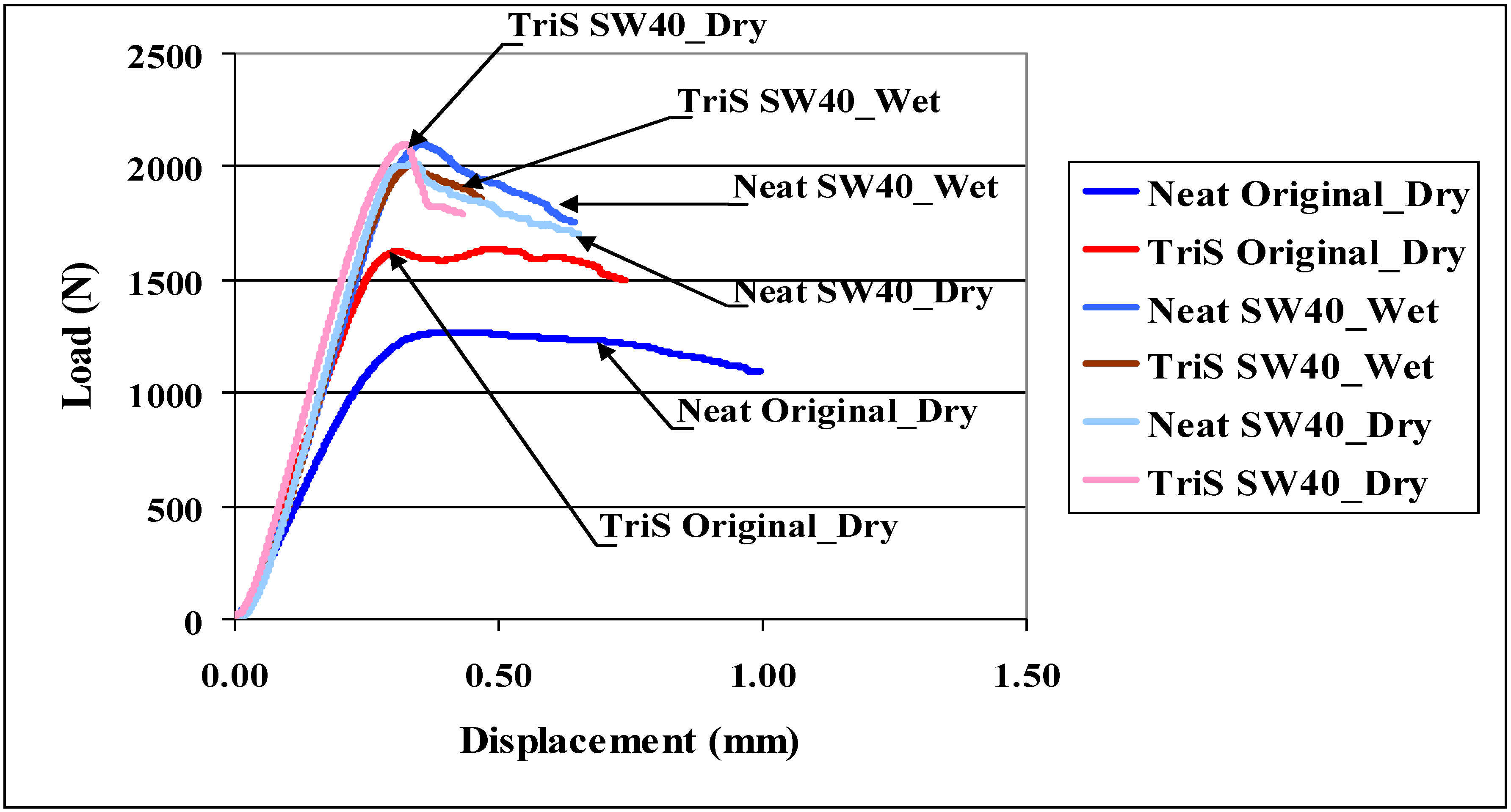
| Shear Strength (MPa) | |||
|---|---|---|---|
| Specimens | Original_Dry | SW40_Wet | SW40_Dry |
| Neat | 18.38 ± 0.72 | 29.29 ± 1.35 | 29.58 ± 1.07 |
| TriS | 21.51 ± 0.73 | 28.64 ± 1.56 | 30.30 2.16 |
4. Summary
Acknowledgement
References
- Mouritz, A.P.; Gellert, E.; Burchill, P.; Challis, K. Review of Advanced Composite Structures for Naval Ship and Submarines. Compos. Struct. 2001, 53, 21–41. [Google Scholar] [CrossRef]
- Makinen, K.; Hellbratt, S.E.; Olsson, K.A. Mechanics of Sandwich Structures; Vautrin, A., Ed.; Kluwer Academic Publishers: Dordrecht, The Netherlands, 1988; Volume 13. [Google Scholar]
- Goublat, P.; Mayes, S. Comparitive Analysis of Metal and Composite Materials for the Primary Structure of Patrol Boat. J. Nav. Eng. 1996, 108, 387–397. [Google Scholar] [CrossRef]
- Shivakumar, K.N.; Swaminathan, G.; Sharpe, M. Carbon/Vinyl Ester Composites for Enhanced Performance in Marine Applications. J. Reinf. Plast. Compos. 2006, 25, 1101–1116. [Google Scholar] [CrossRef]
- Kootsookos, A.; Mouritz, A.P. Seawater Durability of Glass- and Carbon- Polymer Composites. Compos. Sci. Technol. 2004, 64, 1503–1511. [Google Scholar] [CrossRef]
- Rivera, J.; Karbhari, V.M. Cold-Temperature and Simultaneous Aqueous Environment Related Degradation of Carbon/Vinyl Ester Composites. Compos. Part B Eng. 2002, 33, 17–24. [Google Scholar] [CrossRef]
- Acha, B.A.; Carlsson, L.A.; Granata, R.D. Moisture Effects on Carbon/Vinyl Ester by Dynamic Mechanical Analysis. In Proceedings of the ECCOMAS Thematic Conference on Mechanical Response of Composites, Porto, Portugal, 12–14 September 2007.
- Ramirez, F.A. Evaluation of water degradation of vinyl ester and epoxy matrix composites by single fiber and composite tests. M.S. Thesis, Florida Atlantic University, Boca Raton, FL, USA, 2008. [Google Scholar]
- Wood, C.A.; Bradley, W.L. Determination of the Effect of Seawater on the Interfacial Strength of an Interlayer E-glass/Graphite/Epoxy Composite by In situ Observation of Transverse Cracking in an Environmental SEM. Compos. Sci. Technol. 1997, 57, 1033–1043. [Google Scholar] [CrossRef]
- Zhu, J.; Imam, A.; Crane, R.; Lozano, K.; Khabashesku, V.; Barrera, E. Processing a glass fiber reinforced vinyl ester composite with nanotube enhancement of interlaminar shear strength. Compos. Sci. Technol. 2007, 67, 1509–1517. [Google Scholar] [CrossRef]
- Allerd, R.E.; Haight, A.E.H.; Gosau, J.M.; Wesson, S.P. Aqueous-Based Emulsion Reactive Finishes for Improving Carbon/Vinyl Ester Interfacial Bonding. In Proceedings of the 50th International SAMPE Symposium and Exhibition, Long Beach, CA, USA, 1–5 May 2005.
- Park, R.; Jang, J. Performance improvement of carbon fiber/polyethylene fiber hybrid composites. J. Mater. Sci. 1999, 34, 2903–2910. [Google Scholar] [CrossRef]
- Langston, T.A. The Effects of Nitric Acid and Silane Surface Treatments on Carbon Fibers and Carbon/Vinyl Ester Composites Before and After Seawater Exposure. Ph.D. Dissertation, Florida Atlantic University, Boca Raton, FL, USA, 2008. [Google Scholar]
- Verghese, K.N.E.; Broyles, N.S.; Lesko, J.J.; Davis, R.M.; Riffle, J.S. Pultruded Carbon Fiber/Vinyl Ester Composites Processed with Different Fiber Sizing Agents. Part II: Enviro-Mechanical Durability. J. Mater. Civ. Eng. 2005, 17, 335–342. [Google Scholar]
- User’s Guide. Hybrid Plastics, a Company. 2009. Available online: http://www.hybridplastics.com/pdf/user-v2.06.pdf (accessed on 4 September 2008).
- Zhang, X.; Huang, Y.; Wang, T.; Liu, L. Effects of polyhedral oligomeric silsesquioxane coatings on the interface and impact properties of carbon fiber/polyarylacetylene composites. J. Appl. Polym. Sci. 2006, 102, 5202–5211. [Google Scholar] [CrossRef]
- Mahfuz, H.; Powell, F.; Granata, R.; Hosur, M. The Effects of POSS on the Interlaminar Shear Strength of Marine Composites under Various Environmental Conditions. In Proceedings of the 2010 Nanotech Conference, Anaheim, CA, USA, 21–23 June 2010; Volume 115.
- Mahfuz, H.; Powell, F.; Granata, R.; Hosur, M. Treatment of Carbon Fiber with POSS and Enhancement in Mechanical Properties of Composites. In Proceedings of the Society for the Advancement of Material and Process Engineering, Seattle, WA, USA, 17–20 May 2010.
- Hosur, M.V.; Jain, K.; Chowdhury, F.; Jeelani, S.; Bhat, M.R.; Murthy, C.R.L. Low-velocity impact response of carbon/epoxy laminates subjected to cold-dry and cold-moist conditioning. Compos. Struct. 2007, 79, 300–311. [Google Scholar] [CrossRef]
- Shen, C.; Spring, G.S. Moisture Absorption and desorption of composite materials. J. Compos. Mater. 1976, 10, 2–20. [Google Scholar] [CrossRef]
- Rodgers, R.; Mahfuz, H.; Rangari, V.; Chisholm, N.; Jeelani, S. Infusion of nanoparticle into SC-15 epoxy; an investigation of thermal and mechanical response. Macromol. Mater. Eng. 2005, 290, 423–429. [Google Scholar] [CrossRef]
- Chisholm, N.; Mahfuz, H.; Rangari, V.; Ashfaq, A.; Jeelani, S. Fabrication and mechanical characterization of carbon/epoxy nanocomposites. Compos. Struct. 2005, 67, 115–124. [Google Scholar] [CrossRef]
- Cantwell, W.J.; Morton, J. Comparison of low and high velocity impact response of CFRP. Composites 1989, 20, 545–551. [Google Scholar] [CrossRef]
- Nejhad, M.N.G.; Parvizi-Majidi, A. Impact behavior and damage tolerance of woven carbon reinforced thermoplastic composites. Composites 1990, 21, 155–168. [Google Scholar] [CrossRef]
© 2011 by the authors; licensee MDPI, Basel, Switzerland. This article is an open access article distributed under the terms and conditions of the Creative Commons Attribution license (http://creativecommons.org/licenses/by/3.0/).
Share and Cite
Mahfuz, H.; Powell, F.; Granata, R.; Hosur, M.; Khan, M. Coating of Carbon Fiber with Polyhedral Oligomeric Silsesquioxane (POSS) to Enhance Mechanical Properties and Durability of Carbon/Vinyl Ester Composites. Materials 2011, 4, 1619-1631. https://doi.org/10.3390/ma4091619
Mahfuz H, Powell F, Granata R, Hosur M, Khan M. Coating of Carbon Fiber with Polyhedral Oligomeric Silsesquioxane (POSS) to Enhance Mechanical Properties and Durability of Carbon/Vinyl Ester Composites. Materials. 2011; 4(9):1619-1631. https://doi.org/10.3390/ma4091619
Chicago/Turabian StyleMahfuz, Hassan, Felicia Powell, Richard Granata, Mahesh Hosur, and Mujib Khan. 2011. "Coating of Carbon Fiber with Polyhedral Oligomeric Silsesquioxane (POSS) to Enhance Mechanical Properties and Durability of Carbon/Vinyl Ester Composites" Materials 4, no. 9: 1619-1631. https://doi.org/10.3390/ma4091619