Accelerated Iterative Learning Control of Speed Ripple Suppression for a Seeker Servo Motor


School of Automation, Northwestern Polytechnical University, Xi’an 710029, China
*
Author to whom correspondence should be addressed.
Algorithms 2018, 11(10), 152; https://doi.org/10.3390/a11100152
Submission received: 10 September 2018
/
Revised: 28 September 2018
/
Accepted: 2 October 2018
/
Published: 10 October 2018
Abstract
:To suppress the speed ripple of a permanent magnet synchronous motor in a seeker servo system, we propose an accelerated iterative learning control with an adjustable learning interval. First, according to the error of current iterative learning for the system, we determine the next iterative learning interval and conduct real-time correction on the learning gain. For the learning interval, as the number of iterations increases, the actual interval that needs correction constantly shortens, accelerating the convergence speed. Second, we analyze the specific structure of the controller while applying reasonable assumptions pertaining to its condition. Using the λ-norm, we analyze and apply our mathematical knowledge to obtain a strict mathematical proof on the P-type iterative learning control and obtain the condition of convergence for the controller. Finally, we apply the proposed method for periodic ripple inhibition of the torque rotation speed of the permanent magnet synchronous motor and establish the system model; we use the periodic load torque to simulate the ripple torque of the synchronous motor. The simulation and experimental results indicate the effectiveness of the method.
1. Introduction
The permanent magnet synchronous motor has the advantages of high efficiency, high power density, and a high torque inertia ratio [1] and has been widely applied to the fields of aerospace, robotics, and transportation [2,3,4,5]. In recent years, as the requirements for system performance and accuracy have increased, how to suppress the speed ripple of the permanent magnet synchronous motor has become an active research area. In particular, in the direct drive system, because there is no transmission link involving gears, the rotation speed of the motor is relatively low, and the problems of low-frequency noise and vibration caused by the speed ripple are more severe. The torque ripple is the main source of the speed ripple. Based on extensive study, researchers worldwide have proposed multiple methods to suppress the torque ripple of the permanent magnet synchronous motor, which are mainly divided into two classes: Improving the main body design of the motor and optimizing the design of the software control algorithm.
The methods to improve the main body of the motor involve the stator slot [6], fractional slot [7], and toothless stator structure [8]. These methods can attenuate the speed ripple to some extent, but the design challenges are numerous, and the design cost is high. Regarding the aspect of software control, a previous study [9] adopted an adaptive filter to filter the feedback current and improve the performance of the current loop. Based on a PI controller, Zhang et al. [10] superimposed an oscillating controller and used the torque current, generated by this controller, to counteract the load torque ripple. Chu et al. [11] adopted a speed-loop control strategy using a PI regulator and a repetitive controller in parallel. Without affecting the dynamic performance, this configuration improved the steady-state characteristics of the system and suppressed the periodic speed ripple, but no strict mathematical proof was given to ensure convergence. Another study [12] proposed a method based on the optimization of the voltage vector that improved the model predictive control and adopted duty cycle control, thus reducing the torque ripple, but the parameter selection of the cost function was found to be relatively challenging.
Iterative learning control [13,14,15] is a type of model-less control with a simple structure that does not need specific model parameters. Over a limited interval, only through a sufficient number of repeated iterations can the behavior of the execution object satisfy the expected requirements. Iterative learning control has important significance for situations with nonlinearity, strong coupling, challenging modeling, and the requirement of high-accuracy trajectory control [16]. The existing studies on the theory of iterative learning control concentrate mainly on proofs of convergence for the learning algorithm, the learning velocity, studies of the structural form for the learning law, the robustness of, and analysis method, for the iterative learning process, the initial values, and assorted engineering applications [17,18,19,20,21,22,23]. There have been few studies on iterative learning control of the servo system for the permanent magnet synchronous motor. Li et al. [24] proposed to adopt the method of cascade iterative learning control to revise the reference input signal and improve the system accuracy by iteratively correcting the reference input. Another study [25] combined sliding mode control and iterative learning and proposed a robust iterative learning control strategy using a performance weighting function to improve the system robustness.
In this paper, to address the speed ripple of a permanent magnet synchronous motor, we propose an accelerated iterative learning control. The characteristics of the proposed method are as follows: For the learning interval of this control, as the number of iterations increases, the actual interval that needs correction constantly shortens, which accelerates the convergence speed. In this time interval, we conduct real-time correction of the learning gain. Outside the correction interval, the error is within the allowable range; there is no need for correction, and we directly apply the learned control input. That is, we constantly shorten the learning interval until learning is completed. This method reduces the overall computation amount by accelerating the learning speed. The proposed method not only accelerates the speed of iterative learning but also increases the tracking accuracy of the system. In this paper, we give a strict mathematical proof and verify the effectiveness and accuracy of the theory through simulation and experiment.
2. Description and Analysis of the Question
Consider a class of nonlinear systems:
where ; is the number of iterations; , , and are the state variables, control variables, and output variables of the system, respectively; and , , and are the matrices of the corresponding dimension.
Control objective: Design a controller for the system and let the system output track the expected trajectory under this controller.
For the convenience of proof, we make reasonable assumptions for the algorithm:
Assumption 1.
The unknown nonlinear functionsatisfies the Lipschitz condition, namely, there is a constantthat satisfies
Assumption 2.
There is an ideal controlthat makes the state and output of the system be the expected values ofand , respectively.
In the method proposed in this paper, we divide the interval into N equal sub-intervals, each with length .
Let
We presume that the controlled object (1) adopts the P-type learning law:
where is the proportional learning gain, is the exponential correction factor, and is the cut-off time (note: in the th iteration, the error in interval satisfies the allowable range, and the error in the residual interval does not satisfy the allowable range).
Let be the indicative function, namely,
According to Equation (4), Equation (5) can be rewritten as
For the aforementioned accelerated P-type iterative learning control, which is constructed with gain correction, the learning control law is described as follows: We presume that the initial operation input is , whose value is random in the entire operation interval . In Equation (8), the introduction of is aimed at obtaining the boundary point that needs to be learned for the next iteration selection.
The steps of this method are as following:
- Step 1: Calculate using Equation (6);
- Step 2: Calculate using Equation (7);
- Step 3: Calculate using Equation (8);
- Step 4: Calculate using Equation (9);
- Step 5: Calculate using Equation (5);
- Step 6: Ending this iteration and starting the next. And repeat step 1–5.
The structure of the control law (3) indicates that the interval that has been learned previously does not require continued learning, and we only need to learn the interval of the expected trajectory that is not completely tracked. As the number of iterations increases, the required length of the learning interval gradually approaches zero. The controller block diagram is showing as Figure 1.
Lemma 1.
(Bellman-Gronwall inequality) [26]: Let , , andbe nonnegative continuous functions in interval . Moreover, there is a nonnegative constantthat satisfies.
Thus,
Theorem 1.
If the system described by Equations (1) and (3) satisfies the conditions
- (I)
- and
- (II)
- ,
then
when , the output of systemconverges to the expected trajectoryin , i.e.,
Proof.
We presume that at the (k + 1)th iteration, the control time point stops at ; Equation (6) indicates that . Therefore, when , the error can be expressed as
When , from Equation (1) and condition (II), we obtain Equation (12):
Rewritten Equation (12) as
We take the norm on both sides of Equation (13) and multiply by , . Moreover, we take the maximum on and combine it with the Lipschitz condition to obtain
Here,
From Equation (1), we obtain
We take the norm on both sides of Equation (15) and use the Lipschitz condition to obtain
From the Bellman-Gronwall inequality, we obtain
We multiply both sides of the equation above by , where , and take the maximum on to obtain
where .
In interval , we introduce Equation (18) into Equation (14) to obtain
We select a sufficiently large and let
After numbers of iterations, we obtain
Therefore,
This result indicates that control law (3) adopts the appropriate scheme to shorten the learning interval and ensure monotonic convergence under the -norm. When is sufficiently large, as the number of iteration increases, we track the expected trajectory in a piecewise manner and conduct real-time correction of the learning gain. Moreover, the interval length which decreases and ultimately approaches zero. Finally, over the entire interval , the system output tracks the expected trajectory. □
3. Simulation Results and Analysis
The seeker servo system can be simplified as the following control system of a permanent magnet synchronous motor:
where is the electromagnetic torque, is the load torque, is the angular position of the motor, is the angular speed of the motor, is the number of pairs, is the viscous friction coefficient, is the equivalent moment of inertia, and is the coefficient of elasticity. The output variable is , the control variable is , and the initial conditions are and . A previous study [27] noted that the influence of the torque ripple above the 6th order on the rotation speed can be neglected; thus, we focus our analysis on the 1st, 2nd, and 6th harmonic torque of the torque ripple. The load torque can be expressed as
The parameters of torque ripple are set as follows: is the average load torque, is the first harmonic content of the torque ripple, is the second harmonic content of the torque ripple, and is the sixth harmonic content of the torque ripple. The unit is Nm, and the phase of harmonic torque in the simulation is zero.
Figure 2 shows the process of tracking trajectory of the system output for the motor control system under the 1st-6th iterative learning steps. In particular, the dotted line is the expected speed, the dashed line is the tracking curve under the traditional P-type iterative learning control (), and the solid line is the tracking curve under described by Equation (3) ( and ). Figure 2a indicates that after the first iteration, the two control methods both have a relatively large error. Figure 2c shows the control effect after the third iteration. The convergence speed of the proposed method is faster, and the tracking error satisfies the system requirements. Figure 2f shows that for the traditional P-type iterative learning control, after the 6th iteration, the control effect also essentially satisfies the requirement, but the error is larger than that for the proposed method.
4. Experimental Results and Analysis
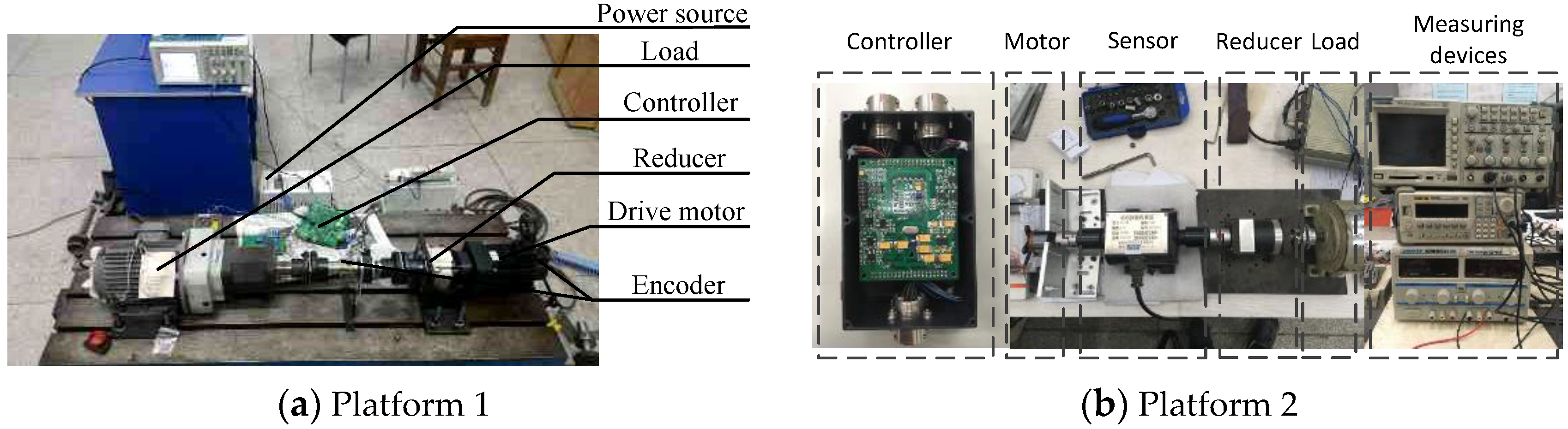
To verify the feasibility and effectiveness of the controller, we configure two experimental platforms in the laboratory (Figure 3). The proposed method is compared with the traditional PI control.
Figure 4 compares the proposed method and the traditional PI control and shows the effect of suppression under the two methods. In particular, Figure 4a shows the tracking situation of the motor angular speed. Relative to the speed closed-loop system, the periodic speed ripple exhibit relatively strong nonlinearity, and it is very challenging to completely respond only depending on the speed PI controller; moreover, the speed PI controller has some bandwidth limitations, which makes it susceptible to relatively high-order speed ripple, whereas the proposed method can satisfactorily suppress the ripple. The tracking error in Figure 4b reinforces this point.
5. Conclusions
In this paper, due to the requirements of a modern seeker servo system of fast velocity and high accuracy, we design an iterative learning control of gain correction with an adjustable learning interval. First, according to the system error of the current iteration, the next iterative learning interval is determined, and the learning gain is corrected in real time. With the increase of the number of iterations, the learning interval which needs to be corrected is shortened continuously. Then, the structure of the controller and its reasonable assumptions are analyzed. The closed loop P-type iterative learning control is strictly proved by applying the knowledge of mathematics, and the convergence condition of the controller is obtained in sense of -norm. Then, we use the P-type iterative learning law as an example and analyze the specific structure of the controller and its reasonable assumption conditions. Finally, we apply the proposed method to suppress the periodic ripple in the motor speed of the permanent magnet synchronous motor, and we establish the system model. We use the periodic load torque to simulate the ripple torque of the permanent magnet synchronous motor. The simulation and experimental results indicate the following: The proposed method not only accelerates the speed of iterative learning but also increases the tracking accuracy of the system. In upcoming studies, we plan to analyze the D-type and PD-type iterative learning control and incorporate other intelligent algorithms, such as sliding mode control, fuzzy control, and the neural network algorithm, with the accelerated iterative learning control. We can then use their respective advantages to control this complex system better.
Author Contributions
H.L. conceived the main idea of the proposed method. D.M. performed the experiments, analyzed the data and wrote the paper.
Funding
This work was funded by the National Natural Science Foundation of China (No. 51777170).
Acknowledgments
The authors would like to thank the reviewers for their constructive comments, which greatly helped to improve this paper.
Conflicts of Interest
The authors declare no conflict of interest.
References
- Ryongho, J.; Zhanshan, W.; Chaomin, L.; Myongguk, J. Adaptive robust speed control based on recurrent elman neural network for sensorless PMSM servo drives. Neurocomputing 2017, 227, 131–141. [Google Scholar]
- Slimane, M.; Demba, D.; Mohammed, M.; Claude, D.; Antoni, A. PMSM drive position estimation: Contribution to the high-frequency injection voltage selection issue. IEEE Trans. Energy Convers. 2015, 30, 349–358. [Google Scholar]
- Vrkalovic, S.; Teban, T.A.; Borlea, I.D. Stable Takagi-Sugeno fuzzy control designed by optimization. Int. J. Artif. Intell. 2017, 15, 17–29. [Google Scholar]
- Glowacz, A. Acoustic based fault diagnosis of three-phase induction motor. Appl. Acoust. 2018, 137, 82–89. [Google Scholar] [CrossRef]
- Ramanathan, P.; Mangla, K.K.; Satpathy, S. The determination of combustion engine condition and reliability using oil analysis by MLP and RBF neural networks. Measurement 2017, 115, 557–572. [Google Scholar]
- Fan, Z.N.; Han, L.; Liao, Y.; Xie, L.D.; Wen, K.; Wang, J.; Dong, X.C.; Yao, B. Effect of damper winding and stator slot skewing structure on no-load voltage waveform distortion and damper bar heat in large tubular hydro generator. IEEE Access 2018, 6, 22281–22291. [Google Scholar] [CrossRef]
- Chung, S.U.; Kim, J.W.; Chun, Y.D.; Woo, B.C.; Hong, D.K. Fractional slot concentrated winding PMSM with consequent pole rotor for a low-speed direct drive: Reduction of rare earth permanent magnet. IEEE Trans. Energy Convers. 2015, 30, 103–109. [Google Scholar] [CrossRef]
- Min, S.G.; Sarlioglu, B. Advantages and characteristic analysis of slotless rotary pm machines in comparison with conventional laminated design using statistical technique. IEEE Trans. Transp. Electrif. 2018, 4, 517–524. [Google Scholar] [CrossRef]
- Wang, D.W.; Song, C.; Zhou, W. Adaptive filter applied in optimizing current loop of permanent magnet synchronous motor. Trans. China Electrotechn. Soc. 2014, S1, 90–94. (In Chinese) [Google Scholar]
- Zhang, W.J.; Huang, S.D.; Gao, J.; Xiao, L. Suppression of speed ripples of permanent magnetic synchronous motor for compressor application. Control Theory Appl. 2013, 48, 27–29. (In Chinese) [Google Scholar]
- Chu, J.B.; Hu, Y.W.; Huang, W.X.; Yang, J.F. Suppressing speed ripples of permanent magnetic synchronous motor based on a method. Trans. China Electrotechn. Soc. 2009, 24, 43–49. (In Chinese) [Google Scholar]
- Yin, F.B.; Hua, W.; Huang, W.T.; Zhou, Z.Q. Voltage vector optimization-based model predicted torque control of flux-reversal permanent magnet machines. Proc. CSEE 2017, 37, 6524–6533. (In Chinese) [Google Scholar]
- Arimoto, S.; Kawmura, S.; Miyazaki, F. Bettering operation of robotics by learning. J. Robot. Syst. 1984, 12, 123–140. [Google Scholar] [CrossRef]
- Lan, T.Y.; Yan, F.; Lin, H. Iterative learning control with forgetting factor for urban road network. J. Control Sci. Eng. 2017, 2017, 1–7. [Google Scholar] [CrossRef]
- Chi, R.H.; Hou, Z.S.; Xu, J.X. Adaptive ILC for a class of discrete-time systems with iteration-varying trajectory and random initial condition. Automatica 2008, 44, 2207–2213. [Google Scholar] [CrossRef]
- Lin, H.; Wang, L. Iterative Learning Control Theory; Xi’an Northwestern Polytechnical University Press: Xi’an, China, 1998. [Google Scholar]
- Deyuan, M.; Kevin, L.M. Convergence of iterative learning control for SISO non-repetitive systems subject to iteration-dependent uncertainties. Automatica 2017, 79, 167–177. [Google Scholar]
- Ardakani, M.; Khong, S.Z.; Bernhardsson, B. On the convergence of iterative learning control. Automatica 2017, 78, 266–273. [Google Scholar] [CrossRef] [Green Version]
- Liu, S.D.; Wang, J.R. Fractional order iterative learning control with randomly varying trial lengths. J. Frankl. Inst. 2017, 354, 967–992. [Google Scholar] [CrossRef]
- Altın, B.; Willems, J.; Oomen, T.; Barton, K. Iterative learning control of iteration-varying systems via robust update laws with experimental implementation. Control Eng. Pract. 2017, 62, 36–45. [Google Scholar] [CrossRef]
- Tong, D.S.; Goele, P.; Jan, S. Multi-objective iterative learning control using convex optimization. Eur. J. Control 2017, 33, 35–42. [Google Scholar]
- Chen, Y.Y.; Chu, B.; Christopher, T.F. Generalized norm optimal iterative learning control: Constraint handling. IFAC-PapersOnLine 2017, 50, 13396–13401. [Google Scholar] [CrossRef]
- Preitl, S.; Precup, R.E.; Fodor, J.; Bede, B. Iterative feedback tuning in fuzzy control systems. Theory and Applications. Acta Polytech. Hung. 2006, 3, 81–96. [Google Scholar]
- Li, B.Q.; Wu, C.; Lin, H. A high-precision position servo system of permanent magnet synchronous motors with reference input iterative learning. Proc. CSEE 2012, 32, 96–102. [Google Scholar]
- Liu, J.; Li, H.W.; Deng, Y.T. Torque ripple minimization of PMSM based on robust iterative learning control. IEEE Trans. Power Electron. 2017, 25, 2645–2660. [Google Scholar]
- Ruan, X.E.; Zhao, J.Y. Pulse compensated iterative learning control to nonlinear systems with initial state uncertainty. Control Theory Appl. 2012, 29, 993–1000. [Google Scholar]
- Rupar, U.; Lahajnar, F.; Zajec, P. Iterative-learning-based torque-ripple compensation in a transverse flux motor. IET Control Theory Appl. 2012, 6, 341–348. [Google Scholar] [CrossRef]
Figure 1.
The block diagram of the controller.

Figure 2.
Tracking curve of the motor angular speed in the simulation.


Figure 3.
Platform of the experimental system.

Figure 4.
Tracking curve of the motor angular speed in the experiment.

© 2018 by the authors. Licensee MDPI, Basel, Switzerland. This article is an open access article distributed under the terms and conditions of the Creative Commons Attribution (CC BY) license (http://creativecommons.org/licenses/by/4.0/).
Share and Cite
MDPI and ACS Style
Ma, D.; Lin, H. Accelerated Iterative Learning Control of Speed Ripple Suppression for a Seeker Servo Motor. Algorithms 2018, 11, 152. https://doi.org/10.3390/a11100152
AMA Style
Ma D, Lin H. Accelerated Iterative Learning Control of Speed Ripple Suppression for a Seeker Servo Motor. Algorithms. 2018; 11(10):152. https://doi.org/10.3390/a11100152
Chicago/Turabian StyleMa, Dongqi, and Hui Lin. 2018. "Accelerated Iterative Learning Control of Speed Ripple Suppression for a Seeker Servo Motor" Algorithms 11, no. 10: 152. https://doi.org/10.3390/a11100152
Note that from the first issue of 2016, this journal uses article numbers instead of page numbers. See further details here.