Computing Fault-Containment Times of Self-Stabilizing Algorithms Using Lumped Markov Chains †


Institute of Telematics, Hamburg University of Technology, 21073 Hamburg, Germany
†
An extended abstract of this work appeared at the 19th International Symposium on Stabilization, Safety, and Security of Distributed Systems 2017 in Boston, USA.
Algorithms 2018, 11(5), 58; https://doi.org/10.3390/a11050058
Submission received: 10 February 2018
/
Revised: 28 March 2018
/
Accepted: 2 May 2018
/
Published: 3 May 2018
(This article belongs to the Special Issue 19th International Symposium on Stabilization, Safety, and Security of Distributed Systems (SSS))
Abstract
:The analysis of self-stabilizing algorithms is often limited to the worst case stabilization time starting from an arbitrary state, i.e., a state resulting from a sequence of faults. Considering the fact that these algorithms are intended to provide fault tolerance in the long run, this is not the most relevant metric. A common situation is that a running system is an a legitimate state when hit by a single fault. This event has a much higher probability than multiple concurrent faults. Therefore, the worst case time to recover from a single fault is more relevant than the recovery time from a large number of faults. This paper presents techniques to derive upper bounds for the mean time to recover from a single fault for self-stabilizing algorithms based on Markov chains in combination with lumping. To illustrate the applicability of the techniques they are applied to a new self-stabilizing coloring algorithm.
1. Introduction
Fault tolerance aims at making distributed systems more reliable by enabling them to continue the provision of services in the presence of faults. The strongest form is masking fault tolerance, where a system continues to operate after faults without any observable impairment of functionality, i.e., safety is always guaranteed. In contrast non-masking fault tolerance does not ensure safety at all times. Users may experience incorrect system behavior, but eventually the system will fully recover. The potential of this concept lies in the fact that it can be used in cases where masking fault tolerance is too costly or even impossible to implement [1]. Self-stabilizing algorithms belong to the category of distributed algorithms that provide non-masking fault tolerance. They guarantee that systems eventually recover from transient faults of any scale such as perturbations of the state in memory or communication message corruption [2]. A critical issue is the length of the time span until full recovery. Examples are known where a memory corruption at a single process caused a vast disruption in large parts of the system and triggered a cascade of corrections to reestablish safety. Thus, an important issue for non-masking fault tolerance is the containment of the effect of faults.
A fault-containing system has the ability to contain the effects of transient faults in space and time. The goal is to keep the extent of disruption during recovery proportional to the extent of the faults. An extreme case of fault-containment with respect to space is given when the effect of faults is bounded to the set of faulty nodes. Azar et al. call this error confinement [3]. More relaxed forms of fault-containment are known as time-adaptive self-stabilization [4], scalable self-stabilization [5], strong stabilization [6], and 1-adaptive self-stabilization [7].
A configuration is called k-faulty, if in a legitimate configuration exactly k processes are hit by a fault (a configuration is called legitimate if it conforms with the specification). A large body of research focuses on fault-containment for 1-faulty configurations. Two metrics have been introduced to quantify the containment behavior in the 1-faulty case: contamination radius and containment time [8,9]. A distributed algorithm has contamination radius r if only nodes within the r-hop neighborhood of the faulty node change their state during recovery from a 1-faulty configuration. The containment time of denotes the worst-case number of rounds any execution of starting at a 1-faulty configuration needs to reach a legitimate configuration. In technical terms this corresponds to the worst case time to recover in case of a single fault. For randomized algorithms the expected number of rounds to reach a legitimate configuration corresponds to the mean time to recover (MTTR).
Over the last two decades a large number of self-stabilizing algorithms have been published. Surprisingly the analysis of the vast majority of these algorithms is confined to the worst case stabilization time starting from an arbitrary configuration. Considering the fact that these algorithms are intended to provide fault tolerance in the long run this is not the most relevant metric at all. From a practical point of view the recovery time from a 1-faulty configuration is more interesting. This statement is justified considering the fact that the probability for a 1-faulty configuration is much higher than that for a k-faulty configuration with a large value of k. The reason is that a distributed system consists of independently operating computers where transient faults such as memory faults in different computers are independent events. Considering this fact it comes as a surprise that most papers consider only arbitrary initial states (i.e., k-faulty configuration for any k) instead of focusing on 1-faulty configuration. Only in a few cases fault-containment metrics have been considered [10,11]. This is even more surprising considering the fact that the many techniques available to determine the worst case stabilization time of an algorithm, e.g., potential functions and convergence stairs, can also be used to compute the containment time.
This paper discusses a technique to analyze the containment time of randomized self-stabilizing algorithms with respect to memory and message corruption. The execution of the algorithm is modeled as a stochastic process. Let X be the random variable that represents the number of rounds the system requires to reach a legitimate configuration when started in a 1-faulty configuration. Then the MTTR of the algorithm is equal to , the expected value of X. Thus, we are interested in upper bounds for . Sometimes it is possible to derive an explicit expression for or use results about absorbing Markov chains for this purpose. These equations may be solvable with a software package based on symbolic mathematics. However, the state space explosion problem precludes success for many real world problems. An important technique for the reduction of the complexity of Markov chains is lumping [12]. Lumping is a method based on the aggregation of states that exhibit the same or similar behavior. It leads to a smaller Markov chain that retains the same performance characteristics as the original one. But often lumping is not immediately applicable because the structure of the Markov chain is too complex. In some of these cases a weaker form of lumping can lead to Markov chains with a simpler structure that can still be used to derive an upper bound for the absorption time.
The contribution of this paper is a discourse about the containment time of self-stabilizing algorithms. We present and apply techniques based on Markov chains to compute upper bounds for this metric. In particular we demonstrate how lumping can be applied to reduce the complexity of the Markov chains. To demonstrate the usability of the techniques we apply it to a new self-stabilizing coloring algorithm as a case study. We derive an absolute bound for the expected containment time and show that the variance is bounded by a surprisingly small constant independent of the network’s size. We believe that the techniques can also be applied to other algorithms.
2. Related Work
Self-stabilizing algorithms are analyzed with different techniques such as potential functions, convergence stairs, and Markov chains. The latter are particularly useful for randomized algorithms [13]. Their main drawback is that in order to set up the transition matrix the graph’s adjacency matrix must be known. This restricts the applicability of this method to small or highly symmetric instances. DeVille et al. apply model checking tools to Markov chains for cases of networks of small size () to determine the expected stabilization time [14]. An example for highly symmetric networks are ring topologies [15,16]. Fribourg et al. model randomized distributed algorithms as Markov chains using the technique of coupling to compute upper bounds for the stabilization times [15]. Yamashita uses Markov chains to model self-stabilizing probabilistic algorithms and to prove stabilization [16]. Mitton et al. consider a randomized self-stabilizing -coloring algorithm and model it in terms of urns/balls using a Markov chain to get a bound for the stabilization time [17]. Their evaluation is restricted to networks up to 1000 nodes. Crouzen et al. model faulty distributed algorithms as Markov decision processes to incorporate the effects of random faults when using a non-deterministic scheduler [18]. They used the PRISM model-checker to compute long-run average availabilities.
3. System Model
This paper uses the synchronous model of distributed computing as defined in the standard literature [2,8,19]. A distributed system is represented as an undirected graph where V is the set of nodes and is the set of edges. Let and denote the maximal degree of G. The topology is assumed to be fixed. If two nodes are connected by an edge, they are called neighbors. The set of neighbors of node v is denoted by and . Each node stores a set of variables. The values of all variables constitute the local state of a node. Let denote the set of possible local states of a node. The configuration of a system is the tuple of all local states of all nodes. denotes the set of global states. A configuration is called legitimate if it conforms with the specification. The set of all legitimate configurations is denoted by .
Nodes communicate either via locally shared memory or by exchanging messages. In the shared memory model each node executes a protocol consisting of a list of rules of the form . The guard is a Boolean expression over the variables of the node and its neighbors. The statement consists of a series of commands. A node is called enabled if one of its guards evaluates to true. The execution of a statement is called a move.
In the message passing model a node performs three actions per round: receiving messages from neighbors, executing code, and sending messages to neighbors. Direct access to the state of neighboring nodes is impossible. Two nodes u and v communicate via two link registers: u writes in its register and v reads from it and v writes in its register and u reads from it. In this model the state of a node also includes the states of its registers. This works assumes the model of distributed computation [19]. Algorithms in the model enforce a limitation on the maximum message size. Hence, with a single message only a constant number of node identifiers in the range can be transmitted.
Execution of the statements is performed in a synchronous style, i.e., all enabled nodes execute their code in every round. An execution , is a sequence of configurations, where is called the initial configuration and is the configuration after the i-th round. In other words, if the current configuration is and all enabled nodes make a move, then this yields .
Let be a distributed algorithm and a set of configurations. is called self-stabilizing with respect to if it satisfies the convergence and closure properties. The first property states that every execution of reaches after a finite number of rounds. The second property states that for all as long as no fault occurs. The worst case stabilization time of for a graph G is equal to the maximal number of rounds after which reaches a legitimate configuration of G regardless of the initial configuration under the assumption that no errors occur.
Definition 1.
A configuration of a self-stabilizing algorithm with respect to is called k-faulty if a configuration satisfying exists such that c differs from in the local states of at most k nodes.
Note that for the message passing model this definition also covers message corruption. This paper analyzes the most common fault situation: 1-faulty configurations. They arise when a single node v is hit by a memory corruption or a single message sent by v is corrupted.
The containment behavior of a self-stabilizing algorithm is characterized by the contamination radius and the containment time.
Definition 2.
Let be a self-stabilizing algorithm.
- 1.
- The containment time of denotes the worst-case number of rounds any execution of starting at a 1-faulty configuration needs to reach a legitimate configuration.
- 2.
- Let be the subgraph induced by the nodes engaged in the recovery process from a 1-faulty configuration of triggered by a fault at v. Then is called the contamination radius.
The stabilization time is an obvious upper bound for the containment time.
4. Examples
Before presenting techniques to compute these metrics we give some examples using the shared memory model to illustrate the two definitions.
4.1. Contamination Radius
Consider an algorithm in the shared memory model with contamination radius r. A single fault will not spread beyond the r-hop neighborhood of the faulty node v. In this case ; is the subgraph induced by nodes w with . As an example consider the well known self-stabilizing algorithm to compute a maximal independent set (see Algorithm 1). It uses a single variable . A configuration is legitimate if nodes with form a maximal independent set.
| Algorithm 1: Self-stabilizing algorithm to compute a MIS. |
 |
Lemma 1.
Algorithm has contamination radius two.
Proof.
Consider a 1-faulty configuration where node v is hit by a memory corruption. First suppose the state of v changed from to . Let then . If u has an neighbor with then u will not change its state during recovery. Otherwise, if all neighbors of u except v had state node u may change state during recovery. But since these neighbors of u have a neighbor with state they will not change their state. Thus, in this case only the neighbors of v may change state during recovery.
Suppose that changed from to . Then v and those neighbors of v with state can change to . Then arguing as in the first case only nodes within distance two of v may change their state during recovery. ☐
Next we consider another example: -coloring. Most distributed algorithms for this problem follow the same pattern. A node that realizes that it has selected the same color as one of its neighbors chooses a new color from a finite color palette. This palette does not include the current colors of the node’s neighbors. To be executed under the synchronous scheduler these algorithms are either randomized or use identifiers for symmetry breaking. Variations of this idea are followed in [17,20,21]. As an example consider algorithm from [20] (see Algorithm 2). has a single variable c. A configuration is legitimate if the values of variable c describe a valid -coloring. Due to its choice of a new color from the palette algorithm has contamination radius at least (see Figure 1).
| Algorithm 2: Self-stabilizing -coloring algorithm from [20]. |
 |
A minor modification of algorithm dramatically changes matters. Algorithm (see Algorithm 3) has contamination radius 1 (see Lemma 2). Note that neighbors of v that change their color during recovery form an independent set.
| Algorithm 3: Self-stabilizing -coloring algorithm . |
 |
Lemma 2.
Algorithm has contamination radius one.
Proof.
Consider a 1-faulty configuration where node v is hit by a memory corruption changing its color to a color c already chosen by at least one neighbor of v. Let . In the next round the nodes in will get a chance to choose a new color. The choices will only lead to conflicts between v and other nodes in . Thus, the fault will not spread beyond the set . With a positive probability the set will contain fewer nodes in each round. ☐
4.2. Containment Time
As the contamination radius the containment time strongly depends on the concrete structure of G. This can be illustrated with algorithm . Note that in this case can contain any subgraph H with nodes. As an example let G consist of H and an additional node v connected to each node of H. A legitimate configuration is given if the state of v is and all other nodes have state (Figure 2 left). If v changes its state to due to a fault then all nodes may change to state during the next round. Thus, there is little hope for a bound below the trivial bound. Similar arguments hold for the second 1-faulty configuration of shown on the right of Figure 2.
5. Self-Stabilizing Algorithms and Markov Chains
A self-stabilizing algorithm can be regarded as a transition systems of . In each round the current configuration is transformed into a new configuration . Each configuration of occurs with a specific probability as the new configuration . The source of randomness can have its origin in the scheduler—a probabilistic scheduler randomly selects enabled nodes to make a move—or in a random experiment within one of the rules. We assume that the scheduler and the random experiment are memory-less. Therefore, the execution of algorithm can be described by a Markov chain with state set and transition matrix , where gives the probability to move from configuration to in one round. This work uses the notation for Markov chains as introduced in [12]. For a self-stabilizing algorithm this Markov chain is denoted by . In the following we uses the terms configurations of A and states of as synonyms.
There is a close relation between the absorbing states of and the legitimate configurations of . The closure property of a self-stabilizing algorithm guarantees that a configuration of is always mapped to a configuration in , i.e., . Whereas a state of a markov chain is called absorbing if it is impossible to leave this state. Note that a non-legitimate state of cannot be an absorbing state of . In silent self-stabilizing algorithms we have for all . For non-silent algorithms we may without loss of generality also assume that for all . If this condition is not given we can partition into subsets with and identify all configurations in as corresponding to the same state. For the computation of the stabilization time this does not make a difference. Under this assumption the Markov chain is an absorbing Markov chain and the set of absorbing states corresponds to the set of legitimate states of . We can state the following easy to prove lemma.
Lemma 3.
Let c be a configuration of . An absorbing state of is reached from c in expected B steps if and only if stabilizes in expected B rounds from c.
The computation of the expected time to absorption for an absorbing Markov chain using the transition matrix P is a simple matrix operation [12]. We assume a labeling of the states such that the t non-absorbing states come before the a absorbing states. Then P has the following canonical form
Here E is a unit matrix and Q a matrix. For an absorbing Markov chain, the matrix is called the fundamental matrix for P. Let be the expected number of steps before the chain is absorbed, given that the chain starts in the i-th state, and let t be the column vector whose i-th entry is . Then , where c is a column vector all of whose entries are 1. The variance of these numbers of steps is given by the entries of where is derived from t by squaring each entry [12]. Thus, if N is the fundamental matrix of then the expected number of rounds after which algorithm stabilizes is provided, the initial configuration is randomly chosen from the non-legitimate configurations.
There is still a big obstacles to practically apply this procedure. In order to compute the matrix N the probabilities need to be known explicitly. Without knowing the graph explicitly it is impossible to compute the probabilities for all pairs of states . This is only possible for small graphs or when the graph has a symmetric structure, e.g., a ring.
The fundamental matrix contains a lot of information which is not needed for the computation of the stabilization time. Therefore, a coarser analysis of the Markov chain would be sufficient. A common approach is to partition into subsets and consider these as the states of a new Markov chain (see Figure 3). The challenge is to define the transition probabilities of the new chain in a way that allows to transfer properties of this new chain to the original one.
A partition of is called lumpable if the subsets have the property that for each pair the probability of a state to be transformed in one step into a state of is independent of the choice of (Definition 6.3.1 [12]). This probability is then interpreted as the transition probability from to . More formally, a Markov chain is lumpable with respect to partition of if for any and any
A lumpable Markov chain defines a new Markov chain with state set P and transition probabilities
The following result proved in [12] , p. 128.
Lemma 4.
Let be a state of a lumpable Markov chain . Then the expected time to reach from c an absorbing state of is equal to the expected time to reach from an absorbing state of .
The last two lemmas prove the following theorem.
Theorem 1.
Let be a self-stabilizing algorithm with Σ the set of configurations. Let be a partition of Σ with such that is lumpable with respect to P. For any i an absorbing state of is reached from in expected B steps if and only if stabilizes in expected B rounds starting in any .
Unfortunately it is rather difficult to make use of Theorem 1 under general conditions. This situations changes when the theorem is used to compute the containment time of a self-stabilizing algorithm . Remember that the containment time of denotes the worst-case number of rounds any execution of starting in a 1-faulty configuration needs to reach a legitimate configuration. Thus, the containment time of is , where v is the faulty node. There are two aspects that ease the application of Theorem 1: Either has a symmetric structure or is small.
To illustrate this approach we consider again algorithm . Let v be a node that changes in a legitimate state its color to due to a memory fault (see Figure 4). Let be the new configuration. This causes a conflict with those neighbors of v that had chosen as their color. After the fault only nodes contained in (a star graph) change their state (see Figure 4 right). Once a neighbor has chosen a color different from then it becomes passive (at least until the next transient fault).
The set is equal to the set of all configurations of reachable from . To partition this set let d be the number of neighbors of v that have color in . Let where is the subset of where exactly neighbors of v are in conflict with v. Then and . Figure 5 shows some configurations belonging to the sets , , and . Let . Then for all . Unfortunately the partition P is not lumpable because the probability of a configuration to be transformed in one round into a fixed configuration of is not independent of the choice of . But even in these cases Theorem 1 can lead to an upper bound of the stabilization time. This is proved in the following theorem.
Theorem 2.
Let be a self-stabilizing algorithm with Σ the set of configurations. Let be a partition of Σ with such that for all if then with . For let be a constant such that for all . Furthermore, let for and for . Let be the Markov chain with states P and transition matrix . If an absorbing state of is reached from in expected B steps then the expected number of rounds requires to stabilize starting in any is at most B.
Proof.
Note
for each fixed . Thus, and therefore the matrix is a stochastic with that describes the new Markov chain . Remember that denotes the markov chain corresponding to algorithm . The difference between and is that with chain a node remains with a higher probability in its current configuration instead of moving to a state with lower index. Therefore, the expected number of steps of before being absorbed is an upper bound for the corresponding number in . The choice of the probabilities implies that is lumpable for partition P. Hence, we can apply Theorem 1 to complete the proof. ☐
In the rest of this paper the introduced techniques including Theorem 2 are exemplary applied to a self-stabilizing -coloring algorithm using the message passing model.
6. Algorithm
This section introduces coloring algorithm (see Algorithm 4). Computing a -coloring in expected rounds with a randomized algorithm is long known [22,23]. Algorithm follows the pattern sketched in Section 4.1. We derived it from an existing algorithm (Algorithm 19 [24]) by adding the self-stabilization property. The presented techniques can also be applied to other randomized coloring algorithms such as [17,20,21]. The main difference is that assumes the synchronous message passing model. Algorithm stabilizes after rounds with high probability whereas the above cited self-stabilizing algorithms all require a linear number of rounds. Since synchronous local algorithms can be converted to asynchronous self-stabilizing algorithms [25], there are self-stabilizing -coloring algorithms faster than . However, they entail a burden on memory resources and cause high traffic costs.
At the start of each round each node broadcasts its current color to its neighbors. Based on the information received from its neighbors a node decides either to keep its color (final choice), to choose a new color or no color (value ⊥). In particular, with equal probability a node v draws uniformly at random a color from the set or indicates that it made no choice (see function randomColor). Here, is the set of colors of neighbors of v that already made their final choice.
| Algorithm 4: Algorithm as executed by a node v in each round. |
 |
In the original algorithm a node maintains a list with the colors of those neighbors that made their final choice. A fault changing this list is difficult to contain. Furthermore, in order to notice a memory corruption at a neighbor, each node must continuously send its state to all its neighbors and cannot stop to do so. This is the price of self-stabilization and well known [2]. These considerations lead to the design of Algorithm . Each node only maintains the chosen color and whether its choice is final (variables c and final). In every round a node sends the values of c and final to all neighbors. uses two additional variables tabu and occupied. They are reset at the beginning of every round. To improve fault containment a node’s final choice of a color is only withdrawn if it coincides with the final choice of a neighbor. To achieve a -coloring a node makes a new choice if its color is larger than its degree. This situation can only originate from a fault.
First we prove correctness and analyze the stabilization time of . A configuration is called a legal coloring if the values of variable c form a -coloring. It is called legitimate if it is a legal coloring and for each node v.
Lemma 5.
A node v can change the value of variable from to only in the first round or when a fault occured just before the start of this round.
Proof.
Let at the beginning of the round. In order for v to set to one of the following conditions must be met at the start of the round: , , or v has a neighbor w with and .
The lemma is obviously true in the first case. Suppose that and at the round’s start. If during the previous round was set to then can not be ⊥ at the start of this round. Hence, at the start of the previous round already had value . But in this case was not changed in the previous round and thus, , contradiction. Finally assume the last condition. Then v and w cannot have changed their value of c in the previous round, because then would be impossible at the start of this round. Thus, v sent in the previous round. Hence, if at that time, w would have changed to , again a contradiction. ☐
Lemma 6.
A node setting to will not change its variables as long as no error occurs.
Proof.
Let v be a node that executes . If v changes the value back to in a later round then by Lemma 5 a fault must have occured. Thus in an error-free execution node v will never change variable again. Since a node can only change variable c if the proof is complete. ☐
Lemma 7.
If at the end of a round during which no error occured each node v satisfies then the configuration is legitimate and remains legitimate as long as no error occurs.
Proof.
Note that no node changed its color during that round. If at the start of the round was already satisfied then none of v’s neighbors also having had the same color as v. Next consider a neighbor w of v with at the start of the round. Since v sent at the start of this round, node w would have set to if it had chosen the same color as v. Contradiction. Finally consider that case that at the start of the round. Since v changed to , none of its neighbors had chosen the same color as v. Thus, the configuration is legitimate. Obviously, this property can only be changed by a fault. ☐
With these lemmas the next theorem is proved along the same lines as Lemma 10.3 in [24].
Theorem 3.
Algorithm is self-stabilizing and computes a -coloring within rounds with high probability (i.e., with probability at least for any ). has contamination radius 1.
Proof.
According to Lemma 7 it suffices to prove that all nodes terminate within time with high probability. Let . Lemma 6 implies that the probability that v terminates in round is equal to the probability that v sets to in round . This is the probability that v selects a color different from ⊥ and from the selections of all neighbors that chose a value different from ⊥ in round . Suppose that indeed at the end of round . Then . The probability that a given neighbor u of v selects the same color in this round is at most . This is because the probability that u selects a color different from ⊥ is , and v has different colors to select from. Since all nodes in have and will never change this value. Thus, at most neighbors select a new color. By the union bound, the probability that v selects the same color as a neighbor is at most
Thus, if v selects a color , it is distinct from the colors of its neighbors with probability at least . It holds that with probability . Hence, v terminates with probability at least .
The probability that a specific node v doesn’t terminate within r rounds is at most . By the union bound, the probability that there exists a vertex that does not terminate within r rounds is at most . Hence, terminates after rounds, with probability at least (note that ). ☐
6.1. Fault Containment Time of Algorithm
There is a significant difference between the shared memory and the message passing model when analyzing the containment time. Firstly, a 1-faulty configuration also arises when a single message sent by a node v is corrupted. Secondly, this may cause v’s neighbors to send messages they would not send in a legitimate configuration. Even though the states of nodes outside do not change, these nodes may be forced to send messages. Thus, in general the analysis of the containment time cannot be performed by considering only. This is only possible in cases when a fault at v does not force nodes at distance to send messages they would not send had the fault not occurred.
In the following the fault containment behavior of for 1-faulty configurations is analyzed. Two types of transient errors are considered:
- A single broadcast message sent by v is corrupted. Note that the alternative of using unicast messages instead a single broadcast has very good fault containment behavior but is slower due to the handling of acknowledgements.
- Memory corruption at node v, i.e., the value of at least one of the two variables of v is corrupted.
The first case is analyzed analytically whereas for the second case Markov chains and lumping, (Theorem 2) are used. The independent degree of a node v is the size of a maximum independent set of . Let .
6.2. Message Corruption
If a message broadcast by v contains a color different from or the value for variable then the message has no effect on any regardless of the value of , since for all . Thus, this corrupted message has no effect at all. In order to compute the containment time for we first compute the contamination radius.
Lemma 8.
The contamination radius of algorithm after a single corruption of a broadcast message sent by node v is 1. At most nodes change their state during recovery.
Proof.
It suffices to consider the case that v broadcasts message with . Let . The nodes in form an independent set, because they all have the same color. Thus .
Let . This node continues to send after the fault. Thus, a neighbor of u that changes its color will not change its color to . This yields that no neighbor of u will ever send a message with as the first parameter. This is also true in case . Hence, no node outside will change its state, i.e., the contamination radius is 1.
Let . When w receives the faulty message it sets to false. Before the faulty message was sent no neighbor of v had the same color as v. Thus, in the worst case a node will choose as its new color and send to all neighbors. Since , this will not force state to change at v. Thus, v keeps broadcasting and no neighbor w of v will ever reach the state and . Hence, v will never change its state. ☐
With this result Theorem 3 implies that the containment time of this fault is on expectation. The following theorem gives a bound for the expected value of the containment time including its variance. Since the variance of a random variable is the expected value of the squared deviation from the mean, this theorem shows that the containment time does not deviate much from its expected value. A concrete bound can be obtained from this result using Chebyshev’s inequality.
Theorem 4.
The expected containment time of algorithm after a corruption of a message broadcast by node v is at most rounds ( is the harmonic number) with a variance of at most
Proof.
After receiving message all nodes set to and with equal probability to ⊥ or to a random color . Note that because . At the end of the round during which the corrupted message was received, node w can choose v’s current color, because it may not be contained in the set . This can not happen in the following rounds. Thus, if w chooses a color different from ⊥ in the following rounds then this color is different from the colors of all of w’s neighbors. Also in this case w will terminate after the following round because then it will set to . Thus, after one round w has chosen a color that is different from the colors of all neighbors with probability at least . Furthermore, this color will not change again. After one additional round w reaches a legitimate state.
Let the random variable with denote the number of rounds until the system has reached a legal coloring. For let be the random variable denoting the number of rounds until w has a legal coloring. By Lemma 8 . For let . Since the random variables ’s are independent where X is a geometric random variable with . Thus and
Then . Let . Now for
This implies
The result follows from Lemma 9. The expression for the variance is proved in Lemma 10. ☐
Lemma 9.
For fixed and fixed
Proof.
The function is for fixed values of d decreasing for . Furthermore, . Hence,
Using the substitution the integral becomes
Approximating with yields
☐
Lemma 10.
For the variance of the containment time is at most
Proof.
By Lemma 11
Now Lemma 12 and Lemma 4 yield
☐
Lemma 11.
Let , and . Then
Proof.
For the first equation we refer to the proof of Theorem 4. The second equality makes use of
and the fourth equality uses the following two identities
☐
Lemma 12.
Let and then
Proof.
We approximate with . Note that has a single local maximum in the interval . If the local maximum is within the interval with then the error is
This leads to a small overestimation of the sum as Figure 6b shows.
The first equation uses the substitution . The final result is based on the following identity
☐
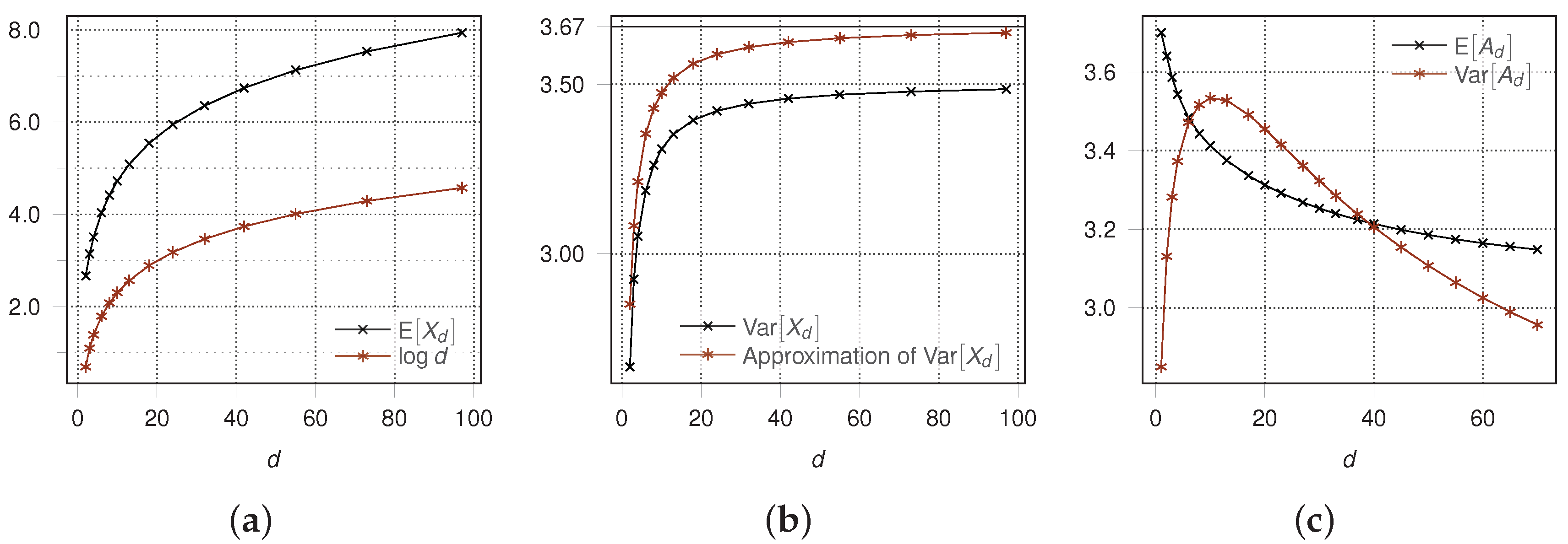
Theorem 4 gives an upper bound for the containment time and its variance of algorithm . To evaluate the quality of these upper bounds we modeled the behavior of this fault situation as a Markov chain and computed and using a software package based on symbolic mathematics. Using Theorem 3.3.5 from [12] these computations showed that matches very well with and that (see Figure 6a). Furthermore, the gap between and the bound given in Theorem 4 is less than (see Figure 6b).
6.3. Memory Corruption
This section demonstrates the use of Markov chains and the application of Theorem 2. We consider the case that the memory of a single node v is hit by a fault. The analysis breaks down the stabilizing executions into several states and then computes the expected time for each of these phases. First we look at the case that the fault causes variable to change to . If does not change, then a legitimate configuration is reached after one round. So assume also changes. Then the fault will not affect other nodes. This is because no will change its value of since and . Thus, with probability at least node v will choose in the next round a color different from the colors of all neighbors and terminate one round later. Similar to let random variable denote the number of rounds until a legal coloring is reached (). It is easy to verify that in this case.
The last case is that only variable is affected (i.e., remains ). The main difference to the case of a corrupted message is that this fault persists until has again a legitimate value. Let be the corrupted value of and suppose that . A node outside will not change its state (cf. Lemma 8). Thus, the contamination radius is 1 and at most nodes change state. Let . The subgraph induced by S is a star graph with nodes and center v.
Lemma 13.
To find a lower bound for we may assume that w can choose a color from with if and otherwise and v can choose a color from with .
Proof.
When a node chooses a color with function randomColor the color is randomly selected from . Thus, if w and v choose colors in the same round, the probability that the chosen colors coincide is . This value is maximal if is maximal and is minimal. This is achieved when and is minimal (independent of the size of ) or vice versa. Thus, without loss of generality we can assume that and both sets are minimal. Thus, for the nodes in already use all colors from but 0 and 1 and all nodes in already use all colors from but . Hence, a node can choose a color from with if and otherwise. Furthermore, v can choose a color from with . In this case if for all . ☐
Thus, in order to bound the expected number of rounds to reach a legitimate state after a memory corruption we can assume that and and (i.e., ) for all . After one round for all . To apply Theorem 2 the set of all configurations is partitioned into subsets as follows:
- I:
- Represents the faulty state with and for all .
- :
- Node v and exactly non-center nodes will not be in a legitimate state after the following round (). In particular and or for exactly non-center nodes w.
- P:
- Node v has not reached a legitimate state but will do so in the next round. In particular and for all non-center nodes w.
- F:
- Node v is in a legitimate state, i.e., and for all non-center nodes w, but may be equal to ⊥.
Note that I is the initial and F the absorbing state of the lumped Markov chain. Also when the system is in state F, then it is not necessarily in a legitimate state. This state reflects the set of configurations considered in the last section.
Lemma 14.
Table 1 describes the transition probabilities of the lumped Markov chain.
Proof.
We consider each case separately. The last two cases are trivial.
- Note that and for all .Case 0: . Impossible.Case 1: . Impossible, since non-center nodes have and .Case 2: . This happens with probability . All non-center nodes w choose , this happens with probability .Case 3: . This happens with probability . Non-center nodes can make any choice. This gives the total probability for this transition as
- Note that and for all .Case 0: . Non-center nodes choose . The case has probabilityCase 1: . Impossible (see transition ).Case 2: . At least one non-center nodes w choose , all others choose . This case has probability .Case 3: . This case is impossible.
- Note that for all .Case 1: . This happens with probability . None of the non-center nodes w sets , this has probability .Case 2: . Similar to case 1.Case 3: . (requires ). This happens with probability . Non-center nodes can make any choice.
- Note that for all .Case 1: . This happens with probability . non-center nodes choose (with probability ), the other non-center nodes choose (with probability ). The total probability for this case is .Case 2: . This happens with probability . Exactly non-center nodes choose (with probability ), non-center nodes choose (with probability ) and all other non-center nodes choose (with probability ). The total probability for this case isCase 2: . Similar to Case 1.Case 3: . This does not lead to but to P.
- Note that for all .Case 1: . This happens with probability . None of the non-center nodes w sets , this has probability .Case 2: . Similar to case 1.Case 3: . This happens with probability . Note . Non-center nodes can make any choice.
☐
We first calculate the expected number of rounds to reach the absorbing state F. With Theorem 4 this will enable us to compute the expected number of rounds required to reach a legitimate system state. To build the transition matrix of the lumped Markov chain the states are ordered as . Let Q be the upper left submatrix of P. For denote by the lower right submatrix of Q, i.e., . Denote by the fundamental matrix of (notation as introduced in Section 5). Let be the column vector of length whose entries are all 1 and . For , is the expected number of rounds to reach state F from state and is the expected number of rounds to reach state F from I, i.e., (Theorem 3.3.5, [12]). Identifying P with we have .
Lemma 15.
The expected number of rounds to reach F from I is at most 5 and the variance is at most .
Proof.
Note that and are upper triangle matrices. Let
gives rise to equations. Adding up the equations for the first row of results in
It is straightforward to verify that and . Hence
Next we show by induction on i that for . So assume that for with . Then
since . Using the fact this inequality becomes
Coefficient denotes the transition probability from to for and that for changing from to P. For the following values from Lemma 14 are used:
holds for . This yields
and therefore . To bound we use Equation 1 with . Note that in this case since a transition from I to itself is impossible. Hence
Thus, Figure 6c shows that . ☐
Lemma 16.
The expected containment time after a memory corruption at node v is at most with variance less than .
Proof.
For a set X of configurations and a single configuration c denote by the expected value of the number of transitions from x to a state in X. Let be the set of legitimate system states. Then
The last step uses Lemma 4 and 15. The bound on the variance is proved similarly. ☐
Theorem 3 and 4, Lemma 8 and 16 together prove the following Theorem.
Theorem 5.
is a self-stabilizing algorithm for computing a -coloring in the synchronous model within time with high probability. It uses messages of size and requires storage per node. With respect to memory and message corruption it has contamination radius 1. The expected containment time is at most with variance less than .
Corollary 1.
Algorithm has expected containment time for bounded-independence graphs. For unit disc graphs this time is at most .
Proof.
For these graphs , in particular for unit disc graphs. ☐
7. Conclusions
The analysis of self-stabilizing algorithms is often confined to the stabilization time starting from an arbitrary configuration. In practice the time to recover from a 1-faulty configuration is much more relevant. This paper presents techniques to analyze the containment time of randomized self-stabilizing algorithms for 1-faulty configurations. The execution of an algorithm is modeled as a Markov chain, its complexity is reduced with the lumping technique. The power of this technique is demonstrated by an application to a -coloring algorithm. We believe that the technique can also be applied to other self-stabilizing algorithms. We leave the application to problems such as maximal independents sets and maximal matchings for future work.
Funding
Research was funded by Deutsche Forschungsgemeinschaft DFG (TU 221/6-2).
Conflicts of Interest
The author declares no conflict of interest.
References
- Gärtner, F.C. Fundamentals of Fault-tolerant Distributed Computing in Asynchronous Environments. ACM Comput. Surv. 1999, 31, 1–26. [Google Scholar] [CrossRef]
- Dolev, S. Self-Stabilization; MIT Press: Cambridge, MA, USA, 2000. [Google Scholar]
- Azar, Y.; Kutten, S.; Patt-Shamir, B. Distributed Error Confinement. ACM Trans. Algorithms 2010, 6. [Google Scholar] [CrossRef]
- Kutten, S.; Patt-Shamir, B. Adaptive Stabilization of Reactive Protocols. In Lecture Notes in Computer Science, Proceedings of the International Conference on Foundations of Software Technology and Theoretical Computer Science, Chennai, India, 16–18 December 2004; Springer: Berlin/Heidelberg, Germany, 2004; Volume 3328, pp. 396–407. [Google Scholar]
- Ghosh, S.; He, X. Scalable Self-Stabilization. J. Parallel Distrib. Comput. 2002, 62, 945–960. [Google Scholar] [CrossRef]
- Dubois, S.; Masuzawa, T.; Tixeuil, S. Bounding the Impact of Unbounded Attacks in Stabilization. IEEE Trans. Parallel Distrib. Syst. 2012, 23, 460–466. [Google Scholar] [CrossRef]
- Beauquier, J.; Delaet, S.; Haddad, S. Necessary and sufficient conditions for 1-adaptivity. In Proceedings of the 20th International Parallel and Distributed Processing Symposium, Rhodes Island, Greece, 25–29 April 2006; pp. 10–16. [Google Scholar]
- Ghosh, S.; Gupta, A.; Herman, T.; Pemmaraju, S. Fault-containing self-stabilizing distributed protocols. Distrib. Comput. 2007, 20, 53–73. [Google Scholar] [CrossRef]
- Köhler, S.; Turau, V. Fault-containing self-stabilization in asynchronous systems with constant fault-gap. Distrib. Comput. 2012, 25, 207–224. [Google Scholar] [CrossRef]
- Ghosh, S.; Gupta, A. An exercise in fault-containment: Self-stabilizing leader election. Inf. Process. Lett. 1996, 59, 281–288. [Google Scholar] [CrossRef]
- Turau, V.; Hauck, B. A fault-containing self-stabilizing (3 ‒ 2/(Delta+1))-approximation algorithm for vertex cover in anonymous networks. Theor. Comput. Sci. 2011, 412, 4361–4371. [Google Scholar] [CrossRef]
- Kemeny, J.G.; Snell, J.L. Finite Markov Chains; Springer: Berlin/Heidelberg, Germany, 1976. [Google Scholar]
- Duflot, M.; Fribourg, L.; Picaronny, C. Randomized Finite-state Distributed Algorithms As Markov Chains. In Lecture Notes in Computer Science, Proceedings of the International Symposium on Distributed Computing, Lisbon, Portugal, 3–5 October 2001; Springer: Berlin/Heidelberg, Germany, 2001; Volume 2180, pp. 240–254. [Google Scholar]
- DeVille, R.; Mitra, S. Stability of Distributed Algorithms in the Face of Incessant Faults. In Lecture Notes in Computer Science, Proceedings of the Symposium on Self-Stabilizing Systems, Lyon, France, 3–6 November 2009; Springer: Berlin/Heidelberg, Germany, 2009; Volume 5873, pp. 224–237. [Google Scholar]
- Fribourg, L.; Messika, S.; Picaronny, C. Coupling and Self-Stabilization. Distrib. Comput. 2006, 18, 221–232. [Google Scholar] [CrossRef]
- Yamashita, M. Probabilistic Self-Stabilization and Random Walks. In Proceedings of the 2011 Second International Conference on Computing, Networking and Communications (ICNC), Osaka, Japan, 30 November–2 December 2011; pp. 1–7. [Google Scholar]
- Mitton, N.; Fleury, E.; Guérin-Lassous, I.; Séricola, B.; Tixeuil, S. On Fast Randomized Colorings in Sensor Networks. In Proceedings of ICPADS; IEEE: New York, NY, USA, 2006; pp. 31–38. [Google Scholar]
- Crouzen, P.; Hahn, E.; Hermanns, H.; Dhama, A.; Theel, O.; Wimmer, R.; Braitling, B.; Becker, B. Bounded Fairness for Probabilistic Distributed Algorithms. In Proceedings of the 11th International Conference on Application of Concurrency to System Design (ACSD), Newcastle Upon Tyne, UK, 20–24 June 2011; pp. 89–97. [Google Scholar]
- Peleg, D. Distributed Computing: A Locality-Sensitive Approach; SIAM Society for Industrial and Applied Mathematics: Philadelphia, PA, USA, 2000. [Google Scholar]
- Gradinariu, M.; Tixeuil, S. Self-stabilizing Vertex Coloring of Arbitrary Graphs. In Proceedings of the 4th International Conference on on Principles of Distributed Systems (OPODIS 2000), Paris, France, 20–22 December 2000; pp. 55–70. [Google Scholar]
- Dolev, S.; Herman, T. Superstabilizing Protocols for Dynamic Distributed Systems. Chic. J. Theor. Comput. Sci. 1997, 4, 1–40. [Google Scholar]
- Luby, M. A Simple Parallel Algorithm for the Maximal Independent Set Problem. SIAM J. Comput. 1986, 15, 1036–1055. [Google Scholar] [CrossRef]
- Johansson, Ö. Simple Distributed δ + 1-coloring of Graphs. Inf. Process. Lett. 1999, 70, 229–232. [Google Scholar] [CrossRef]
- Barenboim, L.; Elkin, M. Distributed Graph Coloring: Fundamentals and Recent Developments; Morgan & Claypool Publishers: Williston, VT, USA, 2013. [Google Scholar]
- Lenzen, C.; Suomela, J.; Wattenhofer, R. Local algorithms: Self-stabilization on speed. In Proceedings of the Symposium on Self-Stabilizing Systems, Lyon, France, 3–6 November 2009; Springer: Berlin/Heidelberg, Germany, 2009; pp. 17–34. [Google Scholar]
Figure 1.
The numbers indicate the nodes’ colors. If the left-most node is hit by a fault and changes its color to , then itself and its neighbor are enabled. With probability 0.5 the second node changes its color to . This enables the third node which changes its color to with probability 0.5. This may causes a cascade of changes in which all nodes on the horizontal line change color.

Figure 2.
1-faulty configurations of caused by a memory corruption at v. Nodes drawn in bold have state . Subgraph H correspond to . In the left graph, if node v changes to state then all nodes in H are enabled, thus the worst case stabilization time is equal to that of subgraph H. In the right graph, if node v changes to , then v and its two neighboring nodes all change to resulting in a configuration similar to the previous example.

Figure 3.
Reducing the number of states of a Markov chain.

Figure 4.
A 1-faulty configuration for algorithm where node v was hit by a fault changing its color to causing a conflict. The corresponding graph is depicted at the right side.
Figure 4.
A 1-faulty configuration for algorithm where node v was hit by a fault changing its color to causing a conflict. The corresponding graph is depicted at the right side.

Figure 5.
Elements of the partition of for a 1-faulty configuration of algorithm as described above. consists of legitimate configurations only.
Figure 5.
Elements of the partition of for a 1-faulty configuration of algorithm as described above. consists of legitimate configurations only.

Figure 6.
Comparisons of computed with approximated values from Theorems 4 and 15. (a) Comparison of computed value of with (Theorem 4); (b) Comparison of computed value of with approximation (Theorem 4); (c) and from Lemma 15.
Figure 6.
Comparisons of computed with approximated values from Theorems 4 and 15. (a) Comparison of computed value of with (Theorem 4); (b) Comparison of computed value of with approximation (Theorem 4); (c) and from Lemma 15.


Table 1.
This table summarizes the probabilities for all transitions.
| Number | Transition | Probability |
|---|---|---|
| 1 | ||
| 2 | ||
| 3 | () | |
| 4 | () | |
| 5 | () | |
| 6 | ||
| 7 | 1 |
© 2018 by the author. Licensee MDPI, Basel, Switzerland. This article is an open access article distributed under the terms and conditions of the Creative Commons Attribution (CC BY) license (http://creativecommons.org/licenses/by/4.0/).
Share and Cite
MDPI and ACS Style
Turau, V. Computing Fault-Containment Times of Self-Stabilizing Algorithms Using Lumped Markov Chains. Algorithms 2018, 11, 58. https://doi.org/10.3390/a11050058
AMA Style
Turau V. Computing Fault-Containment Times of Self-Stabilizing Algorithms Using Lumped Markov Chains. Algorithms. 2018; 11(5):58. https://doi.org/10.3390/a11050058
Chicago/Turabian StyleTurau, Volker. 2018. "Computing Fault-Containment Times of Self-Stabilizing Algorithms Using Lumped Markov Chains" Algorithms 11, no. 5: 58. https://doi.org/10.3390/a11050058
Note that from the first issue of 2016, this journal uses article numbers instead of page numbers. See further details here.