Efficient Model-Based Object Pose Estimation Based on Multi-Template Tracking and PnP Algorithms


1
Department of Electrical and Computer Engineering, Tamkang University, 151 Ying-chuan Road, Danshui District, New Taipei City 251, Taiwan
2
Department of Electronic Engineering, Universiti Tunku Abdul Rahman, Jalan Universiti, Bandar Barat, 31900 Kampar, Perak, Malaysia
*
Author to whom correspondence should be addressed.
Algorithms 2018, 11(8), 122; https://doi.org/10.3390/a11080122
Submission received: 5 July 2018
/
Revised: 6 August 2018
/
Accepted: 10 August 2018
/
Published: 12 August 2018
Abstract
:Three-Dimensional (3D) object pose estimation plays a crucial role in computer vision because it is an essential function in many practical applications. In this paper, we propose a real-time model-based object pose estimation algorithm, which integrates template matching and Perspective-n-Point (PnP) pose estimation methods to deal with this issue efficiently. The proposed method firstly extracts and matches keypoints of the scene image and the object reference image. Based on the matched keypoints, a two-dimensional (2D) planar transformation between the reference image and the detected object can be formulated by a homography matrix, which can initialize a template tracking algorithm efficiently. Based on the template tracking result, the correspondence between image features and control points of the Computer-Aided Design (CAD) model of the object can be determined efficiently, thus leading to a fast 3D pose tracking result. Finally, the 3D pose of the object with respect to the camera is estimated by a PnP solver based on the tracked 2D-3D correspondences, which improves the accuracy of the pose estimation. Experimental results show that the proposed method not only achieves real-time performance in tracking multiple objects, but also provides accurate pose estimation results. These advantages make the proposed method suitable for many practical applications, such as augmented reality.
1. Introduction
Accurate and efficient pose estimation of an Object-Of-Interest (OOI) is an important task in many robotic and computer vision applications involving vision-based robotic manipulation, position-based visual servoing, augmented reality, camera localization, etc. The purpose of object pose estimation is to recover the relative 3D pose of the OOI in the camera coordinate frame from captured scene images. This problem is one of the fundamental research topics in computer vision, and a variety of approaches has been proposed in the literature. Traditionally, the object pose estimation techniques can be divided into feature-based and model-based approaches. The feature-based approaches use geometric features, such as points, lines or circles, to estimate the 3D pose of the OOI from the scene image. In contrast, the model-based approaches use a priori-constructed 3D model of the OOI to deal with object detection and pose estimation issues efficiently. Empirically, the model-based approaches provide better robustness than the feature-based ones in a heavily-cluttered environment, but they usually cost more computational efforts in computing the optimal pose of the OOI.
Feature-based approaches detect the OOI and estimate its 3D pose with respect to (w.r.t.) the camera based on the keypoints, which are image features robust to translation, scaling and rotation transformations [1,2,3,4]. In the keypoint-based approaches, a keypoint matching operation is required to detect the keypoint correspondences between an OOI template image and the input image. Then, the 3D pose of the OOI is recognized using a keypoint classifier [5,6], which was trained from a large training dataset with different views of the OOI. By doing so, the pose estimation problem is simplified as a keypoint recognition problem, which can be efficiently resolved using randomized trees. The authors in [7] proposed a direct pose estimation approach, which can reconstruct 3D data directly from the images based on speeded-up robust features (SURF) [2].
On the other hand, model-based approaches use a 3D CAD model to estimate the 3D pose of the OOI detected in the image. In [8], Choi and Christensen proposed a real-time attitude and position determination (RAPiD) [9] style tracking system, which consists of a global and a local pose estimation unit. The global pose estimation unit aims to detect the OOI while determining its initial pose w.r.t. the camera based on a keypoint-based object recognition method. Next, the local pose estimation unit refines its 3D pose based on CAD model-based back-projection optimization via an edge-based pose tracking algorithm. In [10], Zhang et al. proposed a probabilistic pose estimation approach to resolve the perspective-n-line problem from a set of noisy matched 3D model and 2D image lines. The authors in [11] proposed a model-based contour fitting algorithm, which estimates the optimal 3D pose of the OOI by fitting contour lines between the projected CAD model and detected contour lines of the target. Recently, the authors in [12] proposed a simultaneous 3D object recognition and pose estimation algorithm, which recognizes the OOI while estimating its 3D pose based on the 3D keypoint matches between the scene and the model point clouds.
Another category of model-based pose estimation methods commonly used in practice is Homography Decomposition (HD) methods that simplify the 3D model of the OOI as a planar model in the 3D workspace. Based on this planar model constraint, the HD methods directly decompose the plane-to-image perspective projection matrix into the relative rotation and translation information w.r.t the camera. The conventional HD method works with the fact that the projection of a plane onto the image plane is a homography. This fact provides an efficient way to extract the extrinsic parameters of the camera in camera calibration [13]. Recently, Sturm extended the conventional HD method to a factorization-based HD method [14] to deal with multi-plan multi-view situations robustly against occlusion. The authors in [15] extended the conventional HD method to resolve the shape-from-texture issue, which is also a well-known problem in computer vision and is equivalent to the problem of multi-plane-based camera pose estimation. In [16], Simon et al. proposed an HD-based planar-surface pose tracking algorithm that can work in environments containing multiple planes. They showed that the proposed planar-surface pose tracker is a simplified general-motion tracker, but is more reliable and faster in an environment with a visible planar surface. To improve the real-time performance of this tracker, Buenaposada and Baumela combined the tracker with Hager’s Sum-of-Squared-Differences (SSD) template tracker [17] to speed up the pose tracking process [18]. However, the authors in [19] showed that the Jacobian Approximation (JA) used in Hager’s SSD template tracker is less reliable for real images. Instead, they suggested training the template tracker using a Hyperplane Approximation (HA), which provides more reliable estimation results. To improve the robustness of template tracking, Zheng et al. proposed an online robust image alignment method via subspace learning from Image Gradient Orientations (IGO) [20], which provides more illumination- and occlusion-robust image alignment due to processing in the IGO domain. In [21], Tjaden et al. proposed a robust monocular pose estimation method based on temporally-consistent local color histograms, which can be used as statistical object descriptors within a template matching strategy for pose recovery in a cluttered environment. It is also possible for deep learning methods to reach the same purpose. For instance, the authors in [22] combined the strengths of convolutional neural networks and the Lucas--Kanade algorithm to implement a cascaded Lucas--Kanade network architecture for image alignment. In [23], Ha et al. proposed a robust direct homography tracking method, which integrates the extended Kalman filter to speed up the convergence and to increase the robustness of the tracking.
In this study, a novel and efficient model-based object pose estimation algorithm is proposed. The proposed algorithm is inspired by the work presented in [18], but we employ multiple HA template trackers instead of the SSD tracker to track an OOI having a multi-planar structure. Based on the tracking result, the correspondences between image features and control points of a given 3D CAD model can be determined efficiently. Moreover, an enhanced 3D pose estimation algorithm is proposed by combining an HD-based initial pose solver and a Perspective-n-Point (PnP) solver to improve the accuracy of pose estimation results. Experimental results demonstrate the tracking performance and estimation accuracy of the proposed model-based object pose tracker.
The rest of this paper is organized as follows. Section 2 introduces the system framework of the proposed model-based object pose estimation algorithm. Section 3 presents the proposed multi-template tracking design for the proposed algorithm to improve the performance of pose tracking with multiple templates. Section 4 describes the proposed model-based 3D pose estimation method based on the template tracking result. Experimental results are reported in Section 5 to evaluate the effectiveness and efficiency of the proposed model-based object pose estimation method. Section 6 concludes the contributions of this paper.
2. System Framework
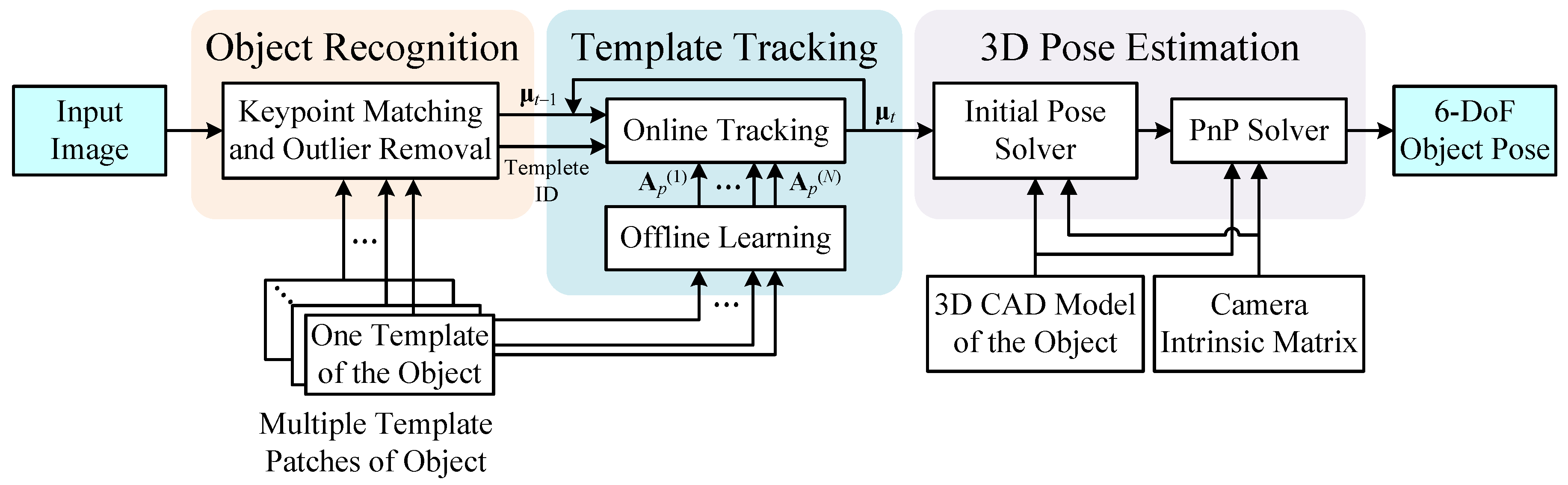
Figure 1 shows the framework of the proposed model-based object pose estimation system, which consists of three modules: object recognition, template tracking and 3D pose estimation. The object recognition module aims to detect and recognize the OOI from the input image using a keypoint-based object detection algorithm. For extracting keypoint descriptors of an image or template patch, the Scale-Invariant Feature Transform (SIFT) algorithm with Graphics Processing Unit (GPU) acceleration [24] was employed to improve the robustness and real-time performance of the proposed system. Moreover, a GPU-accelerated multi-resolution keypoint-descriptor matching algorithm [25] was used to detect the OOI by matching the keypoint descriptors between the input image and the multi-template database.
Given multiple template patches of the OOI, a keypoint-descriptor dataset was created a priori by recording the SIFT descriptors of each template patch of the OOI. When a scene image is captured, the SIFT algorithm is applied to extract the SIFT descriptors of the input image, and the keypoint-descriptor matching algorithm is then used to find the matching points between the scene descriptors and the reference descriptors of the template database. Next, a Random Sample Consensus (RANSAC) algorithm [26] is employed to remove outliers from the keypoint matches, and the template with maximum matching inliers is used to determine the initial position of the OOI in the image using an initial homography estimation method [27].
When the OOI in the image is detected, the corresponding initial homography parameters and template index (ID) number are sent to activate the template tracking module to track the target in the incoming frames. In this work, the existing HA template tracking algorithm [19] was extended to multi-template tracking, and the technical details are presented in the next section. Based on the tracking result, the six degree-of-freedom (6-DoF) pose of the OOI is estimated by the 3D pose estimation module, which is a PnP solver as given in Figure 1 and presented in Section 4.
3. Multi-Template Tracking Algorithm
The template tracking module was designed based on an HA template tracker, which consists of an offline learning and an online tracking process. The former process learns a tracking model of the target based on template patch of the target, and the latter process works with the trained tracking model to predict the optimal position of the OOI between the input image and the reference template in the sense of energy minimization [28]. In this section, a multi-template tracking algorithm is proposed based on the HA template tracking algorithm.
3.1. Offline Learning
Suppose that there are N template patches of the OOI in the database, and each of them is assigned an ID number from 1–N. In each template patch, Ns sample points are selected as the reference intensity pixels denoted by , where the symbol j denotes the ID number of the template, denotes the sample-point set of the j-th template and denotes the image coordinates of the i-th reference intensity pixel (xi,yi) in the j-th sample-point set. We also define an initial parameter vector , which stores n parameters of the j-th position prediction model that predicts the new image coordinates of a pixel location p of the j-th template patch w.r.t. a parameter vector μ.
Let denote the intensity image of the j-th template patch and a motion variation model that predicts a motion variation vector w.r.t. the intensity differences between two consecutive images at some pixel locations X evaluated under a given parameter vector μ. In the offline learning process, the goal is to find the motion variation model for each given template patch. To achieve this goal, a large number of random motion transformations with k = 1~Nt and is generated a priori to form a reference motion variation matrix . Next, a corresponding intensity variation matrix is computed based on the initial parameter vector and the random transformations such that:
which is the k-th intensity-variation vector of the j-th reference intensity template associated with the k-th random transformation. Suppose that the j-th motion variation model is a linear predictor related to the j-th intensity variation vector given by Equation (1). Then, we have Equation (2) as follows:
where is an n-by-Ns matrix to predict the j-th motion variation vector from the j-th intensity variation vector associated with the parameter vector in the sense of the minimal SSD criterion such that:
A closed-form solution to the minimum optimization problem (3) can be solved as:
which is computationally expensive because it requires inverting an Ns-by-Ns matrix . Therefore, the closed-form solution (4) is unsuitable to be used in the online learning of the template tracking module.
3.2. Online Tracking
When the object recognition module had detected the OOI using one template in the database, the corresponding template ID number was stored, and an initial homography matrix was computed to form an a priori parameter vector μt−1 of the position prediction model. Let J denote the stored template ID number. To track the OOI in the current image, denoted by , the corresponding intensity variation vector w.r.t. the reference intensity pixels is given by Equation (5), as follows:
which is used to predict the motion variation δμt between the two consecutive images such that:
Similar to the forward additional and forward compositional algorithms used in dense image alignment [29], the prediction result obtained from Equation (6) is used to update the a priori parameter vector μt−1 of the position prediction model such that:
Finally, the time index is updated by to track the OOI in the next input image continuously.
4. Model-Based 3D Pose Estimation
As suggested in [30], the PnP methods usually work better than the HD methods because it optimizes the pose based on a cost function related to the correspondence mapping errors. Therefore, the proposed 3D pose estimation module includes an initial pose solver and a PnP solver. The former solves the initial 3D pose of the OOI based on an efficient HD algorithm and the latter refines the initial pose result using the PnP algorithm.
4.1. Initial Pose Solver
Suppose that each template patch in the database corresponds to a 3D planar model of the OOI. When working with the template tracking result, the correspondences between 2D image features of the tracked template patch and 3D control points of the CAD model of the object can be determined efficiently. For the j-th 3D planar model, we define Nc coplanar 3D control points on this model for n = 1~Nc and . Let denote the i-th element of the n-th 3D control point, where i = 1~3. If the OOI has been tracked using the j-th template, then we calculate the mean vector of the corresponding 3D control points of the planar model using Equation (8):
where denotes the center location of the j-th 3D planar model. Next, a three-by-three covariance matrix of the 3D control points is calculated using Equation (9)
which can be decomposed by Singular-Value-Decomposition (SVD) such that:
where and are real unitary matrices and is a rectangular diagonal matrix with non-negative singular values on the diagonal. According to the SVD result from Equation (10), the control points of the 3D planar model are transformed by a unitary transformation such that:
As a result, the Z-value of the transformed 3D control point is fixed to zero, or . Let denote 2D feature points corresponding to the projection of the 3D planar control points onto the image plane. Define a mapping function by . Then, an optimal homography matrix Hopt between the transformed 3D planar model and the 2D image plane can be obtained by solving the following nonlinear optimization problem:
where is formed by the result of Equation (11). Suppose that the camera was calibrated previously. By using the camera intrinsic matrix K and Equation (12), the pose matrix of the transformed 3D planar model in the unitary coordinate system can be solved by the perspective HD method [18] such that:
which can be used to recover the rotation matrix of the transformed 3D planar model such that:
where the symbol denotes the two-norm value of the vector x and the operator × represents the cross-product of two vectors. Finally, the initial 6-DoF pose of the 3D planar model in the original camera coordinate system can be estimated according to Equations (13) and (14) such that:
where R0 and T0 represent the initial rotation matrix and the translation vector of the OOI w.r.t. the camera system, respectively.
4.2. PnP Solver
Once the initial pose of the OOI has been obtained, the optimal pose solution can be further estimated based on the correspondences between the 2D feature points and the 3D control points. Let denote a projection function of a 3D point associated with a rotation matrix R and a translation vector T as follows:
where K is the camera intrinsic matrix. Then, the re-projection error between the 2D-3D correspondences can be computed by:
where ρ(X) is the mapping function of a 3D point X defined previously. Hence, the proposed PnP solver aims to refine the initial pose (R0,T0) of the OOI by minimizing the re-projection error of Equation (17) such that:
where Ropt and Topt are the optimal rotation matrix and the optimal translation vector of the OOI w.r.t. the camera system, respectively. The performance of the proposed model-based object pose estimation algorithm is evaluated in the next section.
5. Experimental Results
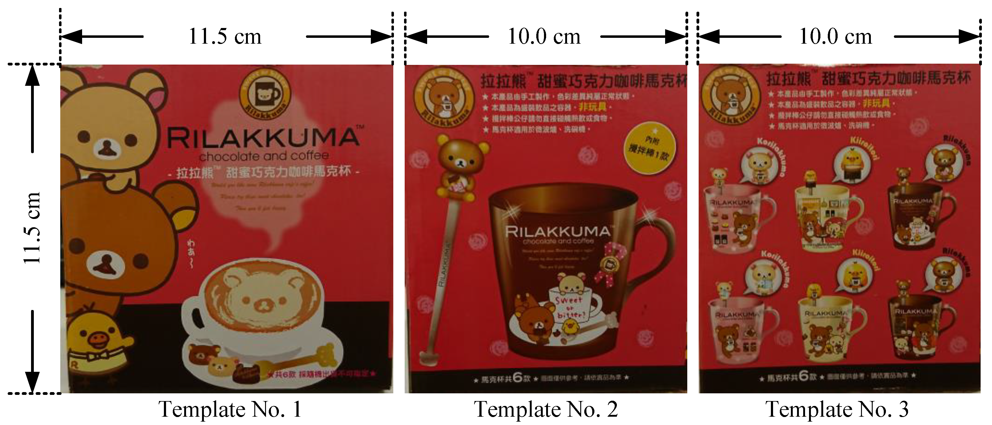
Figure 2 shows three template patches of a cube box used as an OOI in the experiments. For each template patch, the four corners of the image were set as the control points used in the proposed algorithm. The camera used in the experiments was a Logitech HD Pro Webcam C920, which provides images with a size of 1280 × 720 pixels. The camera was calibrated, and its intrinsic matrix is given below:
which is used in Equations (13) and (16). For evaluating the estimation performance of the proposed algorithm, the following experiments focus on four issues, including: (1) pose estimation testing; (2) quantitative evaluation; (3) computational efficiency; and (4) multi-object pose tracking discussed in the proposed algorithm.
5.1. Pose Estimation Results
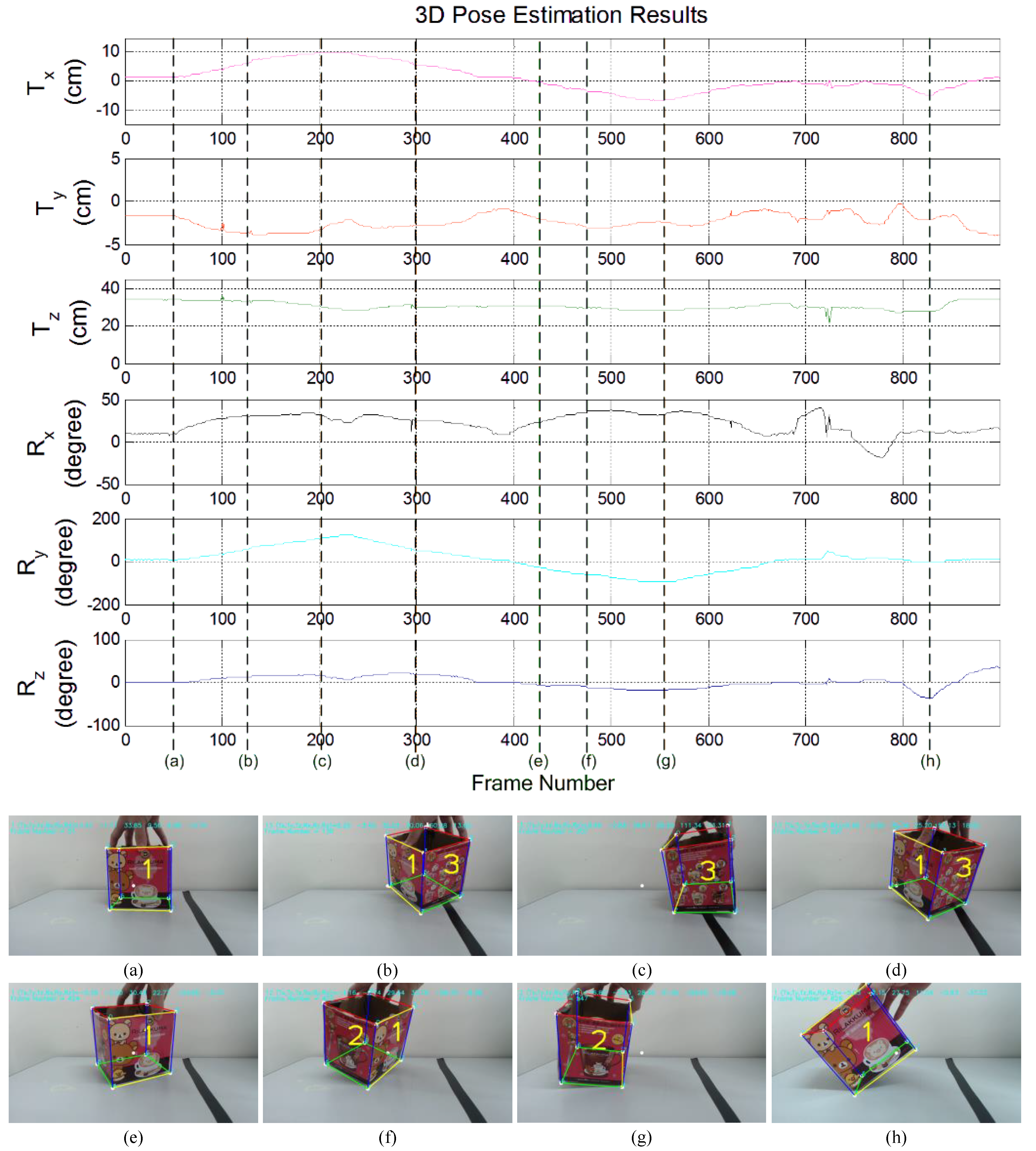
Figure 3 shows the experimental results of the proposed object pose estimation algorithm in tracking the OOI with the three templates shown in Figure 2. In this experiment, the OOI was firstly rotated around the y-axis in a clockwise direction as shown in Figure 3a–c. Hence, the 3D pose of the OOI was estimated by continuously tracking the templates from No. 1–No. 3. Next, the OOI was rotated around the y-axis in a counterclockwise direction as shown in Figure 3d–g. The 3D pose of the OOI was then estimated by tracking the template No. 3, No. 1 and No. 2, successively. Finally, the OOI was rotated back to the initial pose, and it was then rotated around the z-axis in a counterclockwise direction as shown in Figure 3h. From the 3D pose estimation result shown in Figure 3, it is clear that the value of Ry is firstly increased from 0° to about 120° and then is decreased in steps to about −95°. After that, the value of Ry is returned to about 0°, and the value of Rz is then decreased from 0° to about −37°. These pose estimation results are consistent with the actual motion trajectory of the OOI in the experiment. Therefore, the pose estimation performance of the proposed algorithm to deal with an OOI having a multi-plane structure is validated.
5.2. Quantitative Evaluation
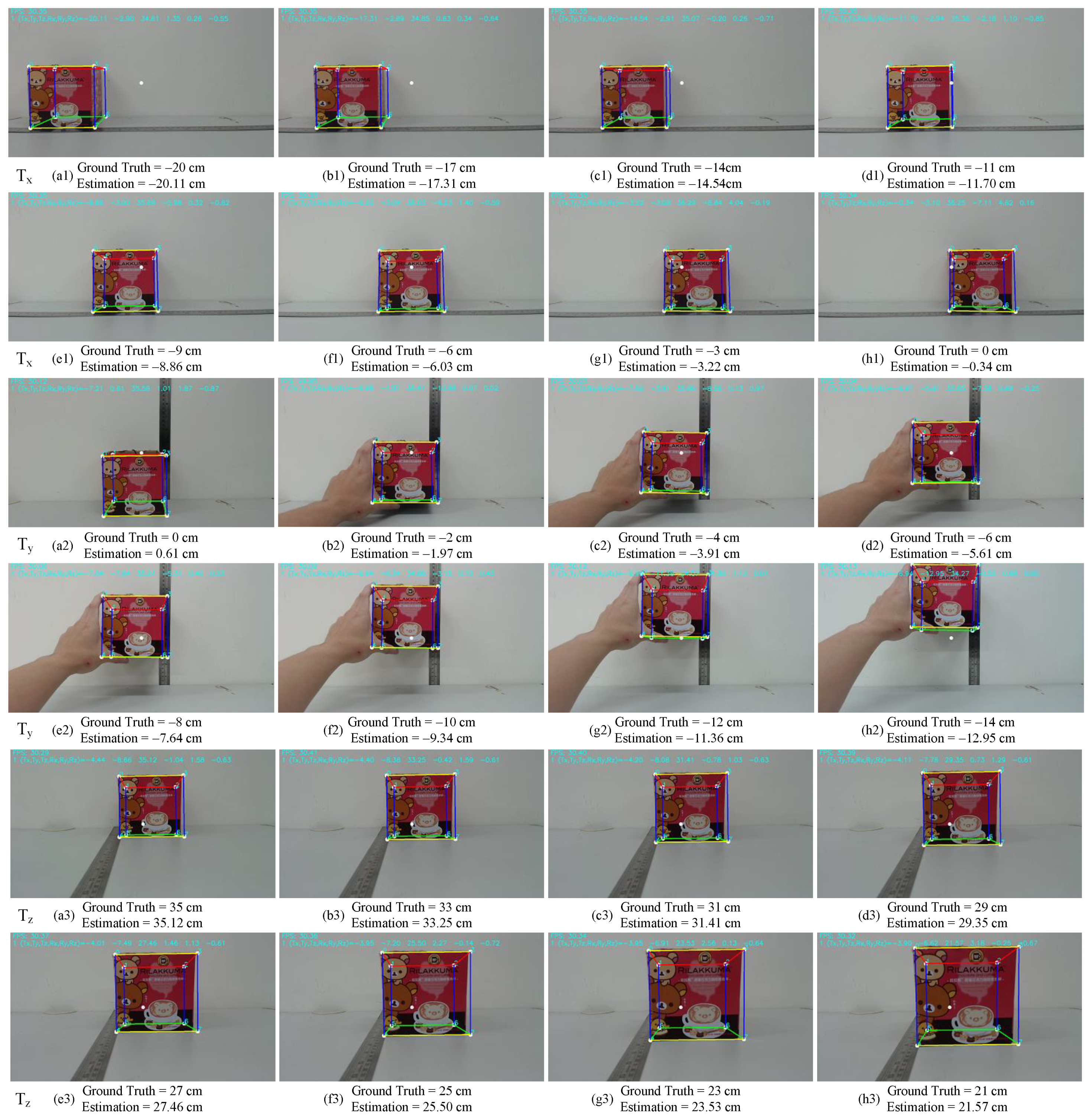
To evaluate the estimation accuracy of the proposed algorithm quantitatively, a protractor and a ruler were used in the experiments to measure the orientation angle and the translation distance of the target along an axis manually, respectively. These measures were used as the ground truth of the target poses. Figure 4 illustrates the translation estimation results of the proposed algorithm. The experimental results of target translations along the x−, y- and z-axes are shown in Figure 4a1–h1, Figure 4a2–h2 and Figure 4a3–h3, respectively. From Figure 4a1–h1, it is clear that the maximum absolute translation error (defined by |Ground Truth–Estimation|) is less than 0.8 cm on the x-axis. In Figure 4a2–h2, the maximum absolute translation error along the y-axis is about 1.0 cm when the target is close to the boundary of the image. In Figure 4a3–h3, the maximum absolute translation error along the z-axis is less than 0.6 cm. Therefore, the accuracy of the target translation estimation of the proposed algorithm is verified.
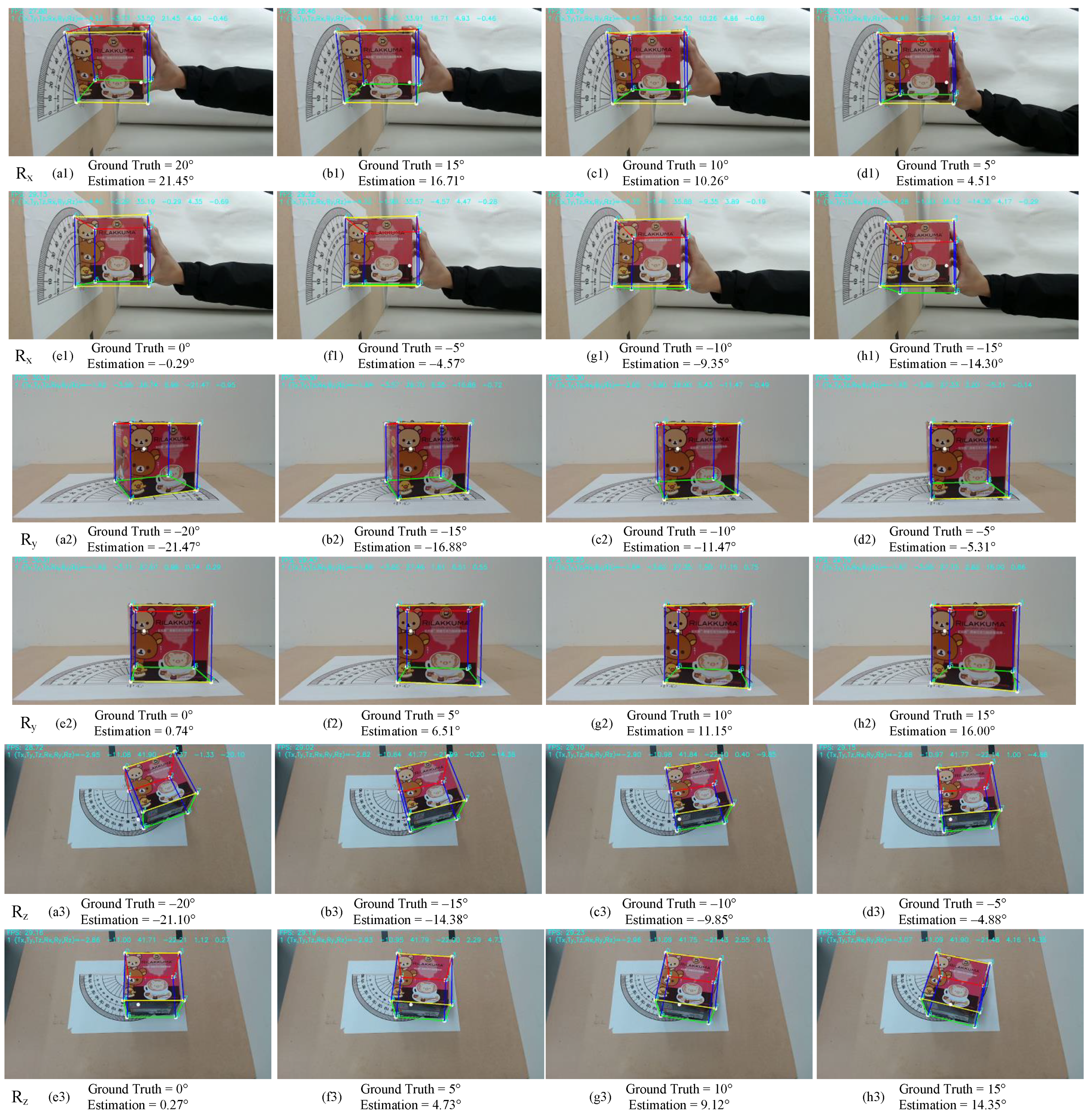
Figure 5 presents the rotation estimation results of the proposed algorithm. Similarly, the experimental results of target rotation estimation in the x-, y-, and z-axes are shown in Figure 5a1–h1, Figure 5a2–5h2 and Figure 5a3–h3, respectively. From Figure 5, the maximum absolute rotation error is less than 1.8 degrees across the x-axis, 1.9 degrees across the y-axis and 0.9 degrees across the z-axis. Hence, the accuracy of the target rotation estimation of the proposed algorithm is also verified.
Based on the above experimental results, two estimation error criteria were employed to quantitatively evaluate the estimation performance of the proposed algorithm as follows:
where Ω = {x,y,z} denotes one of the three axes of the 3D Cartesian coordinate system; RΩ and TΩ denote the ground truths of the rotation angle and translation distance on the Ω-axis, respectively; and denote the corresponding estimates of the rotation angle and translation distance obtained from the proposed algorithm, respectively.
Table 1 records the estimation errors of the experimental results shown in Figure 4 and Figure 5. The last row in Table 1 shows the average estimation error of the experiments. From Table 1, it is clear that the rotation estimation in y-axis has the largest estimation error of about 1.64 degrees on average. By contrast, the average rotation estimation errors in both the x- and z-axis are smaller than 0.82° and 0.23°, respectively.
Moreover, the translation estimation errors in the three axes are all smaller than 0.33 cm on average. In other words, the average percentage error of the translation estimation results is lower than 3.3% when compared to the real dimensions of the object. This result is similar to the extended Kalman filter-based direct homography tracking method [23], which also has a percentage error of 3.3% represented in the translational error. This accuracy level is suitable for many practical applications, such as augmented reality. Therefore, the above quantitative analysis confirms that the proposed model-based object pose estimation algorithm can provide accurate and stable 3D pose estimation results of the OOI having a multi-planar structure.
5.3. Computational Efficiency
The proposed algorithm was implemented in C++ running on a Windows 7 platform equipped with a 3.6-GHz Intel® Core(TM) i7-4790 CPU and an NVIDIA Tesla C2050 GPU, which has 448 CUDA cores [31]. Table 2 tabulates the average processing time in each stage of the proposed model-based object pose estimation algorithm. From Table 2, it is clear that the stage of object recognition costs the most processing time of the proposed algorithm. However, when the OOI has been detected, the stage of the proposed algorithm is switched to template tracking and 3D pose estimation processes, which cost about 1.09 ms on average after tracker initialization. Therefore, the proposed algorithm can achieve extremely high processing speeds when the OOI is detected from the input image.
5.4. Multi-Object Pose Tracking
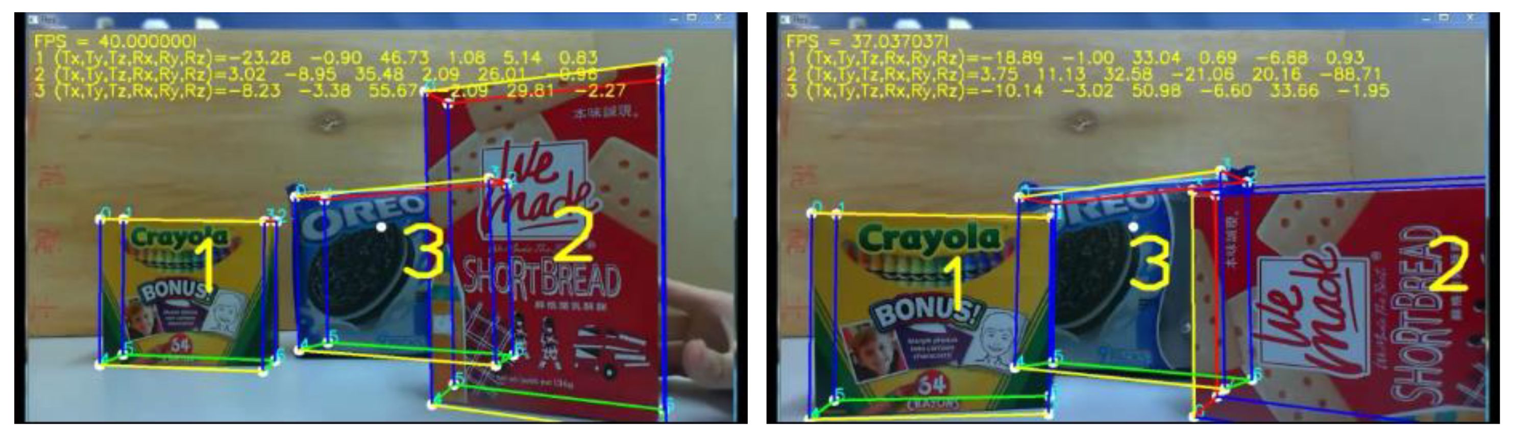
The proposed method can be extended to track multiple objects. Figure 6 shows the experimental results of the proposed method to track three different objects simultaneously. From Figure 6, it is clear that the proposed method not only performs 3D pose tracking of multiple objects with a frame rate higher than 30 frames per second (FPS), but also overcomes the partial occlusion of the object No. 3 in the tracking process. Moreover, the pose estimation results are also accurate when the objects No. 1 and No. 2 change their poses. Therefore, these experimental results validate the tracking performance and tracking accuracy of the proposed pose estimation algorithm. Two video clips of the experiment can be accessed through the webpages of [32,33].
Remark: From the above experimental results, we conclude that the advantage of the proposed method includes the real-time performance in tracking multiple targets and the accuracy of the pose estimation results. However, there are still some limitations of the proposed method; for example, the proposed method is not able to track textureless objects or planar objects with homogeneous surfaces. Furthermore, an unfavorable lighting condition may significantly reduce the tracking performance of the proposed method.
6. Conclusions and Future Work
In this paper, a novel and efficient model-based object pose estimation algorithm is proposed to achieve an accurate and stable pose tracking function for an OOI having a multi-planar structure. This property can help to implement many computer vision applications. Thanks to the GPU acceleration and the template tracking technologies, the proposed algorithm can efficiently and robustly detect and track the target in real time. Based on the template tracking result, the 3D pose of the OOI can be obtained accurately from the proposed model-based pose estimator, which combines an HD-based initial pose solver and a model-based PnP solver. Experimental results show that the maximum estimation error of the proposed algorithm is in the case of estimating the rotation in the y-axis and is about 1.64° on average. Otherwise, the proposed algorithm can provide accurate pose estimation results. The rotation estimation errors in both the x- and z-axis are about 0.81° and 0.22° on average, respectively. The translation estimation errors in the three axes are all smaller than 0.33 cm on average. Moreover, the entire system achieves an extremely high processing speed on a desktop computer equipped with a GPU accelerator. These advantages significantly increase the applicability of the proposed algorithm in practical applications.
In the future, a robust visual tracker can be integrated with the template tracker to improve the tracking robustness of the system to overcome external uncertainties during the pose tracking process. Furthermore, it is also crucial to combine a robust object detection method, such as a deep learning-based object detector [34], with the proposed algorithm to detect the target in complex scenes, which helps to improve the robustness and computational efficiency of the proposed algorithm in practical applications.
Author Contributions
Conceptualization, Tsai, C.Y. and Nisar, H. Methodology, Tsai, C.Y. Software, Tsai, C.Y. and Hsu, K.J. Validation, Tsai, C.Y. and Hsu, K.J. Formal analysis, Tsai, C.Y. Investigation, Tsai, C.Y. Resources, Tsai, C.Y. and Nisar, H. Data curation, Hsu, K.J. Writing, original draft preparation, Tsai, C.Y. Writing, review and editing, Tsai, C.Y. and Nisar, H. Visualization, Tsai, C.Y. Supervision, Tsai, C.Y. Project administration, Tsai, C.Y. Funding acquisition, Tsai, C.Y.
Acknowledgments
This work was supported by the Ministry of Science and Technology of Taiwan, ROC, under Grant MOST 107-2221-E-032-049 and was supported in part by NUWA Robotics Co., Ltd, Nanjing East Road, Zhongshan District, Taipei City 104, Taiwan.
Conflicts of Interest
The authors declare no conflict of interest.
References
- Lowe, D.G. Distinctive image features from scale-invariant keypoints. Int. J. Comput. Vis. 2004, 60, 91–110. [Google Scholar] [CrossRef]
- Bay, H.; Ess, A.; Tuytelaars, T.; Gool, V.L. Speeded-up robust features (SURF). Compu. Vis. Image Underst. 2008, 110, 346–359. [Google Scholar] [CrossRef]
- Calonder, M.; Lepetit, V.; Özuysal, M.; Trzcinski, T.; Strecha, C.; Fua, P. BRIEF: Computing a local binary descriptor very fast. IEEE Trans. Pattern Anal. Mach. Intell. 2012, 34, 1281–1298. [Google Scholar] [CrossRef] [PubMed]
- Rublee, E.; Rabaud, V.; Konolige, K.; Bradski, G. ORB: An efficient alternative to SIFT and SURF. In Proceedings of the IEEE International Conference on Computer Vision, Barcelona, Spain, 6–13 November 2011. [Google Scholar]
- Lepetit, V.; Lagger, P.; Fua, P. Randomized trees for real-time keypoint recognition. In Proceedings of the IEEE International Conference on Computer Vision and Pattern Recognition, San Diego, CA, USA, 20–25 June 2005. [Google Scholar]
- Lepetit, V.; Fua, P. Keypoint recognition using randomized trees. IEEE Trans. Pattern Anal. Mach. Intell. 2006, 28, 1465–1479. [Google Scholar] [CrossRef] [PubMed]
- Decker, P.; Paulus, D. Model based pose estimation using SURF. In Proceedings of the 10th Asian Conference on Computer Vision, Queenstown, New Zealand, 8–12 November 2010. [Google Scholar]
- Choi, C.; Christensen, H.I. Real-time 3D model-based tracking using edge and keypoint features for robotic manipulation. In Proceedings of the IEEE International Conference on Robotics and Automation, Anchorage, AK, USA, 3–7 May 2010. [Google Scholar]
- Harris, C. Tracking with Rigid Objects; MIT Press: Massachusetts, MA, USA, 1992. [Google Scholar]
- Zhang, Y.; Li, X.; Liu, H.; Shang, Y. Probabilistic approach for maximum likelihood estimation of pose using lines. IET Comput. Vis. 2016, 10, 475–482. [Google Scholar] [CrossRef]
- Tsai, C.-Y.; Wang, W.-Y.; Tsai, S.-H. 3D object pose tracking using a novel model-based contour fitting algorithm. ICIC Express Lett. 2016, 10, 563–568. [Google Scholar]
- Tsai, C.-Y.; Tsai, S.-H. Simultaneous 3D object recognition and pose estimation based on RGB-D images. IEEE Access. 2018, 6, 28859–28869. [Google Scholar] [CrossRef]
- Zhang, Z. A flexible new technique for camera calibration. IEEE Trans. Pattern Anal. Mach. Intell. 2000, 22, 1330–1334. [Google Scholar] [CrossRef] [Green Version]
- Sturm, P. Algorithms for plane-based pose estimation. In Proceedings of the IEEE Conference on Computer Vision and Pattern Recognition, Hilton Head Island, SC, USA, 15 June 2000. [Google Scholar] [Green Version]
- Collins, T.; Durou, J.-D.; Gurdjos, P.; Bartoli, A. Single-view perspective shape-from-texture with focal length estimation: A piecewise affine approach. In Proceedings of the 5th International Symposium on 3D Data Processing, Visualization, and Transmission, Paris, France, 17–20 May 2010. [Google Scholar]
- Simon, G.; Fitzgibbon, A.W.; Zisserman, A. Markerless tracking using planar structures in the scene. In Proceedings of the IEEE and ACM International Symposium on Augmented Reality, Munich, Germany, 5–6 October 2000. [Google Scholar]
- Hager, G.D.; Belhumeur, P.N. Efficient region tracking with parametric models of geometry and illumination. IEEE Trans. Pattern Anal. Mach. Intell. 1998, 20, 1025–1039. [Google Scholar] [CrossRef] [Green Version]
- Buenaposada, J.M.; Baumela, L. Real-time tracking and estimation of plane pose. In Proceedings of the IEEE International Conference on Pattern Recognition, Quebec, QC, Canada, 11–15 August 2002. [Google Scholar]
- Jurie, F.; Dhome, M. Hyperplane approximation for template matching. IEEE Trans. Pattern Anal. Mach. Intell. 2002, 24, 996–1000. [Google Scholar] [CrossRef] [Green Version]
- Zheng, Q.; Wang, Y.; Heng, P.A. Online robust image alignment via subspace learning from gradient orientations. In Proceedings of the IEEE International Conference on Computer Vision, Venice, Italy, 22–29 October 2017. [Google Scholar]
- Tjaden, H.; Schwanecke, U.; Schömer, E. Real-time monocular pose estimation of 3D objects using temporally consistent local color histograms. In Proceedings of the IEEE International Conference on Computer Vision, Venice, Italy, 22–29 October 2017. [Google Scholar]
- Chang, C.-H.; Chou, C.-N.; Chang, E.Y. CLKN: Cascaded Lucas-Kanade networks for image alignment. In Proceedings of the IEEE Conference on Computer Vision and Pattern Recognition, Honolulu, HI, USA, 21–26 July 2017. [Google Scholar]
- Ha, H.; Rameau, F.; Kweon, I.S. 6-DOF direct homography tracking with extended Kalman filter. In Proceedings of the 7th Pacific-Rim Symposium, PSIVT 2015, Auckland, New Zealand, 25–27 November 2015; Bräunl, T., McCane, B., Rivera, M., Yu, X., Eds.; Lecture Notes in Computer Science. Volume 9431, pp. 447–460. [Google Scholar]
- A GPU Implementation of David Lowe’s Scale Invariant Feature Transform. Available online: https://github.com/pitzer/SiftGPU (accessed on 11 August 2018).
- Tsai, C.-Y.; Huang, C.-H.; Tsao, A.-H. Graphics processing unit-accelerated multi-resolution exhaustive search algorithm for real-time keypoint descriptor matching in high-dimensional spaces. IET Comput. Vis. 2016, 10, 212–219. [Google Scholar] [CrossRef]
- Fischler, M.A.; Bolles, R.C. Random sample consensus: A paradigm for model fitting with applications to image analysis and automated cartography. Commun. ACM 1981, 24, 381–395. [Google Scholar] [CrossRef]
- Hartley, R.; Zisserman, A. Multiple View Geometry in Computer Vision, 2nd ed.; Cambridge University Press: Cambridge, UK, 2004. [Google Scholar]
- Holzer, S.; Ilic, S.; Tan, D.; Pollefeys, M.; Navab, N. Efficient learning of linear predictors for template tracking. Int. J. Comput. Vis. 2015, 111, 12–28. [Google Scholar] [CrossRef]
- Crivellaro, A.; Fau, P.; Lepetit, V. Dense Methods for Image Alignment with an Application to 3D Tracking. Available online: https://infoscience.epfl.ch/record/197866/files/denseMethods2014.pdf (accessed on 11 August 2018).
- Collins, T.; Bartoli, A. Infinitesimal plane-based pose estimation. Int. J. Comput. Vis. 2014, 109, 252–286. [Google Scholar] [CrossRef]
- NVIDIA’s Tesla C2050 Board Specification. Available online: http://www.nvidia.com/docs/io/43395/tesla_c2050_board_specification.pdf (accessed on 11 August 2018).
- Experimental Result of 3d Pose Tracking of Multiple Objects. Available online: https://www.youtube.com/watch?v=wBEHEQMFer4 (accessed on 11 August 2018).
- Experimental Result of 3d Pose Tracking of a Single Object. Available online: https://www.youtube.com/watch?v=-uVUbBIPAH4 (accessed on 11 August 2018).
- Redmon, J.; Farhadi, A. YOLO9000: Better, faster, stronger. In Proceedings of the IEEE Conference on Computer Vision and Pattern Recognition, Honolulu, HI, USA, 21–26 July 2017. [Google Scholar]
Figure 1.
System framework of the proposed model-based object pose estimation algorithm.

Figure 2.
Three template patches of the Object-Of-Interest (OOI) used in the experiments.

Figure 3.
Pose estimation results of the proposed algorithm in tracking the OOI with the three templates shown in Figure 2: 3D pose estimation by tracking (a) the template No. 1, (b) the two templates No.1 and No. 3, (c) the template No. 3, (d) the two templates No.1 and No. 3 again, (e) the template No. 1, (f) the two templates No. 1 and No. 2, (g) the template No. 2 and (h) the template No. 1 with a rotation on the z-axis.

Figure 4.
Experimental results of the proposed algorithm to estimate the translation motions of the OOI along the (a1–h1) x-axis, (a2–h2) y-axis and (a3–h3) z-axis.
Figure 4.
Experimental results of the proposed algorithm to estimate the translation motions of the OOI along the (a1–h1) x-axis, (a2–h2) y-axis and (a3–h3) z-axis.

Figure 5.
Experimental results of the proposed algorithm to estimate the rotation angles of the (a1–h1) x-axis, (a2–h2) y-axis and (a3–h3) z-axis of the OOI.
Figure 5.
Experimental results of the proposed algorithm to estimate the rotation angles of the (a1–h1) x-axis, (a2–h2) y-axis and (a3–h3) z-axis of the OOI.

Figure 6.
Experimental results of multi-object pose tracking of the proposed algorithm [32].
Figure 6.
Experimental results of multi-object pose tracking of the proposed algorithm [32].


| Estimation Error | ||||||
|---|---|---|---|---|---|---|
| Unit | cm | Degree | ||||
| eTx | eTy | eTz | eRx | eRy | eRz | |
| (a) | 0.0121 | 0.3721 | 0.0144 | 2.1025 | 2.1609 | 0.0100 |
| (b) | 0.0961 | 0.0009 | 0.0625 | 2.9241 | 3.5344 | 0.3844 |
| (c) | 0.2916 | 0.0081 | 0.1681 | 0.0676 | 2.1609 | 0.0225 |
| (d) | 0.4900 | 0.1521 | 0.1225 | 0.2401 | 0.0961 | 0.0144 |
| (e) | 0.0196 | 0.1296 | 0.2116 | 0.0841 | 0.5476 | 0.0729 |
| (f) | 0.0009 | 0.4356 | 0.2500 | 0.1849 | 2.2801 | 0.0729 |
| (g) | 0.0484 | 0.4096 | 0.2809 | 0.4225 | 1.3225 | 0.7744 |
| (h) | 0.1156 | 1.0816 | 0.3249 | 0.4900 | 1.0000 | 0.4225 |
| Average | 0.1343 | 0.3237 | 0.1794 | 0.8145 | 1.6378 | 0.2218 |
Table 2.
Average processing times in each stage of the proposed algorithm.
| Stage | Object Recognition | Template Tracking | 3D Pose Estimation | ||
|---|---|---|---|---|---|
| Process | Keypoint extraction | Keypoint matching | Tracker initialization | Template tracking | Initial Pose Solver and PnP Solver |
| Average Time | 65 ms | 53 ms | 3.85 ms | 0.39 ms | 0.70 ms |
© 2018 by the authors. Licensee MDPI, Basel, Switzerland. This article is an open access article distributed under the terms and conditions of the Creative Commons Attribution (CC BY) license (http://creativecommons.org/licenses/by/4.0/).
Share and Cite
MDPI and ACS Style
Tsai, C.-Y.; Hsu, K.-J.; Nisar, H. Efficient Model-Based Object Pose Estimation Based on Multi-Template Tracking and PnP Algorithms. Algorithms 2018, 11, 122. https://doi.org/10.3390/a11080122
AMA Style
Tsai C-Y, Hsu K-J, Nisar H. Efficient Model-Based Object Pose Estimation Based on Multi-Template Tracking and PnP Algorithms. Algorithms. 2018; 11(8):122. https://doi.org/10.3390/a11080122
Chicago/Turabian StyleTsai, Chi-Yi, Kuang-Jui Hsu, and Humaira Nisar. 2018. "Efficient Model-Based Object Pose Estimation Based on Multi-Template Tracking and PnP Algorithms" Algorithms 11, no. 8: 122. https://doi.org/10.3390/a11080122
Note that from the first issue of 2016, this journal uses article numbers instead of page numbers. See further details here.