
Effects of Tool Tooth Number and Cutting Parameters on Milling Performance for Bamboo–Plastic Composite
by
 ,
,
Meiqi Song
1,2,†, 
Dietrich Buck
3,†,
Yingyue Yu
2,
Xiaohang Du
2,
Xiaolei Guo
4,
Jinxin Wang
4,5 and
Zhaolong Zhu
1,2,* 1
Co-Innovation Center of Efficient Processing and Utilization of Forest Resources, Nanjing Forestry University, Nanjing 210037, China
2
College of Furnishings and Industrial Design, Nanjing Forestry University, Nanjing 210037, China
3
Department of Wood Science and Engineering, Luleå University of Technology, 931 87 Skellefteå, Sweden
4
College of Materials Science and Technology, Nanjing Forestry University, Nanjing 210037, China
5
Department of Computer and Information Sciences, Northumbria University, Newcastle upon Tyne NE1 8ST, UK
*
Author to whom correspondence should be addressed.
†
These authors contributed equally to this work.
Forests 2023, 14(2), 433; https://doi.org/10.3390/f14020433
Submission received: 3 January 2023
/
Revised: 8 February 2023
/
Accepted: 16 February 2023
/
Published: 20 February 2023
(This article belongs to the Section Wood Science and Forest Products)
Abstract
:Cutting force and temperature are critical indicators for improving cutting performance and productivity. This study used an up-milling experiment to ascertain the effect of tool tooth number, cutting speed, and depth on the machinability of bamboo–plastic composite. We focused on the changes in the resultant force and cutting temperature under different milling conditions. A response surface methodology was used to build prediction models for the resultant force and temperature. A verification test was conducted to prove the model’s reliability. The empirical findings suggested that the number of tool teeth had the most significant impacts on both the resultant force and the cutting temperature, followed by the depth of cut and the cutting speed. Moreover, the resultant force and cutting temperature showed increasing trends with decreasing numbers of tool teeth and increasing cut depths. However, cutting speed had a negative relationship with the resultant force and a positive relationship with temperature. We also determined the optimal milling conditions with the lowest force and temperature: four tool teeth, 300 m/min cutting speed, and 0.5 mm depth. This parameter combination can be used in the industrial manufacture of bamboo–plastic composite to improve tool life and manufacturing productivity.
1. Introduction
Bamboo–plastic composite (BPC) is a new engineering material produced from bamboo as a reinforcing component and compounded with a polymer resin matrix [1]. BPC breaks through the limitations of traditional bamboo applications and represents a high-quality and high-value-added method of utilizing bamboo. BPC integrates the advantages of bamboo and plastic materials, such as high wear resistance, green construction and environmental protection, and good chemical and mechanical properties [2,3,4]. BPC is used in many fields, including in construction, packaging, furniture, and decoration [5,6,7]. Milling is widely used to form final products with differing sizes and shapes [8]. During this milling process, a rotating cutter is fed into a workpiece to remove unneeded material [9]. Determination of the cutting properties for the plastic matrix composites has recently become an attractive topic of research in the field of materials processing. Wu et al. [10] explored the changes in cutting force during the spiral milling of wood–plastic composite. They demonstrated that the cutting force correlated positively with the spindle speed, helical angle, and depth of cut. Pei et al. investigated cutting temperature in related wood–plastic composite research [11]. They showed that the depth of the cut had the greatest effect on the cutting temperature, followed by the spindle speed and the width of milling. Furthermore, Cao et al. [12] and Zhang et al. [13] discussed the cutting force and temperature for stone–plastic composite. They found that the cutting force and temperature showed similar trends with different parameters. Specifically, the cutting force and temperature increased as the rake angle and cutting depth decreased and as cutting speed increased.
To date, research on BPC has mainly focused on its modification and preparation [14,15,16,17,18]. As far as the authors know, there has been no research on cutting performance in relation to BPC, especially cutting force and temperature. Cutting force and temperature are essential performance evaluation indexes in the BPC machining process. They directly or indirectly affect the machining process, including the energy efficiency of machine tools, tool life, and product quality. Due to the lack of systematic research on BPC, workers still use the traditional cutting parameters for bamboo in industrial production of BPC. However, the difference between BPC and bamboo material means that the traditional cutting parameters cannot meet modern processing requirements. This leads to many machining problems, such as severe tool wear, poor quality, and low productivity. Therefore, developing better cutting performance is crucial to improving BPC production quality and cost.
The objective of this study was to enhance cutting performance in the production of BPC. We determined the changes in cutting force and temperature under different conditions, including the number of tool teeth, the cutting speed, and the depth of the cut. We also determined the optimal cutting combination to provide a baseline and scientific guidance for the industrial production of BPC.
2. Materials and Methods
2.1. Workpiece and Cutting Tool
Commercial BPC was used for the workpieces. It was made from 100 parts per hundreds of rubber (phr) bamboo fibre, 100 phr polypropylene, and 3 phr additives (Yayang Composite Material Technology Co., Ltd., Suzhou, China). The BPC workpieces had a length of 180 mm, width of 80 mm, and thickness of 8 mm. The workpiece properties are given in Table 1.
2.2. Measurement Equipment
Figure 1 shows how up-milling was conducted under dry machining conditions in a high-speed machining centre (MGK01, Nanxing Machinery Co., Ltd., Guangdong, China). The dynamic cutting temperature was detected using an A20M infrared imaging camera (Figure 1b; Thermo Fisher Scientific Inc., Waltham, MA, USA). The maximum temperature of the cutting zone was obtained with the software ThermaCAM Researcher Pro 2.10 (Thermo Fisher Scientific Inc., Waltham, MA, USA). Furthermore, the dynamic cutting forces in different directions were recorded with a 9257B high precision dynamometer (Figure 1c; Kistler Group, Winterthur, Switzerland) at a sampling rate of 7300 Hz. The resultant force was defined using Equation (1) [19].
where FR stands for the resultant force in Newtons (N), and Fx, and Fy denote the component forces parallel and perpendicular to the feeding direction in N, respectively.
2.3. Measurement Design
This study focused on cutting variables, including the number of cutting tool teeth, cutting speed, and depth. The values for these variables were selected based on related WPC reports and the manufacturer’s guidance (Table 3). The radial depth of the cut was kept constant at 8 mm. As displayed in Table 4, we used a response surface methodology (RSM) experimental design [20,21,22] and Design-Expert Version 12 (Stat-Ease, Inc., Minneapolis, MN, USA). The functional relationship between the cutting variables and the response of the resultant force or cutting temperature is shown in Equation (2) [23].
where Y is the response of the resultant force or cutting temperature; β0 is the constant term; βi and βij are coefficients of the linear and quadratic terms; βii is the interacting term; and Xi and Xj denote the cutting variables [24].
3. Results and Discussion
3.1. Cutting Resultant Force and Temperature Models
The regression models for the resultant force (FR) and cutting temperature (T) are given in Equations (3) and (4).
where Fr denotes the resultant force in N, T represents the cutting temperature in °C, z stands for the number of teeth, vc is the cutting speed in m/min, and ap is the depth of the cut in mm.
Table 5 lists the resultant force and cutting temperature models’ accuracy evaluation indexes. It shows the standard deviation (Std. Dev.), coefficient of variation (C.V.%), adequate (adeq) precision, R-squared (R2), and adjusted R-squared (Adj-R2) values for these two models. The Std. Dev. and C.V.% represent the degree of dispersion, which was relatively low, thereby suggesting that both models were strongly representative of the results [25]. The adeq precision represented the signal-to-noise ratio. Since the signal-to-noise ratios for both models were higher than 4, as suggested by [26], both models could be adapted to navigate the design space. Furthermore, the R2 and Adj-R2 values for both models were close to 1, indicating that the models had high accuracy [27]. Figure 2 shows that the predicted points for the resultant force and cutting temperature were near the actual points, and no abnormal points were observed [28]. This meant that the proposed models fit the actual data well and could be used to predict the resultant force and cutting temperature to optimize milling parameters.
3.2. Analysis of Variance for Resultant Force and Cutting Temperature
Figure 3 shows that the resulting force and cutting temperature residuals had normal distributions. However, analysis of variance (ANOVA) was used to further check the statistical normality of the data residuals. Table 6 shows the results of the ANOVA for the resultant force with a 0.05 significance level. If the p-value is lower than 0.05, there is a significant effect; otherwise, it is insignificant [29]. The findings suggest that the model was statistically fit for the data (F-value = 17.91; p < 0.05). There is a 0.05% chance that an F-value this large could occur due to noise. Moreover, the ANOVA findings suggested that z, ap, and z2 had statistically significant effects on the resultant force (p < 0.05). However, vc, z × vc, z × ap, vc × ap, vc2, and ap2 had insignificant impacts on the resultant force, as their p-values were greater than the 0.05 significance level. Furthermore, the percentage contribution (% Cont.) is the ratio of the source and the total sum of squares. It indicates the degree of effect on the resultant force; that is, the higher the % Cont. value, the higher the factor’s contribution to the resultant force. The % Cont. value for the tool tooth number (z; % Cont. = 71.61%) was higher than those for the depth of cut (ap; % Cont. = 9.42%) and cutting speed (vc; % Cont. = 0.51%). Thus, it can be concluded that tool tooth number had the most significant influence on the resultant force, followed by the depth of cut and cutting speed.
Furthermore, Table 7 displays the findings of the ANOVA for cutting temperature with a 0.05 significance level. The results suggested that the model was statistically fit for the data (F-value = 105.74; p < 0.05). Moreover, the ANOVA findings suggested that z, vc, ap, and z × ap had statistically significant effects on the cutting temperature (p < 0.05). However, z × vc and vc × ap had insignificant effects on the cutting temperature. The % Cont. value for the tool tooth number (z; % Cont. = 89.85%) was higher than those for the depth of cut (ap; % Cont. = 6.09%) and cutting speed (vc; % Cont. = 0.002%). Thus, it can be concluded that, similarly to the findings for the resultant force, the tool tooth number had the greatest effect on the cutting temperature, followed by the depth of cut and cutting speed.
3.3. Changes in Resultant Force and Cutting Temperature under Different Milling Conditions
Figure 4a–c show the effects of the number of tool teeth, the cutting speed, and the depth of the cut on the resultant force. It should be noted that the resultant force (1) increased with decreasing numbers of teeth and decreasing cutting speed and (2) decreased with decreasing cutting depths. Another key parameter, cutting quantity, affects the magnitudes of the cutting forces and mainly depends on the feed per tooth and average cutting thickness (Figure 5), which are expressed with Equations (5) and (6) [30], respectively:
where Uz is the feed per tooth in mm, D is the tool diameter (8 mm), U is the feed speed (10 m/min), h is the depth of milling in mm, vc is the cutting speed in m/min, and Z denotes the number of tool teeth. (1) At a constant 250 m/min cutting speed and 1.0 mm cutting depth, the number of tool teeth decreased from four to two, the feed per tooth increased from 0.25 mm to 0.50 mm, and the average cutting thickness increased from 0.089 mm to 0.178 mm. (2) At a constant 1.0 mm cutting depth and with three tool teeth, the cutting speed decreased from 300 m/min to 200 m/min, the feed per tooth increased from 0.28 mm to 0.42 mm, and the average cutting thickness increased from 0.099 mm to 0.148 mm. (3) With a constant number of tool teeth of three and 250 m/min cutting speed, the depth of the cut increased from 0.5 mm to 1.5 mm, the feed per tooth remain unchanged at 0.33 mm, and the average cutting thickness increased from 0.084 mm to 0.145 mm. Overall, with decreases in the number of teeth and the cutting speed, the feed per tooth and average cutting thickness increased; i.e., the cutting quantity increased. Thus, a higher resultant force was generated to remove the unneeded material. Moreover, an increased cutting depth improved the cutting quantity in terms of higher average cutting thickness, thereby leading to a stronger cutting force.
Figure 4d–f show the changes in cutting temperature. It can be seen that the cutting temperature was negatively related to the number of teeth, cutting speed, and depth of milling. Based on previous studies [10,11], the generation of heat during the cutting process is mainly determined by (1) the friction between the tool and workpiece and (2) the deformation rate for the removed material. As stated earlier, a decrease in the number of tool teeth and an increase in the depth of the cut resulted in the removal of a greater amount of unneeded material. This led to greater resistance between the tool and workpiece and an increase in cutting temperature. Furthermore, the increase in the cutting speed increased the friction frequency on the interfaces of the flank face-machined surface and the rake face-chip, thereby resulting in greater cutting heat. In general, the cutting temperature was positively related to the cutting speed and depth and negatively correlated with the number of tool teeth.
The two-level interactions affecting the resultant force and temperature are displayed in Figure 6 and Figure 7, respectively. The density of the contour map indicates that the resultant force was mainly affected by the number of tool teeth in the interaction between the number of tool teeth and the cutting speed (Figure 6a) and in the interaction between the number of tool teeth and the depth of the cut (Figure 6b). In the interaction between the depth of the cut and the cutting speed, the resultant force was mainly affected by the depth of the cut (Figure 6c). The cutting temperature was mainly affected by the number of tool teeth in the interaction between the number of tool teeth and the cutting speed (Figure 7a) and in the interaction between number of tool teeth and the depth of the cut (Figure 7b). In the interaction between the depth of the cut and the cutting speed, the cutting temperature was mainly affected by the depth of milling (Figure 7c).
3.4. Optimization and Verification of Milling Conditions
In industrial manufacturing, blunt tools cause abnormal damage to the machined surface, which greatly affects product quality. This requires the workers to stop the machine and change the tool to continue production. Thus, tool wear is an important factor affecting productivity, surface quality, and machining cost [31,32]. According to one study [33], tool wear mainly depends on the generation of force and temperature during cutting processes. Higher cutting force and temperature accelerate tool wear, especially abnormal wear, such as tipping, cracking, and flaking [33]. Therefore, this work adopted the resultant force and temperature as the optimization targets; i.e., the combination of cutting conditions was optimized to obtain the lowest resultant force and temperature possible.
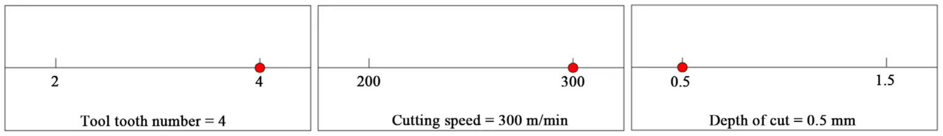
In accordance with the models established by Equations (3) and (4), the optimal cutting conditions for the production of the lowest resultant force and cutting temperature were assumed to be four tool teeth, a cutting speed of 300 m/min, and a cutting depth of 0.5 mm (Figure 8). With this combination of cutting conditions, the predicted resultant force and temperature were 95.9 N and 35.0 °C. To verify the feasibility of the optimal milling conditions, a verification test was conducted (Table 8). With these optimized cutting conditions, the measured resultant force and cutting temperature were 88.6 N and 33.1 °C, with error rates in a reasonable range: −7.6% and −5.4%, respectively. Thus, it can be concluded that the developed models of the resultant force and temperature were reliable. The best milling conditions—namely, those that resulted in the lowest force and temperature—were, therefore, determined to be four tool teeth, a cutting speed of 300 m/min, and a cutting depth of 0.5 mm.
4. Conclusions
In this study, a series of milling experiments were conducted. The influences of the number of tool teeth and the cutting parameters on the milling performance in the production of BPC were discussed, and the main conclusions are as follows:
- With increases in the number of tool teeth and the depth of the cut, both the resultant force and the cutting temperature showed increasing trends. Increased cutting speed led to a lower resultant force and higher cutting temperature;
- Predicted models for the resultant force and cutting temperature were obtained and verified, and the significance of each of the terms in the two models was analysed using ANOVA. Among the three cutting variables, the number of tool teeth had the greatest impact on both the resultant force and cutting temperature, followed by the depth of the cut and the cutting speed;
- Based on the developed models, milling conditions were optimized to produce the lowest force and temperature: four tool teeth, a cutting speed of 300 m/min, and a cutting depth of 0.5 mm;
- This work focused on the changes in cutting force and temperature in the milling of BPC. However, cutting quality, tool wear, and cutting energy consumption are also important evaluation indicators for cutting performance, and they affect both product quality and machining costs. Thus, future research is needed to examine cutting quality, tool wear, and cutting energy consumption under different cutting conditions.
Author Contributions
Conceptualization, Z.Z., M.S., D.B., and X.G.; methodology, X.G., Z.Z., and D.B.; software, X.G.; validation, Z.Z., M.S., D.B., and X.G.; formal analysis, X.D.; investigation, X.D. and Z.Z.; resources, M.S. and Z.Z.; data curation, M.S.; writing—original draft preparation, M.S., Y.Y., and J.W.; writing—review and editing, D.B. and J.W.; visualization, D.B.; supervision, X.G. and Z.Z.; project administration, X.G.; funding acquisition, Z.Z. All authors have read and agreed to the published version of the manuscript.
Funding
This research was supported by the National Natural Science Foundation of China (grant number 31971594), the Natural Science Foundation of the Jiangsu Higher Education Institutions of China (21KJB220009), the Self-Made Experimental and Teaching Instruments of Nanjing Forestry University in 2021 (nlzzyq202101), the project from the Technology Innovation Alliance of Wood/Bamboo Industry (TIAWBI2021-08), Qing Lan Project, and the International Cooperation Joint Laboratory for Production, Education, Research and Application of Ecological Health Care on Home Furnishing.
Data Availability Statement
Not applicable.
Acknowledgments
The authors gratefully acknowledge the considerable support from the CT WOOD at Luleå University of Technology.
Conflicts of Interest
The authors declare no conflict of interest.
References
- Zhu, S.; Guo, Y.; Chen, Y.; Su, N.; Zhang, K.; Liu, S. Effects of the incorporation of nano-bamboo charcoal on the mechanical properties and thermal behavior of bamboo-plastic composites. BioResources 2016, 11, 2684–2697. [Google Scholar] [CrossRef] [Green Version]
- Hu, F.; Li, L.; Wu, Z.; Yu, L.; Liu, B.; Cao, Y.; Xu, H. Surface characteristics of thermally modified bamboo fibers and its utilization potential for bamboo plastic composites. Materials 2022, 15, 4481. [Google Scholar] [CrossRef] [PubMed]
- Jin, X.; Li, J.; Zhang, R.; Jiang, Z.; Qin, D. Fabrication of high-performance bamboo–plastic composites reinforced by natural halloysite nanotubes. Molecules 2020, 25, 2259. [Google Scholar] [CrossRef] [PubMed]
- Jiang, S.; Wei, Y.; Hu, Z.; Ge, S.; Peng, W. Potential application of bamboo powder in PBS bamboo plastic composites. J. King Saud Univ. Sci. 2019, 32, 1130–1134. [Google Scholar] [CrossRef]
- Xian, Y.; Wang, C.; Wang, G.; Smith, L.; Cheng, H.T. Fractal dimension analysis of interface and impact strength in core–shell structural bamboo plastic composites. Iran. Polym. J. 2017, 26, 169–178. [Google Scholar] [CrossRef]
- Xian, Y.; Ma, D.; Wang, C.; Wang, G.; Smith, L.; Cheng, H. Characterization and research on mechanical properties of bamboo plastic composites. Polymers 2018, 10, 814. [Google Scholar] [CrossRef] [Green Version]
- Taghiyari, H.R.; Bari, E.; Sistani, A.; Najafian, M.; Ghanbary, M.A.T.; Ohno, K.M. Biological resistance of nanoclay-treated plastic composites with different bamboo contents to three types of fungi. J. Thermoplast. Compos. Mater. 2019, 33, 1048–1060. [Google Scholar] [CrossRef]
- Cai, G.; Wang, J.; Nie, Y.; Tian, X.; Zhu, X.; Zhou, X. Effects of toughening agents on the behaviors of bamboo plastic composites. Polym. Compos. 2011, 32, 1945–1952. [Google Scholar] [CrossRef]
- Zhang, Q.; Ning, L.; Shen, Y.; Wang, M.; Yan, Y. Study on shielding effectiveness, electrical conductivity and thermal property of bamboo-plastic shielding composite based on Ni-Fe-P coated bamboo fibers. Mater. Lett. 2020, 268, 127578. [Google Scholar] [CrossRef]
- Wu, Z.; Zhang, F.; Hu, Y.; Zhu, Z.; Guo, X. Study on helical milling performance of wood-plastic composites. CIRP J. Manuf. Sci. Technol. 2022, 37, 143–154. [Google Scholar] [CrossRef]
- Pei, Z.J.; Zhu, N.F.; Gong, A. Study on cutting temperature for wood-plastic composite. J. Thermoplast. Compos. 2016, 29, 1627–1640. [Google Scholar] [CrossRef]
- Cao, P.; Zhu, Z.; Buck, D.; Guo, X.; Ekevad, M.; Wang, X.A. Effect of rake angle on cutting performance during machining of stone-plastic composite material with polycrystalline diamond cutters. J. Mech. Sci. Technol. 2019, 33, 351–356. [Google Scholar] [CrossRef]
- Zhang, F.; Wu, Z.; Ding, J.; Guo, X.; Cao, P.; Zhu, Z. Milling performance of stone-plastic composite with diamond cutters. Mater. Werkst. 2021, 52, 1307–1318. [Google Scholar] [CrossRef]
- Xian, Y.; Li, H.; Wang, C.; Wang, G.; Ren, W.; Cheng, H. Effect of white mud as a second filler on the mechanical and thermal properties of bamboo residue fiber/polyethylene composites. BioResources 2015, 10, 4263–4276. [Google Scholar] [CrossRef]
- Song, W.; Zhao, F.; Yu, X.; Wang, C.; Wei, W.; Zhang, S. Interfacial characterization and optimal preparation of novel bamboo plastic composite engineering materials. BioResources 2015, 10, 5049–5070. [Google Scholar] [CrossRef] [Green Version]
- Chen, Q.; Zhang, R.; Qin, D.; Feng, Z.; Wang, Y. Modification of the physical-mechanical properties of bamboo-plastic composites with bamboo charcoal after hydrothermal aging. BioResources 2018, 13, 1661–1677. [Google Scholar] [CrossRef]
- Song, W.; Zhang, S.; Fei, B.; Zhao, R. Mussel-inspired polydopamine modification of bamboo flour for superior interfacial compatibility of bamboo plastic composites: Influence of oxidant type. Cellulose 2021, 28, 8567–8580. [Google Scholar] [CrossRef]
- Xian, Y.; Wang, C.; Wang, G.; Ren, W.; Cheng, H. Understanding the mechanical and interfacial properties of core-shell structured bamboo-plastic composites. J. Appl. Polym. Sci. 2016, 133, 430053. [Google Scholar] [CrossRef]
- Jiang, S.; Buck, D.; Tang, Q.; Guan, J.; Wu, Z.; Guo, X.; Zhu, Z.; Wang, X. Cutting force and surface roughness during straight-tooth milling of walnut wood. Forests 2022, 13, 2126. [Google Scholar] [CrossRef]
- Li, R.; Yang, F.; Wang, X. Modeling and predicting the machined surface roughness and milling power in scot’s pine helical milling process. Machines 2022, 10, 331. [Google Scholar] [CrossRef]
- Fang, L.; Lu, X.; Mo, X.; Zhang, X.; Gui, C. Performance of impregnated paper decorated blockboard manufactured using HDF as equilibrium layer. Materials 2022, 15, 6342. [Google Scholar] [CrossRef] [PubMed]
- Li, R.; Yao, Q.; Xu, W.; Li, J.; Wang, X. Study of cutting power and power efficiency during straight-tooth cylindrical milling process of particle boards. Materials 2022, 15, 879. [Google Scholar] [CrossRef] [PubMed]
- Mishra, S.; Sharma, A.; Kumari, A. Response surface methodology based optimization of air-film blade cooled gas turbine cycle for thermal performance prediction. Appl. Therm. Eng. 2020, 164, 114425. [Google Scholar] [CrossRef]
- Li, R.; He, C.; Wang, X. Effects of processing parameters on mass loss and coating properties of poplar plywood during CO2 laser modification. Eur. J. Wood Wood Prod. 2022, 80, 899–906. [Google Scholar] [CrossRef]
- Hu, W.; Liu, Y.; Konukcu, A.C. Study on withdrawal load resistance of screw in wood-based materials: Experimental and numerical. Wood Mater. Sci. Eng. 2022. [Google Scholar] [CrossRef]
- Hu, W.; Zhang, J. Study on static lateral load–slip behavior of single-shear stapled connections in plywood for upholstered furniture frame construction. J. Wood Sci. 2021, 67, 1–11. [Google Scholar] [CrossRef]
- Li, R.; He, C.; Wang, X. Evaluation and modeling of processability of laser removal technique for bamboo outer layer. JOM J. Miner. Met. Mater. Soc. 2021, 73, 2423–2430. [Google Scholar] [CrossRef]
- Wang, C.; Li, R.; Liu, C.; Wang, X.A. Effects of medium-low temperature hydrothermal treatment on microstructure and dimensional stability of chinese sweetgum wood. Wood Res. 2019, 64, 97–104. [Google Scholar]
- Li, R.; He, C.; Xu, W.; Wang, X. Modeling and optimizing the specific cutting energy of medium density fiberboard during the helical up-milling process. Wood Mater. Sci. Eng. 2022. [Google Scholar] [CrossRef]
- Zhu, Z.L.; Guo, X.L.; Ekevad, M.; Cao, P.X.; Zhu, N.F. The effects of cutting parameters and tool geometry on cutting forces and tool wear in milling high-density fiberboard with ceramic cutting tools. Int. J. Adv. Manuf. Tech. 2017, 91, 4033–4041. [Google Scholar] [CrossRef]
- Guo, X.L.; Deng, M.S.; Wang, J.X.; Zhu, Z.L. Effects of geometric angle and cutting speed on cutting forces and tool wear of ceramic cutting tools during peripheral up-milling of high-density fiberboard. Mater. Werkst. 2020, 51, 461–468. [Google Scholar] [CrossRef]
- Szwajka, K.; Trzepieciński, T. Effect of tool material on tool wear and delamination during machining of particleboard. J. Wood Sci. 2016, 62, 305–315. [Google Scholar] [CrossRef]
- Wei, H.; Guo, X.; Zhu, Z.; Cao, P.; Wang, B.; Ekevad, M. Analysis of cutting performance in high density fiberboard milling by ceramic cutting tools. Wood Res. 2018, 63, 455–466. [Google Scholar]
Figure 1.
Milling experiment: (a) cutting tool, (b) cutting temperature measurement, (c) cutting force measurement.
Figure 1.
Milling experiment: (a) cutting tool, (b) cutting temperature measurement, (c) cutting force measurement.

Figure 2.
(a) Actual and predicted values for resultant force; (b) Actual and predicted values for cutting temperature.
Figure 2.
(a) Actual and predicted values for resultant force; (b) Actual and predicted values for cutting temperature.

Figure 3.
(a) Normal distributions of resultant force; (b) Normal distributions of cutting temperature.
Figure 3.
(a) Normal distributions of resultant force; (b) Normal distributions of cutting temperature.

Figure 4.
Effects of tool tooth numbers and cutting parameters on (a–c) resultant force and (d–f) temperature.
Figure 4.
Effects of tool tooth numbers and cutting parameters on (a–c) resultant force and (d–f) temperature.
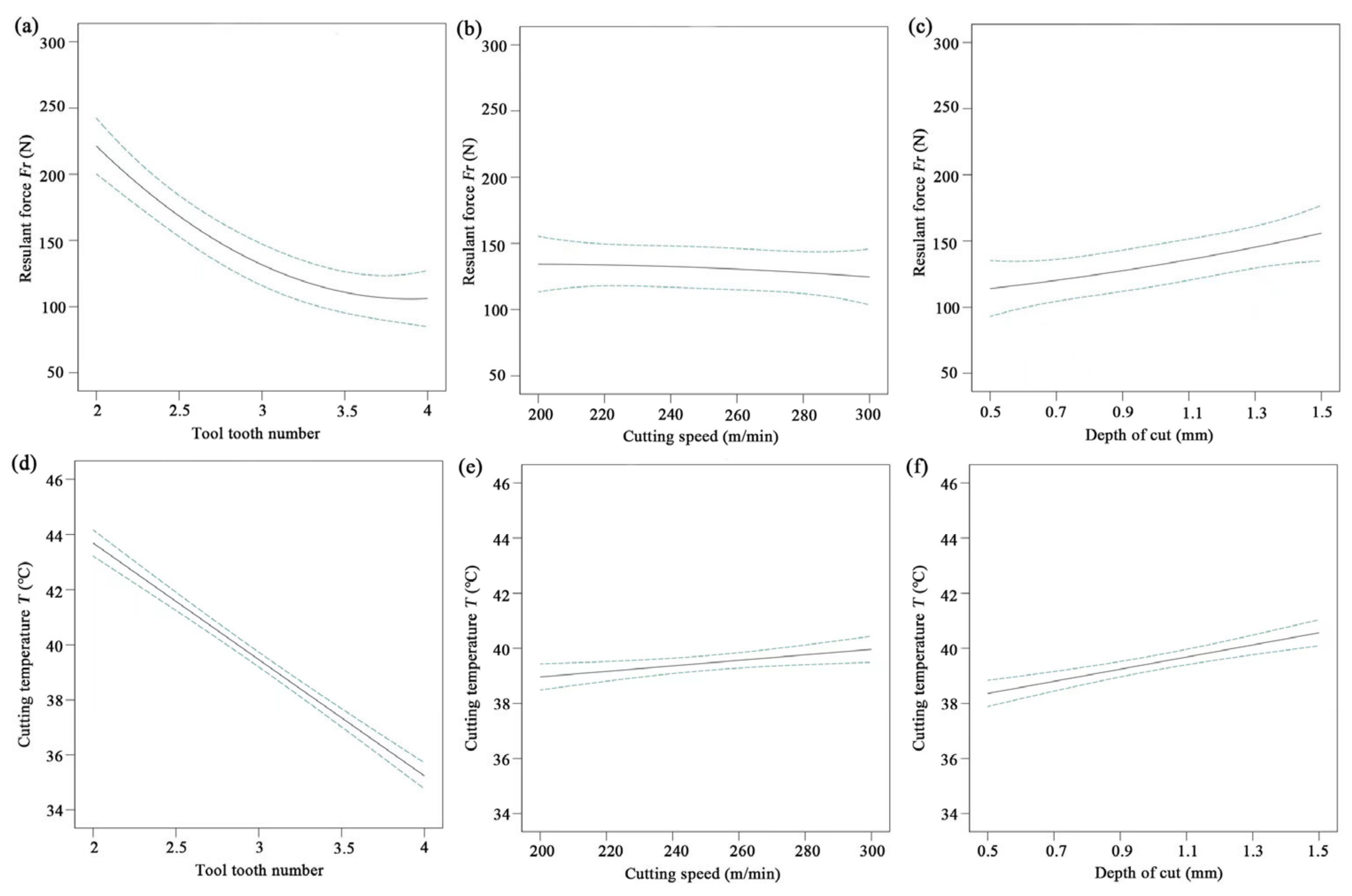
Figure 5.
Changes in cutting quantities under different conditions.
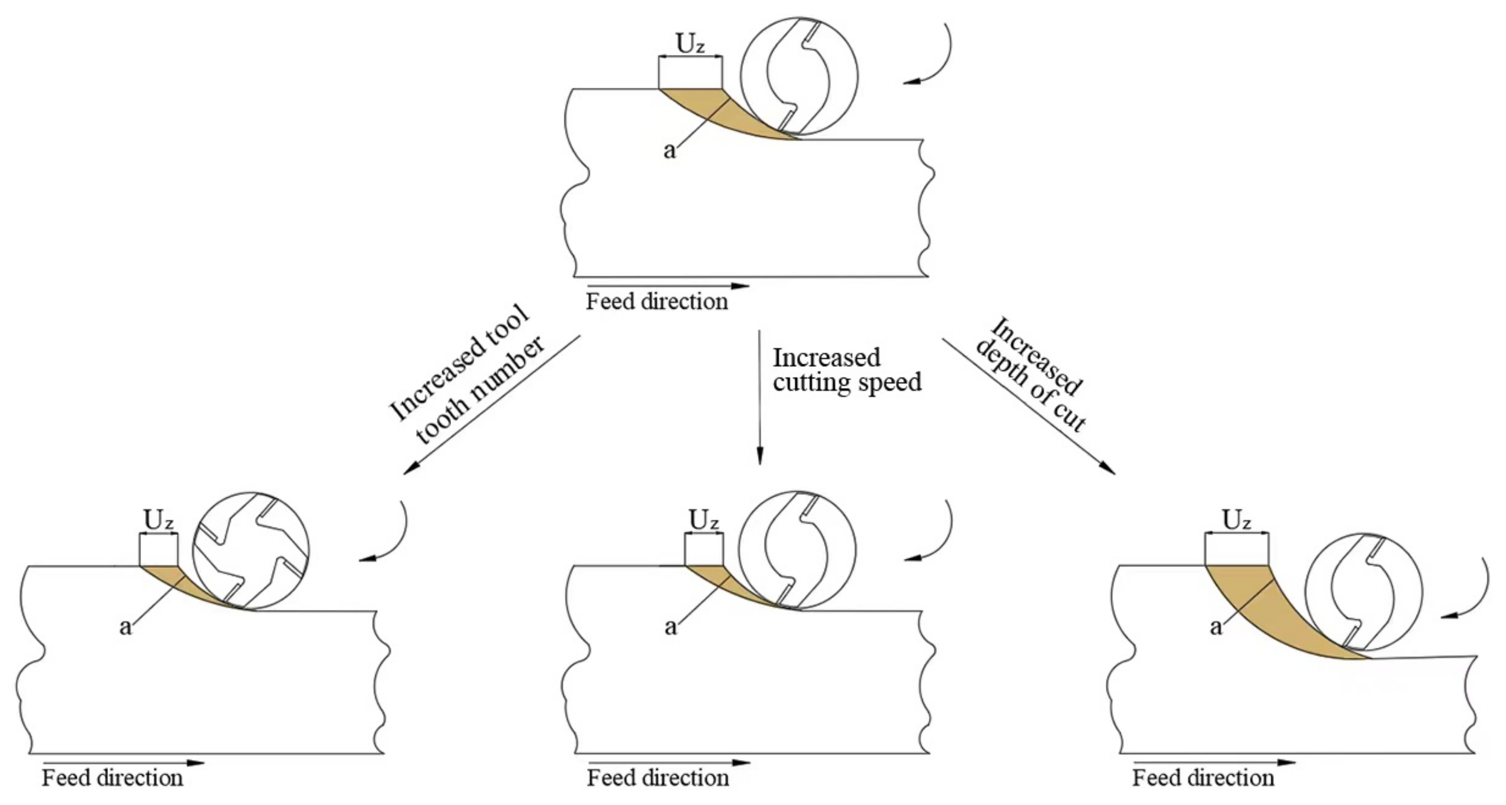
Figure 6.
Three-dimensional surface and contour maps of resultant force (a) tool tooth number and cutting speed, (b) tool tooth number and depth of cut, and (c) cutting speed and depth of cut.
Figure 6.
Three-dimensional surface and contour maps of resultant force (a) tool tooth number and cutting speed, (b) tool tooth number and depth of cut, and (c) cutting speed and depth of cut.
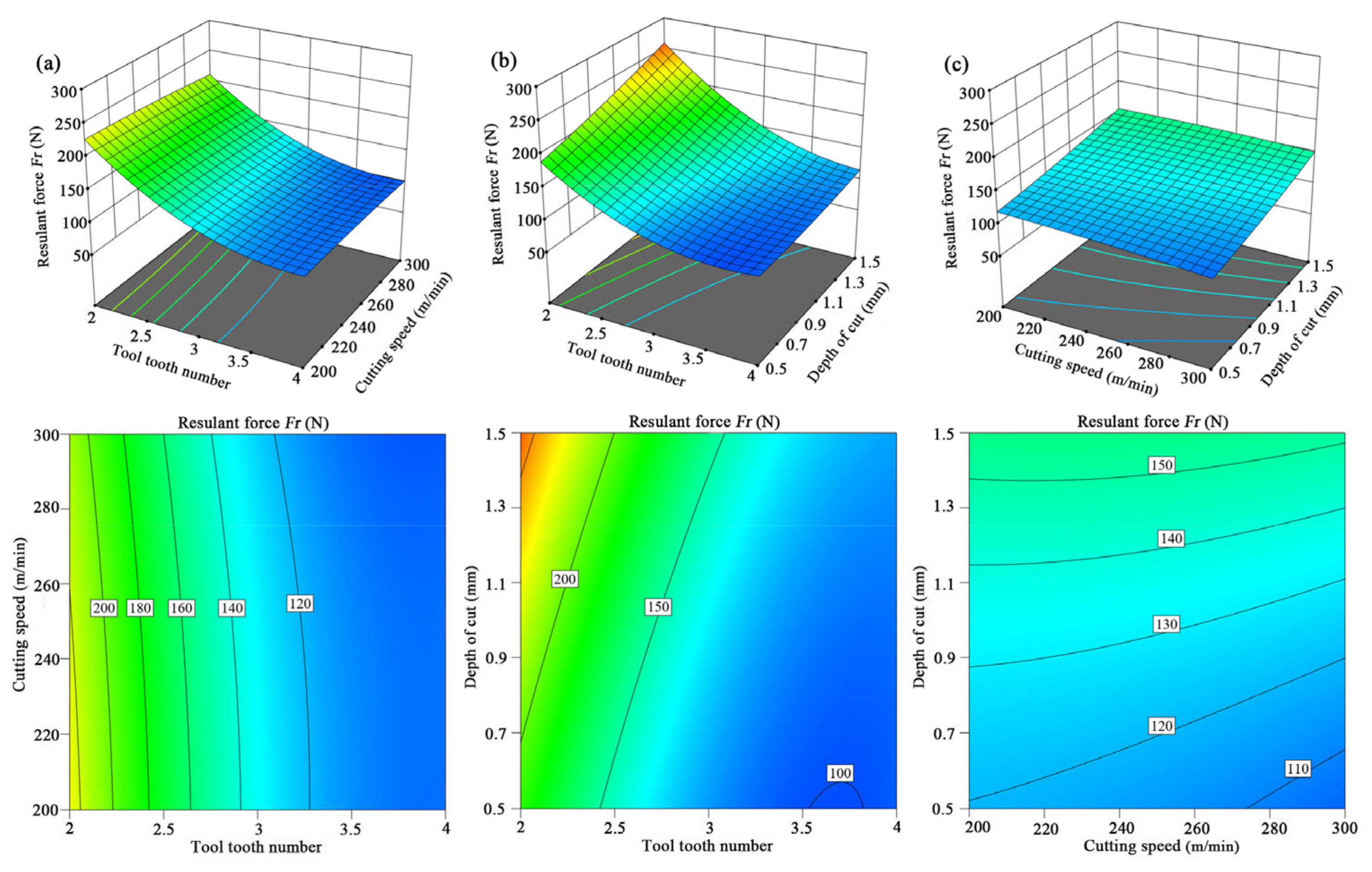
Figure 7.
Three-dimensional surface and contour maps of cutting temperature (a) tool tooth number and cutting speed, (b) tool tooth number and depth of cut, and (c) cutting speed and depth of cut.
Figure 7.
Three-dimensional surface and contour maps of cutting temperature (a) tool tooth number and cutting speed, (b) tool tooth number and depth of cut, and (c) cutting speed and depth of cut.

Figure 8.
Optimal milling conditions.

Table 1.
Properties of the workpieces.
| Flexural Strength | Moisture Content | Impact Strength | Tensile Strength | Density |
|---|---|---|---|---|
| 32.4 MPa | 1.01% | 16.8 KJ/m2 | 57 MPa | 9022 kg/m3 |
Table 2.
Tool geometries and properties of cutting tools.
| Rake Angle | Wedge Angle | Clearance Angle | Tool Diameter | Cutting Edge Radius |
|---|---|---|---|---|
| 12° | 68° | 10° | 8 mm | 0.02 mm |
| Blade length | Tool length | Bending strength | Hardness | Thermal conductivity |
| 45 mm | 106 mm | 1.35 GPa | 86 HRA | 72.4 W/m·K |
Table 3.
Cutting variables and their values.
| Cutting Variables | Number of Teeth | Cutting Speed (m/min) | Depth of Milling (mm) |
|---|---|---|---|
| Values of variables | 2, 3, 4 | 200, 250, 300 | 0.5, 1, 1.5 |
Table 4.
RSM design and results.
| Runs | Number of Teeth | Cutting Speed (m/min) | Depth of Milling (mm) | Resultant Force (N) | Cutting Temperature (°C) |
|---|---|---|---|---|---|
| 1 | 2 | 200 | 1.0 | 225.6 | 43.7 |
| 2 | 2 | 250 | 1.5 | 277.3 | 45.3 |
| 3 | 2 | 250 | 0.5 | 185.9 | 41.2 |
| 4 | 2 | 300 | 1.0 | 199.1 | 44.9 |
| 5 | 3 | 250 | 1.0 | 130.5 | 39.6 |
| 6 | 3 | 300 | 1.5 | 146.3 | 40.7 |
| 7 | 3 | 250 | 1.0 | 131.1 | 39.3 |
| 8 | 3 | 300 | 0.5 | 120.6 | 38.5 |
| 9 | 3 | 200 | 1.5 | 139.7 | 39.3 |
| 10 | 3 | 250 | 1.0 | 132.9 | 39.6 |
| 11 | 3 | 200 | 0.5 | 124.8 | 38.4 |
| 12 | 3 | 250 | 1.0 | 132.0 | 39.5 |
| 13 | 3 | 250 | 1.0 | 131.6 | 39.6 |
| 14 | 4 | 300 | 1.0 | 103.5 | 35.9 |
| 15 | 4 | 250 | 0.5 | 85.0 | 34.6 |
| 16 | 4 | 200 | 1.0 | 118.2 | 34.6 |
| 17 | 4 | 250 | 1.5 | 120.2 | 36.2 |
Table 5.
Model summary statistics for resultant force (Fr) and temperature (T) models.
| Models | Std. Dev. | C.V.% | Adeq Precision | R2 | Adj-R2 |
|---|---|---|---|---|---|
| Fr | 10.08 | 10.08 | 13.84 | 0.95 | 0.91 |
| T | 0.50 | 1.26 | 33.58 | 0.98 | 0.97 |
Table 6.
ANOVA for the resultant force (*: significant, p-value < 0.05).
| Source | Sum of Squares | df | % Cont. | Mean Square | F-Value | p-Value |
|---|---|---|---|---|---|---|
| Model | 35,552.00 | 9 | 95.84 | 3950.22 | 17.91 | 0.0005 * |
| z | 26,565.12 | 1 | 71.61 | 26,565.12 | 120.47 | <0.0001 * |
| vc | 188.18 | 1 | 0.51 | 188.18 | 0.85 | 0.3863 |
| ap | 3494.48 | 1 | 9.42 | 3494.48 | 15.85 | 0.0053 * |
| z × vc | 34.81 | 1 | 0.09 | 34.81 | 0.16 | 0.7030 |
| z × ap | 789.61 | 1 | 2.13 | 789.61 | 3.58 | 0.1003 |
| vc × ap | 29.16 | 1 | 0.08 | 29.16 | 0.13 | 0.7269 |
| z² | 4342.62 | 1 | 11.71 | 4342.62 | 19.69 | 0.0030 * |
| vc² | 19.19 | 1 | 0.05 | 19.19 | 0.09 | 0.7765 |
| ap² | 47.68 | 1 | 0.13 | 47.68 | 0.22 | 0.6561 |
| Residual | 1543.55 | 7 | 4.16 | 220.51 | ||
| Total | 37,095.56 | 16 | 100 |
Table 7.
ANOVA for cutting temperature (*: significant, p-value < 0.05).
| Source | Sum of Squares | df | % Cont. | Mean Square | F-Value | p-Value |
|---|---|---|---|---|---|---|
| Model | 156.47 | 6 | 98.45 | 26.08 | 105.74 | <0.0001 * |
| z | 142.80 | 1 | 89.85 | 142.80 | 579.02 | <0.0001 * |
| vc | 2.00 | 1 | 1.26 | 2.00 | 8.11 | 0.0173 * |
| ap | 9.68 | 1 | 6.09 | 9.68 | 39.25 | <0.0001 * |
| z × vc | 0.0025 | 1 | 0.002 | 0.0025 | 0.0101 | 0.9218 |
| z × ap | 1.56 | 1 | 0.98 | 1.56 | 6.34 | 0.0305 * |
| vc × ap | 0.4225 | 1 | 0.27 | 0.4225 | 1.71 | 0.2199 |
| Residual | 2.47 | 10 | 1.55 | 0.2466 | ||
| Total | 158.94 | 16 | 100 |
Table 8.
Verification of resultant force and temperature.
| Testing | Number of Teeth | Cutting Speed (m/min) | Depth of Milling (mm) | Resultant Force (N) | Cutting Temperature (°C) |
|---|---|---|---|---|---|
| Optimization | 4 | 300 | 0.5 | 95.9 | 35.0 |
| Verification | 4 | 300 | 0.5 | 88.6 | 33.1 |
| Error rate | / | / | / | −7.6% | −5.4% |
Disclaimer/Publisher’s Note: The statements, opinions and data contained in all publications are solely those of the individual author(s) and contributor(s) and not of MDPI and/or the editor(s). MDPI and/or the editor(s) disclaim responsibility for any injury to people or property resulting from any ideas, methods, instructions or products referred to in the content. |
© 2023 by the authors. Licensee MDPI, Basel, Switzerland. This article is an open access article distributed under the terms and conditions of the Creative Commons Attribution (CC BY) license (https://creativecommons.org/licenses/by/4.0/).
Share and Cite
MDPI and ACS Style
Song, M.; Buck, D.; Yu, Y.; Du, X.; Guo, X.; Wang, J.; Zhu, Z. Effects of Tool Tooth Number and Cutting Parameters on Milling Performance for Bamboo–Plastic Composite. Forests 2023, 14, 433. https://doi.org/10.3390/f14020433
AMA Style
Song M, Buck D, Yu Y, Du X, Guo X, Wang J, Zhu Z. Effects of Tool Tooth Number and Cutting Parameters on Milling Performance for Bamboo–Plastic Composite. Forests. 2023; 14(2):433. https://doi.org/10.3390/f14020433
Chicago/Turabian StyleSong, Meiqi, Dietrich Buck, Yingyue Yu, Xiaohang Du, Xiaolei Guo, Jinxin Wang, and Zhaolong Zhu. 2023. "Effects of Tool Tooth Number and Cutting Parameters on Milling Performance for Bamboo–Plastic Composite" Forests 14, no. 2: 433. https://doi.org/10.3390/f14020433
Note that from the first issue of 2016, this journal uses article numbers instead of page numbers. See further details here.