Article

SLAM-Aided Stem Mapping for Forest Inventory with Small-Footprint Mobile LiDAR

1
GNSS Research Centre, Wuhan University, No.129 Luoyu Road, Wuhan 430079, China
2
Department of Remote Sensing and Photogrammetry, Finnish Geospatial Research Institute FGI, Geodeetinrinne 2, Kirkkonummi FI-02431, Finland
3
Key Laboratory of Quantitative Remote Sensing Information Technology, Academy of Opto-Electronics, Chinese Academy of Science, No.9 Deng Zhuang Nan Road, Beijing 100094, China
4
Department of Computer Science, University of Helsinki, Gustaf Hällströmin katu 2b, Helsinki FIN-00014, Finland
5
Department of Forest Sciences, University of Helsinki, Yliopistonkatu 4, Helsinki FI-00100, Finland
6
Department of Real Estate, Planning and Geoinformatics, Aalto University, P.O. Box 11000, Espoo, FI-00076, Finland
7
Helsinki Metropolia University of Applied Sciences, Construction and Real Estate Hubic, Helsinki FI-00100, Finland
*
Author to whom correspondence should be addressed.
Forests 2015, 6(12), 4588-4606; https://doi.org/10.3390/f6124390
Submission received: 15 September 2015 / Revised: 24 November 2015 / Accepted: 8 December 2015 / Published: 17 December 2015

Abstract

:
Accurately retrieving tree stem location distributions is a basic requirement for biomass estimation of forest inventory. Combining Inertial Measurement Units (IMU) with Global Navigation Satellite Systems (GNSS) is a commonly used positioning strategy in most Mobile Laser Scanning (MLS) systems for accurate forest mapping. Coupled with a tactical or consumer grade IMU, GNSS offers a satisfactory solution in open forest environments, for which positioning accuracy better than one decimeter can be achieved. However, for such MLS systems, positioning in a mature and dense forest is still a challenging task because of the loss of GNSS signals attenuated by thick canopy. Most often laser scanning sensors in MLS systems are used for mapping and modelling rather than positioning. In this paper, we investigate a Simultaneous Localization and Mapping (SLAM)-aided positioning solution with point clouds collected by a small-footprint LiDAR. Based on the field test data, we evaluate the potential of SLAM positioning and mapping in forest inventories. The results show that the positioning accuracy in the selected test field is improved by 38% compared to that of a traditional tactical grade IMU + GNSS positioning system in a mature forest environment and, as a result, we are able to produce a unambiguous tree distribution map.

1. Introduction

With the development of Mobile Laser Scanning (MLS) technologies, detailed forest inventories based on Light Detection and Ranging (LiDAR) have become more practical than before. Building a tree map is very important and valuable for forest inventories [1,2,3]. Accurately locating positions would be a step towards automation of forestry operations, such as unmanned harvesters. Accurate tree mapping relies heavily on the accuracy of positions and attitude estimations of the vehicle platform. Combining Inertial Measurement Units (IMU) with Global Navigation Satellite Systems (GNSS) is a commonly-used positioning strategy in most MLS systems [4,5,6].
Using GNSS is a common strategy for various positioning tasks. Using Differential GPS (DGPS) or Real-Time Kinematic (RTK)-capable receivers is an option. However, these high-precision positioning methods, which work correctly in open sky environments, suffer severe signal loss in forests, where dense canopy absorbs, reflects or completely blocks the GNSS radio frequency (RF) signal, leading to degraded positioning results with errors of up to tens of meters. Such signal loss greatly hinders their capability to determine a reliable position in forests with GNSS-only positioning solutions [7]. Theoretically, dead reckoning (DR) in forests using IMU data is an alternative solution when GNSS is not available, when a detailed terrain model is available. However, wheel spin and slipping in forest environments will introduce accumulated errors [8], which cannot be corrected reliably. The lack of accurate and reliable positioning solutions in mature and dense forest environments highly restricts the level of automation.
SLAM, which is the process of generating a map of an unfamiliar environment and locating the mobile platform simultaneously, has been investigated in robotics for several decades. Several pilot studies on SLAM have been conducted [9,10,11,12,13,14] for forestry applications; most of the studies investigate the feasibility of using SLAM technology with a large beam divergence, with a spot size of tens of centimeters at a distance of 10–20 m [9,10,11]. Some effective enhanced algorithms have also been proposed to improve trunk estimation [9]; however, the performance is hardware-dependent. Due to the specifications like pulse width, angular resolution, and beam divergence are not identical, it is unlikely to offer a general enhanced algorithm for different LiDAR models. Small-footprint LiDAR is also adopted in forestry research in both Terrestrial Laser Scanning (TLS) and MLS configurations [15,16]; most studies utilize such scanners to model the trees rather than as a positioning sensor. Some studies have been performed in a controlled indoor environment and achieve promising and profound results [8]. However, the accuracy of such methods in a real forest is still largely unknown. How to conduct reliable and accurate positioning in forests poses still a challenge. Öhman et al. carried out a feasibility study for the utilization of LiDAR-based SLAM on a vehicle platform; however, the accuracy was not provided [12]. Jutila et al. [17] and Tang et al. [18] reported that the error increased with the ratio of the footprint of the laser scanning point to the size of the detected objects, proposing use of beam divergences smaller than 1 mrad for ranges s less than 100 m. This phenomenon was found in both indoor and outdoor SLAM applications. Chen et al. also reported that SLAM-based stem estimation results are satisfactory when the footprint size is smaller than the trunk size with a backpack laser scanner (BLS) [14]. This implies that for positioning in a forest, small-footprint lasers might offer better results. The major difference between this research and previous studies is that we investigated the accurate vehicle localization with small-footprint LiDAR. The small-footprint laser scanner utilized in this paper has the footprint size of a laser point smaller than the detected object (0.19 mrad). For example, in this research, the maximum footprint size we used for SLAM was less than 1 cm, which is smaller than most trunks in the forest.
The contributions of this paper are as follows: (1) we investigate small-footprint LiDAR-based SLAM for positioning a vehicle in different forest environments; (2) we succeed in locating the stems in a mature and dense boreal forest with a SLAM + IMU solution, with positioning accuracy better than 0.32 m over an approximately 300 m course; (3) an accurate and unique stem map is generated with the SLAM-aided method.
The remainder of this paper is organized as follows: Section 2 describes the methods utilized in this research; Section 3 introduces the field tests; the experimental results are discussed in Section 4; and Section 5 draws conclusions.

2. Methods

Presently, the localization/georeferencing of MLS is carried out with GNSS + IMU. GNSS is strongly affected by the presence of tall, dense trees. With good GNSS conditions, the reported height and horizontal accuracy of MLS data are 2–4 cm [19], and the best laser systems provide a ranging error of 2 mm. However, in some cases, errors of several meters are possible. The accuracy of MLS positioning in forests is addressed in research only until recently [20]. Therefore, we attempt to (1) analyse MLS positioning accuracy inside forests; (2) determine GNSS accuracy inside forests; (3) and study alternative positioning technologies in forests, such as SLAM, and its integration with GNSS + IMU. The logic for using GNSS, IMU and SLAM inside forests is depicted in Table 1.
Table 1. Logic for different cases of positioning in forests.
Forest TypeGNSSSLAMIMUResearch Questions?
Open forestWorksdoes not workWorks but there is driftTo use GNSS + IMU, no research need.
Mature but scattered forest with reasonably low vegetationShould work to certain levelShould workWorks but there is driftQuestion is can GNSS + SLAM be used as a direct georeferencing tool
Mature dense forests with reasonably low vegetationMay not work properlyShould workWorks but there is driftCan SLAM improve GNSS + IMU solution in these cases?
In this paper, we conduct research based on field test data collected in the Evo test field located in Southern Finland and comprises mainly managed boreal forest. The major tree species in the test field are pine, birch, and spruce. The data were collected by the FGI ROAMER R2 mobile mapping system, which was installed rigidly on a vehicle platform [21]. Since it is difficult to quantitatively define the effects of dense mature and scattered mature forest for the GNSS visibility, and as the GNSS constellation is time-varying, in this research we simplify the problem by merging these two forest types into one type: mature forest.

2.1. MLS System for Research

Figure 1 shows the FGI ROAMER R2 mobile mapping system placed on an all-terrain-vehicle (ATV), which is utilized in this research. The system consists of a NovAtel SPAN navigation system, which includes a GNSS receiver (NovAtel Flexpak6), an IMU (NovAtel UIMU-LCI), and a high-speed phase-shift LiDAR (FARO Focus3D 120S). All sensors are mounted on a rigid platform to perform 3D mapping of the forest. The LiDAR sensor adopted for SLAM research is the FARO Focus3D X330, mounted horizontally into backward looking position. The beam divergence of FARO Focus3D X330 is 0.011° (0.19 mrad), and the beam diameter at exit is 2.25 mm. The maximum range measurement utilized in this research was 25 m, resulting in a maximum footprint size of 7.3 mm (was smaller in comparison to 10–20 cm of large beam divergence scanners). The raw laser point cloud data are in a scanner coordinate system. These raw observations are synchronized with the vehicle positions and transformed to real world three-dimensional (3D) coordinates. The synchronization is obtained by utilizing synchronized pulse of the LiDAR to trigger an event pin of the navigation device.
Figure 2 describes the data process flow of the proposed SLAM-aided stem mapping system. First, laser scans from LiDAR and the attitude from IMU are synchronized with GPS time. Then, each laser scan is projected to a 2D plane according to the attitude measurements. Finally, the processed laser scans are imported to a SLAM software system for post-positioning and mapping. The details of projecting and SLAM scan matching algorithms are described in the following sections.
Figure 1. ATV with mounted devices including GNSS antennas and receivers, IMU and LiDAR.
Forests 06 04390 g001
Figure 2. The data process flow of the SLAM-aided stem mapping system.
Forests 06 04390 g002

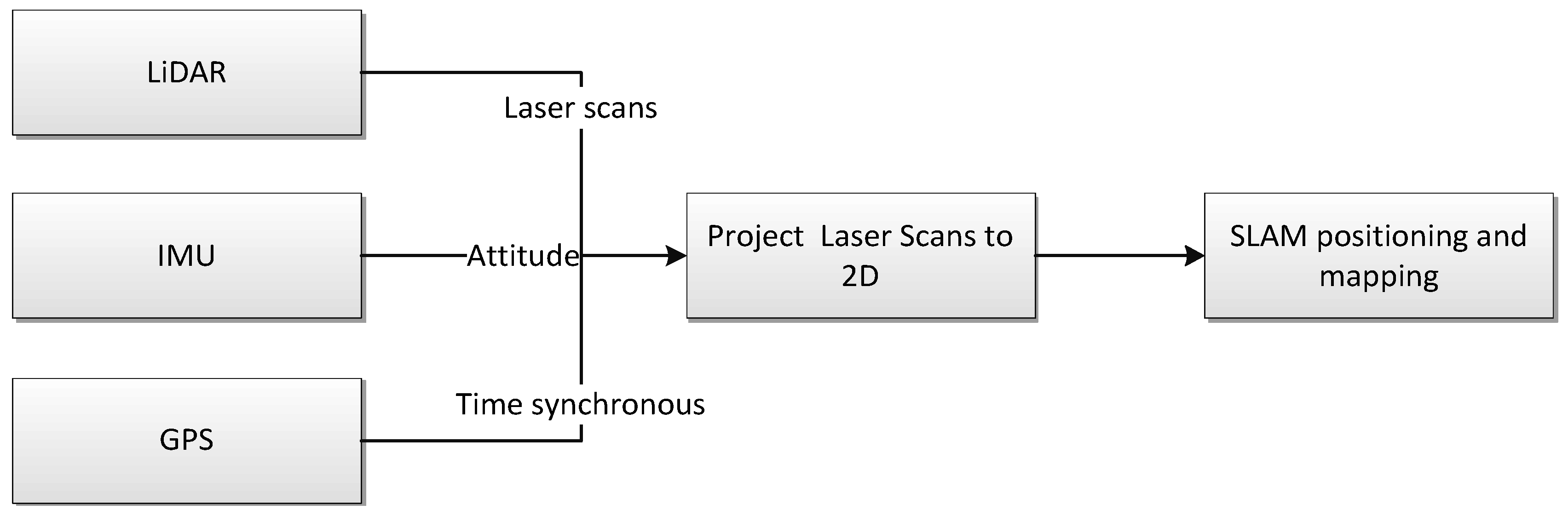
2.2. SLAM Developed for Forestry

The SLAM problem is the process of mapping an unknown environment sensed by range sensors, such as laser scanners and sonars rigidly installed on a moving platform while simultaneously constructing the map and determining the sensor location on the map. The method combines positioning and mapping problems in a single framework, and SLAM is considered to be an effective method for resolving positioning and environment-recognizing problems and has been investigated in robotics for two decades [22]. There are two major strategies for determining positions with SLAM: absolute positioning with feature-matching and relative positioning with scan-matching. Theoretically, the first method extracts features from range scans, such as lines, corners, and semicircles of tree trunks, and then matches the extracted known features with a generated feature map to recognize the position. In relative positioning, on the contrary, scan matching utilizes two or more consecutive frames of scan points to directly obtain the movement mobile platform with various algorithms, e.g., classical Iterative Closest Point (ICP) [23], Iterative Closest Line (ICL) [24], Monte Carlo [25], and Maximum Likelihood Estimation (MLE) [26,27]. SLAM is mainly utilized in robotics for various indoor applications. However, the research of using SLAM in forestry is still far from to be used as an operational positioning solution for a mobile platform. Compared with indoor environments with regular and persistent features, such as corners and straight corridors, forest growth in natural conditions is more complex due to features such as undergrowth and irregular terrain and rocks. These features will introduce abrupt movements and thus noise to the data, which obviously increases the computation payload and the complexity of the algorithm design. Thus the SLAM algorithms utilized for forestry applications should be more robust to cope with various imperfect environment situations.
Moreover, some premises have to be taken into account to refine the research problems and focus on the essential parts of the problems: (1) the system running in a boreal forest in Nordic countries where pine, birch, and spruce are the dominating species; and (2) cases in which most mature stems have straight and circular stems. Otherwise, we cannot project multiple segmental laser scans from 3D spatial space onto 2D stem profiles to generate the stem map, as presented in Figure 3, according to the attitude provided by the IMU data.
Figure 3. Illustration of projecting a 3D point cloud on the trunk onto a 2D map for stem location [14].
Forests 06 04390 g003
The proposed LiDAR SLAM scan-matching algorithm, the Improved Maximum Likelihood Estimation (IMLE), is a probabilistic and feature uncertainty model-based grid map matching method: As is shown in Figure 4, a quad-tree pyramid structure likelihood map M stores the likelihood value created from the previous laser scans, which represent the possibility of a given environment’s geometries. Then, the incoming new scan S t is matched against the map to find the best body transformation T * , where the entire scan provides the maximum likelihood value P ( S t | M ) . The likelihood value P ( p i | M ) of a single point p i on a map M is proportional to the distance d to the nearest environmental feature F, according to the Gaussian probability model of laser-measured noise with a scale parameter σ . To avoid complicated computing, a simplified four-level model of likelihood of a single point p i is predefined as (0.1, 0.3, 0.6 and 0.9). It is given according to distance d to point p i .
P ( p i |M ) e ( d ( p i , F ) / σ )
P ( S t |M ) = i = 1 n P ( p i |M )
T * = argmax ( P ( T S t | M ) )
Figure 4. The pyramid structure of the likelihood map and LiDAR scan-matching example of the IMLE algorithm.
Forests 06 04390 g004
Based on the above model, an optimum refined local search algorithm is deployed to estimate the best body transformation   T * within the entire map M from the previous state. Figure 4 also shows an example of the IMLE scan-matching process. The red rectangle points show the current scan, which searches the local area of the background likelihood map with a given searching range and angle resolution to determine the optimum position and attitude with the maximum likelihood values. More details of the IMLE and its performance can be found in our previous works [27,28].

3. Field Test

For the evaluation, a test field featuring different types of forest stands was established in Evo, Southern Finland (61°19′ N, 25°11′ E). The area belongs to the southern boreal forest zone and comprises approximately 2000 ha of managed boreal forest. However, Evo is also a popular recreation area, which distinguishes it from totally homogenous managed forests and provides a cross-section from natural to intensively managed southern boreal forests. The average stand size in the area is slightly less than one hectare. Scots pine and Norway spruce are the dominant tree species, and the site quality varies from groves to barren heaths.
The positions of 224 trees (green points in Figure 5) along the driving route were measured using a total station and RTK GPS. The location accuracy of the reference targets was estimated to be better than 10 cm in a 2D coordinate system (EastingNorthingETRS-TM35FIN). These trees were used as a reference object network to evaluate the accuracy of the computed trajectories. In addition to the GNSS and IMU, a scanner was horizontally mounted at the back of the ATV. Thus, when a laser point cloud was generated using the recorded GNSS and IMU observations and laser scan measurements, the positions of the reference trees could be measured from the point cloud. Then, the accuracy of the post-processed GNSS + IMU trajectory could be evaluated. All data for reference and test trajectory were collected simultaneously. The average speed of the ATV was approximately 4 km/h. The reference positions of the trees were measured in the field at breast height. The breast height was determined as 1.3 m above the average ground level around the tree.
Figure 5. Reference trajectory (red) and reference trees (green) (Background orthoimage: NLS 2012).
Forests 06 04390 g005
The whole field test trajectory is a round trip, which starts from A (open forest) to B (dense forest), C (open forest), D (dense forest) and E (dense forest), then back to A through D, C and B, and is about 1 km long in total. The yellow arrows show the test route in Figure 5. In this study, in addition to the whole trajectory of the driving test, two sub-trajectories of B-C-D and D-E were selected to evaluate the proposed SLAM-aided positioning and mapping method under different canopy conditions. B-C is an open forest near a lake and a paved road with only a few saplings within the 25 m sensing radius, where the GNSS satellite view is good; D-E is almost shadowed in the dense canopies, where GNSS signals are almost completely lost.

4. Results and Discussion

Positioning and mapping results are evaluated with various positioning solutions including GNSS only, GNSS + IMU, and the proposed SLAM + IMU. Since the true trajectory of the field test cannot be directly measured by the on-board georeference sensor, the positioning trajectories of GNSS + IMU and SLAM + IMU solutions are indirectly evaluated with the aforementioned reference object networks consisting of the coordinates of 224 trees along the driving route whose locations are derived from total station measurements. Figure 6 presents the adopted method utilized for the accuracy evaluation. The positioning error E is calculated by the reference network with
E = i = 1 N d i 2 N  (r < R)
where d i   is the centre offset of the i -th reference tree within the effective LiDAR range. However, because the stem map cannot be generated with a GNSS-only positioning solution, we present only the post-processing VRS (Virtual Reference System) position result.
Figure 6. Tree Reference network for evaluating the positioning accuracy of the ATV trajectory.
Forests 06 04390 g006

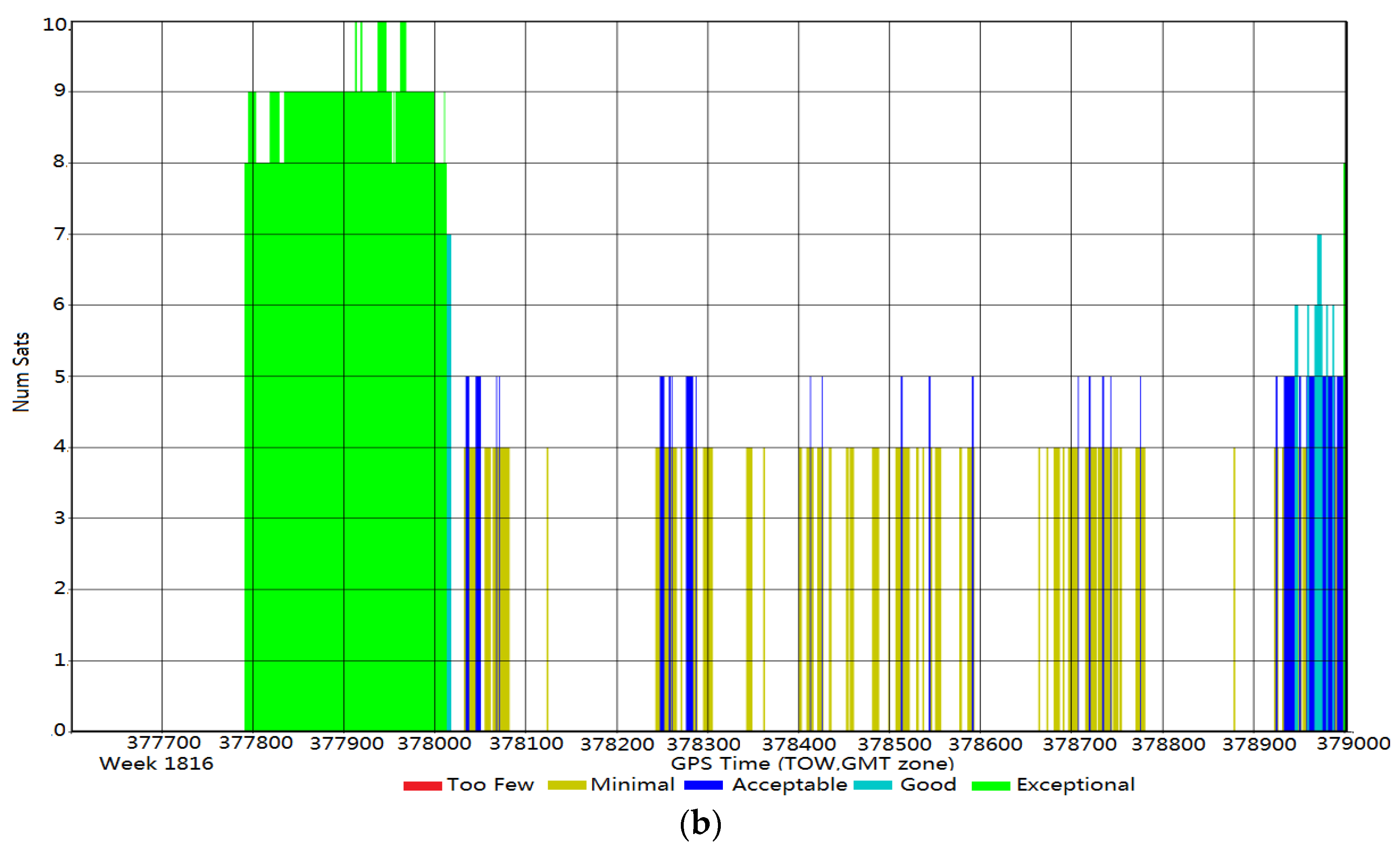
4.1. The Positioning Accuracy of the GNSS Only and GNSS + IMU Solutions

Figure 7a shows the estimated positioning standard deviation of the GNSS-only solution in local east-north coordinates, and Figure 7b presents the number of satellites available for positioning. As is illustrated in the plot, the positioning results are not continuous because the GNSS signal is not always available along the driving route as the multiple dot line rectangles mark the figure. The duration of the driving test is 1039 s and the GNSS-only solution avails the positioning for 346 s coverage. The GNSS availability was 33.3% during the test. Only 75 epochs have enough satellite observations (satellite number ≥6) during the test run. From Figure 7a, it can be observed that most of the good observations are on the end part of the trajectory, where the ATV progressed in fairly open young forest (E in Figure 5). In thick canopy areas, the GNSS signal loss time can last approximately two minutes, which is approximately equal to a 120 m of trajectory, as indicated by the red dot rectangle in the plot. This means that GNSS cannot provide positioning results for laser scan mapping during these time periods. Due to such blocks, attenuations and multipath effects, the accuracy of the trajectory with the GNSS-only solution was 5.82 m during the available period computed by Waypoint Inertial Explorer software with Virtual Reference Station (VRS) technology where a network of reference stations was used to compute a virtual reference for a location close to the test site, as shown in Table 2. More detailed information about the accuracy of kinematic positioning using different GNSS receivers in the Evo field test can be found in [20].
Figure 7. (a) Position accuracy and (b) satellite observability of the GNSS-only solution.
Forests 06 04390 g007aForests 06 04390 g007b
Table 2. The accuracy of the trajectory in the EVO test site (Unit: m).
RMSE (m)EastingNorthing2D
GNSS only3.154.895.82
GNSS + IMU0.510.350.62
GNSS + IMU is the most popular and practical positioning method of traditional MLS systems for sustainable navigation in forests. The GNSS + IMU trajectory was computed using the Waypoint Inertial Explorer commercial software (Calgary, Alberta, Canada). The reference GNSS data were downloaded from the Trimnet GNSS service to a virtual reference station close to the test site. Thus the point cloud can be derived from the trajectory and inertial measurements. The accuracy of the GNSS + IMU trajectory was determined by comparing the tree locations calculated from the total-station measurements with those measured from the point cloud [20]. Table 2 also shows the post-processed results of the NovAtel SPAN system. The positioning RMSEs of the whole trajectories were 0.51 (Easting), 0.35 (Northing), and 0.62 (2D) meters at the test site, which implies the GNSS + IMU method is able to achieve an accuracy level of roughly half a meter in a mature boreal forest environment. Furthermore, a comprehensive comparison and analyses between the proposed SLAM + IMU method and the traditional GNSS + IMU method will be described in the following sections.

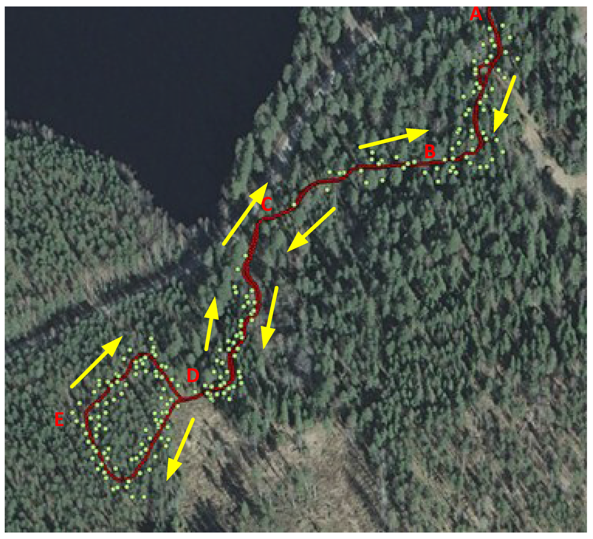
4.2. Evaluation of the Entire Test Path

Figure 8a shows the trajectories and stem position comparison between the GNSS + IMU and SLAM + IMU methods for the entire trajectory. The comparison of positioning accuracy of the GNSS + IMU and SLAM + IMU methods for the entire path is presented in Figure 8b. The SLAM + IMU solution is effective in B (dense forest), where the positioning error is moderate. The positioning error greatly diminished when the ATV drove from B (dense forest) to C (open forest). The error accumulated in an open forest section cannot be mitigated even if the ATV drove back to the dense forest (D, E) again. Without external information to fix the drift, the SLAM-only solution cannot offer a robust positioning means in forests. There are several potential solutions to alleviate the position drift: (1) introduce GNSS measurements to the positioning framework because GNSS observations are better in an open forest; (2) adaptively adjust the SLAM algorithm parameter, e.g., extend the search scope or adopt a finer search parameter; or (3) integrate more navigation sensors.
In the following section, we separate the entire test trajectory into two sub-trajectories to study how the SLAM solution works in different forest environments and the accuracy therein. Thus, the criteria of how to utilize SLAM in forests can be investigated.

4.3. Evaluation in an Open Forest Area

The first sub-trajectory was designed as moving from a mature forest area to an open forest, then to another mature forest area. As is shown in Figure 5 and Figure 8a, the route B-C-D is near a lake and a paved road, where only a few saplings grow within the 25 m scanner range threshold. It can be recognized as an open forest in which GNSS signals are well received (see Figure 7b).
The vehicle trajectories in the green rectangle of Figure 9 show that there is a sudden error jump in the SLAM + IMU trajectory (blue dots), when the vehicle moved from the mature forest area to the open forest, where there are fewer tree features, especially at C. It is well known that SLAM technology relies heavily on the features of the environment, and if there are not sufficient matching features, the positioning results deteriorate quickly. Figure 10a presents the comparison of position errors of the SLAM + IMU and GNSS + IMU methods in an open forest. The positioning error of the GNSS + IMU is consistent during the test and the figure of SLAM + IMU start to diminish when the ATV enters from mature forest to open forest. The positioning error increase exponentially and cannot be mitigated when the ATV reach mature forest again. Figure 10b shows the stem positioning errors of a series of selected trees along the sub-trajectory. In the dense forest area, the positioning errors of trees (209, 194, 199, 210, 214, 223 and 222) from both methods are almost the same. However, the result of the SLAM + IMU method deteriorates quickly, whereas the accuracy of the GNSS + IMU solution persists when encountering an open forest. Finally, the accuracy of this test trajectory is given in Table 3: the RMSEs of GNSS + IMU were 0.36 (Easting), 0.19 (Northing) and 0.40 (2D) meters; and the RMSEs of SLAM + IMU are 1.73 (Easting), 2.33 (Northing) and 2.90 (2D) meters.
From the above results, a conclusion can be drawn that SLAM technology is not an applicable sole positioning solution in an open forest where abundant strong GNSS signals are accessible while less matching features are available. This however warrants a question whether using longer range threshold would have helped the solution consistency. It is also to be noted, that the terrain at C has large elevation changes down from B to C and turns back uphill, which may also have played a role in detecting tree truncks for continuous matching.
Figure 8. (a) Trajectories and stem position comparison between the GNSS + IMU and SLAM + IMU methods for the entire test and (b) positioning errors of the SLAM + IMU solution for the entire test.
Forests 06 04390 g008
Figure 9. Trajectory and stem position comparison between the GNSS + IMU and SLAM + IMU methods in an open forest environment. Green dots are the trajectory of GNSS + IMU; blue dots are the trajectory of SLAM + IMU; red triangles are the reference tree position; green triangles are the tree positions calculated with the GNSS + IMU method; blue triangles are the tree positions calculated with the SLAM + IMU method. Lack of trees to the left of the trajectory is obvious.
Forests 06 04390 g009
Figure 10. (a) Positioning errors of the SLAM + IMU solution in an open forest; (b) stem position errors along the trajectory between the GNSS + IMU and SLAM + IMU methods in an open forest environment.
Forests 06 04390 g010
Table 3. The accuracy of the trajectory in a featureless area with 52 trees (Unit: m).
SolutionRMSE
EastingNorthing2D
GNSS + IMU0.360.190.40
SLAM + IMU1.732.332.90

4.4. Evaluation in a Mature Forest Area

The second sub-trajectory is from a completely mature forest area following the first route. In this area, most of the route is shaded by mature pine and spruce trees (from C to D, loop E is young pine forest). The GNSS signal loss is stronger than in the previous area (see site C in Figure 7a). The dead reckoning of IMU is the main navigation approach for the GNSS + IMU solution. Figure 11 shows the trajectories and tree stem position between the GNSS + IMU and SLAM + IMU methods in such a feature-rich environment. It can be observed that the trajectories (blue and green dots) and the tree stem positions (blue, green and red triangles) are consistent. The trajectory of the SLAM + IMU method is smooth and has no abrupt jumps during the four min run time compared with Figure 9. The result demonstrates that SLAM technology can be used as a potential alternative dead reckoning navigation approach to the GNSS + IMU approach.
Positioning accuracy of the trajectories of GNSS + IMU and SLAM + IMU are evaluated in Figure 12a and Table 4. The position error of the GNSS + IMU method is higher than that of the SLAM + IMU method in dense forest. It is interesting to find out the opposite tendencies of the two positioning methods in Figure 12a which also proves that the two positioning methods are complementary to in real forest environment. As is shown in Figure 12b, a series of trees (11 samples) are selected along the test route to conduct the position accuracy comparison. The errors of the first six sampling trees (34, 51, 54, 67, 47 and 81) with the GNSS + IMU method are obviously greater than those with the SLAM + IMU method. This occurs in the area shaded by mature trees (the area D in Figure 11) where the GNSS signals were completely lost but abundant tree trunk features were available for the SLAM processing. The differences of the positioning errors for the latter five trees (105, 114, 120, 147 and 136) are not so obvious because the forest density is relatively scattered (the area E in Figure 11). The GNSS signal was available occasionally when the ATV passed underneath the saplings. The trajectory RMSEs of the GNSS + IMU are 0.36 (Easting), 0.32 (Northing), and 0.52 (2D) meters, whereas those of the SLAM + IMU method are 0.16 (Easting), 0.27 (Northing), 0.32 (2D) meters in this mature forest area. The accuracy of the SLAM + IMU method is 38% higher than the GNSS + IMU method in this environment and is especially improved in the mature forest where the canopies totally block the GNSS signal. In such an environment, the positioning error of the IMU-based dead reckoning will drift exponentially because of the inherent error of IMU. One issue that has been addressed is that although we utilize the measurement of a tactical grade IMU in the SLAM + IMU method, a consumer grade IMU is also applicable [18].
Figure 11. Trajectories and stem position comparison between the GNSS + IMU and SLAM + IMU methods in a feature-rich environment. Green dots are the trajectory of GNSS + IMU; blue dots are the trajectory of SLAM + IMU; red triangles are the reference tree position; green triangles are the tree positions calculated by the GNSS + IMU method; blue triangles are the tree positions calculated by the SLAM + IMU method.
Forests 06 04390 g011
Figure 12. (a) Comparison of positioning errors between the SLAM + IMU and GNSS + IMU methods in a dense and mature forest; and (b) stem position error along the trajectory between the GNSS + IMU and SLAM + IMU methods in a mature forest environment.
Forests 06 04390 g012
Table 4. The accuracy of the trajectory in a mature forest area with 142 trees (Unit: m).
RMSE (m)EastingNorthing2D
GNSS + IMU0.360.320.52
SLAM + IMU0.160.270.32

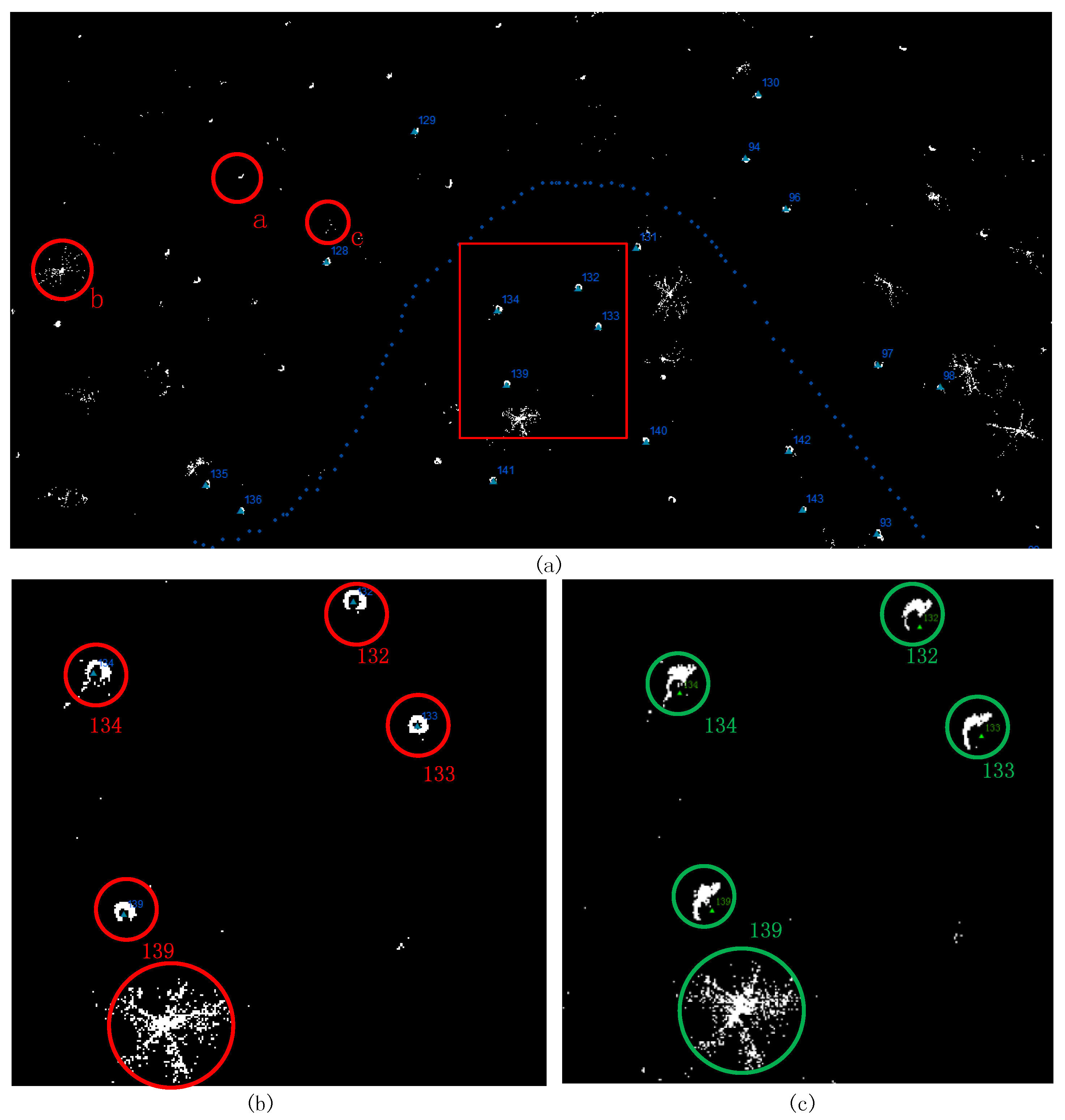
4.5. Evaluation of the Tree Stem Distribution Map

As mentioned above, generating an accurate and unique tree distribution map is one of the most important purposes for forest inventories. With a reliable map, it is also possible to automatically extract more complex tree parameters, such as the diameter at breast height (DBH) and tree species. Figure 13 shows a comparison of results of stem distribution maps generated using the GNSS + IMU and SLAM + IMU methods. Figure 13a shows an overview map generated along a short secion of the trajectory, in which the tree stem arcs and circles are formed with white dots from the laser point cloud. In general, the 2D point clouds can be clustered in three types of geometric shapes: (a) a short arc or circle, which is detected as a pine/birch tree trunk; (b) a star-like shape, which is detected as a spruce; and (c) noise points, such as rocks or bushes. Figure 13b,c show the mapping results of the red rectangle area of Figure 13a using the GNSS + IMU and SLAM + IMU methods, respectively. The pine tree (132, 133, 134, and 139) arcs and circles within the red circles are clearer and more recognizable than those seen in the green circles. The main reason for this improved clarity is that the inherent error introduced by IMU is mitigated by scan matching processing of consecutive laser scans. Thus, the position error of the sensor is is alleviated by the SLAM + IMU. On the contrary, the positioning errors in the GNSS + IMU method are propagated to the mapping results without any correction.
Figure 13. (a) Tree stem map generated with the SLAM + IMU method in a mature forest environment; (b) map generated with the SLAM + IMU method in the red rectangle area; (c) map generated with the GNSS + IMU method in the red rectangle area (white dots are the laser point cloud).
Forests 06 04390 g013
However, it seems there are not too many differences in terms of the shape of the detected spruce with the above two methods. In both cases, the shape can be easily recognized. It is also found that trees with branches all the way down, like spruce typically, will cause scattered points around the stem, which will negatively impact on the laser scan-matching and may even reduce the matching accuracy.

5. Conclusions

In summary, the possibility of using a SLAM technology-aided MLS system with a small-footprint LiDAR for forest navigation and inventory is investigated in this paper. The laser scans are projected to a 2D plane with attitude information provided by an IMU. Then, a likelihood map-based IMLE 2D scan-matching algorithm is adopted for position estimation and tree distribution map generation. Field tests in an open forest and mature forest were conducted to evaluate the method’s ability to position and map in a boreal forest. The accuracy of SLAM-based vehicle localization method is evaluated with ROAMER MLS. A small footprint LiDAR is utilized to collect the data in a managed boreal forest in Southern Finland. The accuracy of the trajectory based on the SLAM + IMU method in a mature and dense forest is 0.32 m after a four-min run time. As a comparison, the accuracy of a tightly coupled positioning solution offered by a tactical grade IMU and GNSS with a Virtual Reference Station (VRS) in such forests is 0.52 m.
The experiment results are promising. (1) The positioning accuracy can achieve 0.32 m in RMSE with SLAM + IMU scan-matching in a mature forest, where there are enough tree trunk features. The performance is approximately 38% better than the traditional GNSS + IMU method in the test field. Unfortunately, in the open forest area, SLAM cannot operate as well as in the mature forest because the open forest area lacks matching features, and without external information, the accumulated drift diminishes the position accuracy. The sloping terrain also plays a role in this, as the stem detection becomes more uncertain especially when the vehicle has large roll or pitch (up to 20 degrees), or the terrain has elevation changes larger than the SLAM sensor elevation from the ground, both limiting the scanner visibility, given the SLAM sensor is aligned with the vehicle horizon. However, strong GNSS signals can normally be received in open or sparse forest areas, and adding this information to the processing possess a future work task. The platform has an alternative position solution in addition to SLAM: GNSS and SLAM can be a complementary method in forest positioning and navigation; (2) the proposed SLAM-aided mapping method can produce a more accurate and unambiguous tree trunk map on the premise that there are not too many branches at breast height to disturb the stem detection. Then, tree trunk information such as DBH and location can be extracted correctly.
Only attitude information of IMU is integrated with SLAM scan matching in this work. An EKF-based LiDAR and IMU fused navigation framework were also proposed in our previous paper [28]. Therefore, in the future work, GNSS, LiDAR-based SLAM and IMU will be integrated with a uniform EKF framework for more accurate positioning and mapping of an MLS system.

Acknowledgments

This study was financially supported by the Academy of Finland projects “Towards Precision Forestry”, “Centre of Excellence in Laser Scanning Research (CoE-LaSR) (272195)”, “Interaction of Lidar/Radar Beams with Forests Using Mini-UAV and Mobile Forest Tomography”, by the Chinese Academy of Science (181811KYSB20130003), by Chinese Ministry of Science and Technology (2015DFA70930) and the National Nature Science Foundation of China (41304004). The research leading to these results has received funding from the European Community’s Seventh Framework Programme (FP7/2007–2013) under grant agreement n 606971; Academy of Finland project “Competence-Based Growth Through Integrated Disruptive Technologies of 3D Digitalization, Robotics, Geospatial Information and Image Processing/Computing—Point Cloud Ecosystem (293389) and European Union, the European Regional Development Fund, “Leverage from the EU 2014-2020” projects “AKAI” (301130).

Author Contributions

Jian Tang and Yuwei Chen conceived and designed the experiments and wrote the paper, performed the experiments; Antero Kukko, Anttoni Jaakkola, Harri Kaartinen, built the MLS system, performed the field test and provided the LiDAR, IMU, GPS raw data and tree reference; Ehsan Khoramshahi and Teemu Hakala contributed analysis tools and data analysis; Juha Hyyppä, Markus Holopainen and Hannu Hyyppä, supervised the study and reviewed the paper.

Conflicts of Interest

The authors declare no conflict of interest.

References

  1. Bienert, A.; Scheller, S.; Keane, E.; Mohan, F.; Nugent, C. Tree detection and diameter estimations by analysis of forest terrestrial laser scanner point clouds. In ISPRS Workshop on Laser Scanning; IAPRS: Espoo, Finland, 2007; Volume 2007, pp. 50–55. [Google Scholar]
  2. Brolly, G.; Kiraly, G. Algorithms for stem mapping by means of terrestrial laser scanning. Acta Silv. Lignaria Hung. 2009, 5, 119–130. [Google Scholar]
  3. Holopainen, M.; Vastaranta, M.; Hyyppä, J. Outlook for the Next Generation’s Precision Forestry in Finland. Forests 2014, 5, 1682–1694. [Google Scholar] [CrossRef]
  4. Kukko, A.; Kaartinen, H.; Hyyppä, J.; Chen, Y. Multiplatform mobile laser scanning: Usability and performance. Sensors 2012, 12, 11712–11733. [Google Scholar] [CrossRef]
  5. Holopainen, M.; Kankare, V.; Vastaranta, M.; Liang, X.; Lin, Y.; Vaaja, M.; Alho, P. Tree mapping using airborne, terrestrial and mobile laser scanning–A case study in a heterogeneous urban forest. Urban For. Urban Green. 2013, 12, 546–553. [Google Scholar] [CrossRef]
  6. Roßmann, J.; Krahwinkler, P.; Schlette, C. Navigation of mobile robots in natural environments: Using sensor fusion in forestry. J. Syst. Cybern. Inform. 2010, 8, 67–71. [Google Scholar]
  7. Bilker, M.; Kaartinen, H. The quality of real-time Kinematic (RTK) GPS positioning. Rep. Finn. Geod. Inst. 2001, 1, 1–25. [Google Scholar]
  8. Fuke, Y.; Krotkov, E. Dead reckoning for a lunar rover on uneven terrain. In Proceedings of the IEEE International Conference on Robotics and Automation, Minneapolis, MN, USA, 22–28 April 1996; Volume 1, pp. 411–416.
  9. Ringdahl, O.; Hohnloser, P.; Hellström, T.; Holmgren, J.; Lindroos, O. Enhanced Algorithms for Estimating Tree Trunk Diameter Using 2D Laser Scanner. Remote Sens. 2013, 5, 4839–4856. [Google Scholar] [CrossRef]
  10. Takashi, T.; Asano, A.; Mochizuki, T.; Kondou, S.; Shiozawa, K.; Matsumoto, M.; Tomimura, S.; Nakanishi, S.; Mochizuki, A.; Chiba, Y.; et al. Forest 3D Mapping and Tree Sizes Measurement for Forest Management Based on Sensing Technology for Mobile Robots. In Field and Service Robotics; Springer: Berlin, Germany; Heidelberg, Germany, 2014. [Google Scholar]
  11. Ding, X.; Yan, L.; Liu, J.; Kong, J.; Yu, Z. Obstacles Detection Algorithm in Forest based on Multi-sensor Data Fusion. J. Multimed. 2013, 8, 790–795. [Google Scholar] [CrossRef]
  12. Öhman, M.; Miettinen, M.; Kannas, K.; Jutila, J.; Visala, A.; Forsman, P. Tree measurement and simultaneous localization and mapping system for forest harvesters. In Field and Service Robotics; Springer: Berlin, Germany; Heidelberg, Germany, 2008; pp. 369–378. [Google Scholar]
  13. Miettinen, M.; Ohman, M.; Visala, A.; Forsman, P. Simultaneous Localization and Mapping for Forest Harvesters. In Proceedings of the IEEE International Conference on Robotics and Automation, Roma, Italy, 10–14 April 2007; pp. 517–522.
  14. Chen, Y.; Tang, J.; Hyyppä, J.; Holopainen, M.; Liang, X.; Liu, J.; Chen, L.; Hakala, T.; Litkey, P.; Niu, X.; et al. Automated Stem Mapping Using SLAM Technology for Plot-Wise Forest Inventory. In Proceedings of Ubiquitous Positioning Indoor Navigation and Location-Based Services (UPINLBS 2014), Corpus Christi, TX, USA, 20–21 Novenber 2014; pp. 130–134.
  15. Liang, X. Feasibility of Terrestrial Laser Scanning for Plotwise Forest Inventories. Ph.D. Thesis, Publication of the Finnish Geodetic Institute, Masala, Finland, 2013. [Google Scholar]
  16. Liang, X.; Litkey, P.; Hyyppä, J.; Kaartinen, H.; Kukko, A.; Holopainen, M. Automatic plot-wise tree location mapping using single-scan terrestrial laser scanning. Photogramm. J. Finl. 2011, 22, 37–48. [Google Scholar]
  17. Jutila, J.; Kannas, K.; Visala, A. Tree measurement in forest by 2D laser scanning. In Proceedings of the IEEE International Symposium on Computational Intelligence in Robotics and Automation, Jacksonville, FL, USA, 20–23 June 2007; pp. 491–496.
  18. Tang, J.; Chen, Y.; Chen, L.; Liu, J.; Hyyppä, J.; Kukko, A.; Chen, R. Fast Fingerprint Database Maintenance for Indoor Positioning Based on UGV SLAM. Sensors 2015, 15, 5311–5330. [Google Scholar] [CrossRef] [PubMed]
  19. Kaartinen, H.; Hyyppä, J.; Kukko, A.; Jaakkola, A.; Hyyppä, H. Benchmarking the performance of mobile laser scanning systems using a permanent test field. Sensors 2012, 12, 12814–12835. [Google Scholar] [CrossRef]
  20. Kaartinen, H.; Hyyppä, J.; Vastaranta, M.; Kukko, A.; Jaakkola, A.; Yu, X.; Pyörälä, J.; Liang, X.; Liu, J.; Wang, Y.; et al. Accuracy of Kinematic Positioning Using Global Satellite Navigation Systems under Forest Canopies. Forests 2015, 6, 3218–3236. [Google Scholar] [CrossRef]
  21. Liang, X.; Hyyppa, J.; Kukko, A.; Kaartinen, H.; Jaakkola, A.; Yu, X. The use of a mobile laser scanning system for mapping large forest plots. IEEE Geosci. Remote Sens. Lett. 2014, 11, 1504–1508. [Google Scholar] [CrossRef]
  22. Bailey, T.; Durrant-Whyte, H. Simultaneous localization and mapping (SLAM): Part II. IEEE Robot. Autom. Mag. 2006, 13, 108–117. [Google Scholar] [CrossRef]
  23. Besl, P.J.; McKay, N.D. Method for registration of 3-D shapes. In Proceedings of the Robotics-DL Tentative, International Society for Optics and Photonics, Boston, MA, USA, 30 April 1992; pp. 586–606.
  24. Censi, A. An ICP variant using a point-to-line metric. In Proceedings of the IEEE International Conference on Robotics and Automation (ICRA), Pasadena, CA, USA, 18–23 May 2008; pp. 19–25.
  25. Steux, B.; el Hamzaoui, O. TinySLAM: A SLAM algorithm in less than 200 lines C-language program. In Proceedings of the Control Automation Robotics & Vision (ICARCV), Singapore, 7–10 December 2010; pp. 1975–1979.
  26. Olson, E.B. Real-time correlative scan matching. In Proceedings of IEEE International Conference on Robotics and Automation (ICRA), Kobe, Japan, 12–17 May 2009; pp. 4387–4393.
  27. Tang, J.; Chen, Y.; Jaakkola, A.; Liu, J.; Hyyppä, J.; Hyyppä, H. NAVIS-An UGV Indoor Positioning System Using Laser Scan Matching for Large-Area Real-Time Applications. Sensors 2014, 14, 11805–11824. [Google Scholar] [CrossRef] [PubMed]
  28. Tang, J.; Chen, Y.; Niu, X.; Wang, L.; Chen, L.; Liu, J.; Shi, C.; Hyyppä, J. LiDAR Scan Matching aided Inertial Navigation System in GPS Denied Environments. Sensors 2015, 15, 16710–16728. [Google Scholar] [CrossRef] [PubMed]

