Dual-Band Monopole Antenna for RFID Applications
by
 , , and
Naser Ojaroudi Parchin
1,* ,
,
Haleh Jahanbakhsh Basherlou
2 ,
,
Raed A. Abd-Alhameed
1 and
and
James M. Noras
1 1
Faculty of Engineering and Informatics, School of Electrical Engineering and Computer Science, University of Bradford, Bradford BD7 1DP, UK
2
Microwave Technology Company, Ardabil 56158-46984, Iran
*
Author to whom correspondence should be addressed.
Future Internet 2019, 11(2), 31; https://doi.org/10.3390/fi11020031
Submission received: 30 December 2018
/
Revised: 24 January 2019
/
Accepted: 26 January 2019
/
Published: 30 January 2019
(This article belongs to the Special Issue New Developments in RFID Technologies and Applications and Their Integration into IoT)
Abstract
:Over the past decade, radio-frequency identification (RFID) technology has attracted significant attention and become very popular in different applications, such as identification, management, and monitoring. In this study, a dual-band microstrip-fed monopole antenna has been introduced for RFID applications. The antenna is designed to work at the frequency ranges of 2.2–2.6 GHz and 5.3–6.8 GHz, covering 2.4/5.8 GHz RFID operation bands. The antenna structure is like a modified F-shaped radiator. It is printed on an FR-4 dielectric with an overall size of 38 × 45 × 1.6 mm3. Fundamental characteristics of the antenna in terms of return loss, Smith Chart, phase, radiation pattern, and antenna gain are investigated and good results are obtained. Simulations have been carried out using computer simulation technology (CST) software. A prototype of the antenna was fabricated and its characteristics were measured. The measured results show good agreement with simulations. The structure of the antenna is planar, simple to design and fabricate, easy to integrate with RF circuit, and suitable for use in RFID systems.
1. Introduction
RFID is a recent outstanding technology which uses radio frequency (RF) signals for the identification of objects and has been employed in many applications, such as service industries and moving vehicle identification [1]. In general, RFID is a paste and tag antenna for the purpose of identification and tracking by radio. An RFID system contains three major components: a transponder, a reader, and a computer for data processing. The reader (Interrogator) includes an antenna, which communicates with the TAG [2]. The antenna should be inexpensive, light, simple, and easy to fabricate [3].
Different frequency bands of the electromagnetic spectrum, such as 130 kHz (low-frequency), 13.5 MHz (high-frequency), 900 MHz (ultra-high-frequency), 2.4 GHz, 5.8 GHz, and 24 GHz (microwave frequency) are allocated for RFID applications [4]. Recently, several antenna designs with single, dual, and multi-band characteristics were reported in the literature for RFID applications [5,6,7,8]. A closely-spaced loop antenna array with directional radiation patterns is proposed in [5] to operate at 900 MHz. In [6], an active RFID tag antenna operating at 2.4 GHz has been introduced for RFID applications. In [7], a dual-band circularly-polarized antenna is designed for covering both 900 MHz and 2.4 GHz frequency bands. Another design with multi-band function is proposed in [8], which can cover 0.9/2.4/5.8 GHz RFID frequency bands. In this study, 2.4 GHz and 5.8 GHz are selected as the desired dual operation bands for RFID applications [9,10,11,12].
Printed monopole antennas are very attractive and suitable for dual-band or multi-band applications owing to their simple structures, compact size, good impedance matching, and omnidirectional radiation patterns [13]. Multi-band monopole antennas can be realized by employing parasitic structures, slots, or slits in the antenna configuration or using various radiating elements with different shapes [14]. Configuration of the presented design consists of a modified F-shaped radiation patch, a rectangular microstrip feed-line, and a ground plane. The antenna with a planar structure is designed on an FR-4 substrate. Its frequency operation covers the frequency bands from 2.2–2.6 GHz and from 5.3–6.8 GHz. The antenna provides omnidirectional radiation patterns at both of the desired frequency bands (2.4 and 5.8 GHz).
In contrast to the reported RFID antenna designs [5,6,7,8,9,10,11,12], the presented design exhibits wider impedance bandwidth at lower and upper operation bands with higher gain values, especially at the upper band. The antenna operation bandwidth is highly sensitive to small changes in the fabrication process. There must be very strict guidelines in order to avoid shifting of the resonance to lower or higher frequencies outside the required narrow band of interest. This drawback could be avoided if a wideband antenna is designed instead [15]. The proposed RFID antenna provides more than 85% total efficiency characteristic at the resonant frequencies (2.4/5.8 GHz).
2. Antenna Design and Configuration
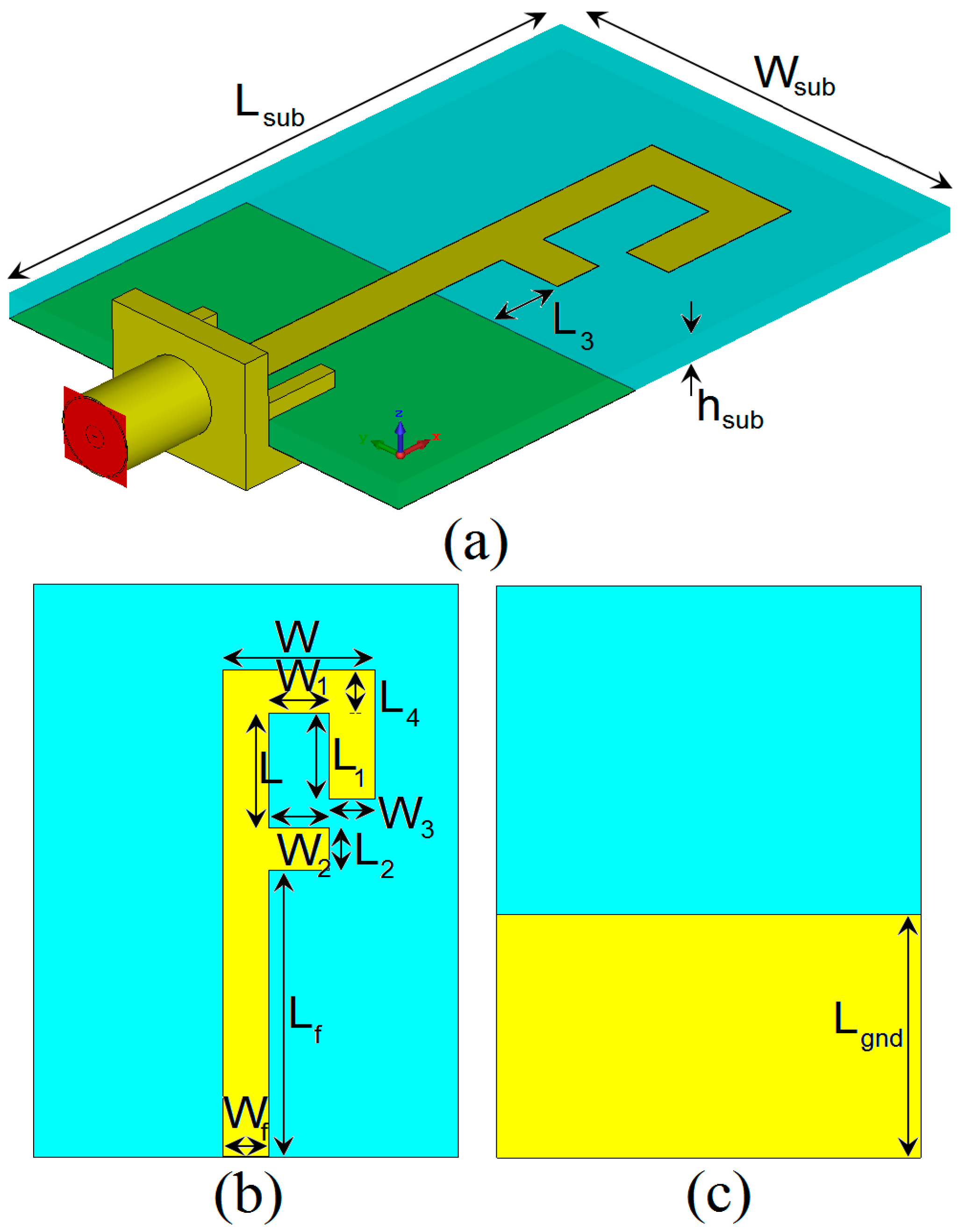
Configuration of the antenna is illustrated in Figure 1. It is printed on a low-cost FR-4 dielectric, whose relative permittivity, loss tangent, and thickness are 4.4, 0.025, and hsub = 1.6 mm, respectively. The FR4 dielectric combines good electrical features, price, and availability. Compared with other materials, FR4 material is sufficiently cheap and available in the market and has been widely used in antenna designing for frequencies less than 6 GHz. Moreover, FR-4 material is available in more thickness values than other ones, which gives more design flexibility. However, as the antenna operation frequency is increased, the permittivity of FR-4 varies and loss in the substrate increases [16]. Therefore, for ultra-high frequency designs, it is better to use materials prone to loss, such as Arlon, Roger, and others.
The radiation patch of the designed antenna is connected to a rectangular feed-line with Wf width and Lf length. The width of the microstrip feed-line is fixed at 3 mm. On the other side of the substrate, a conducting ground plane of Wsub width and Lgnd length is placed. The antenna is connected to a 50 Ω SMA connector for signal transmission. The parameter values for the antenna design are listed in Table 1.
3. Results and Discussions
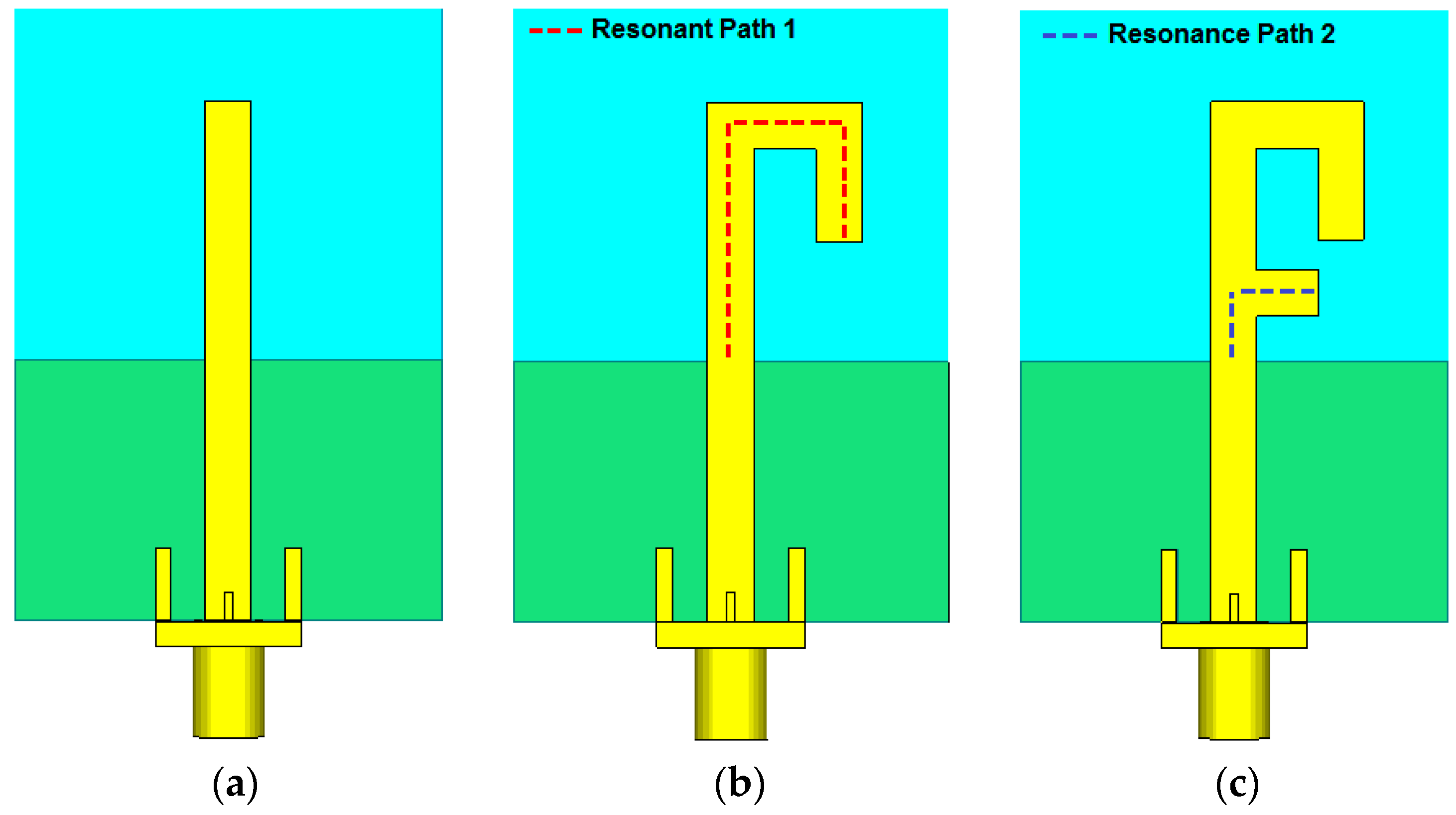
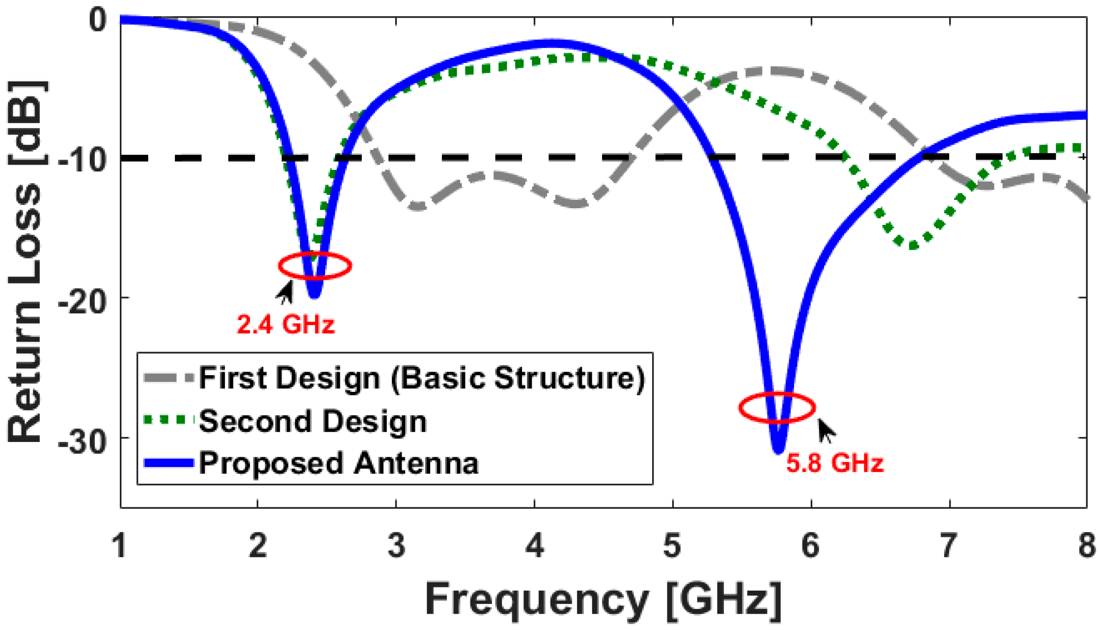
The motive behind the presented design is to achieve a dual-band characteristic for use in RFID applications. This has been achieved by using the presented antenna design with a modified radiation patch. Return loss characteristics of the rectangular monopole antenna (Figure 2a), the antenna with a Γ-shaped radiating patch (Figure 2b), and the antenna with a modified F-shaped radiator (Figure 2c) are illustrated compared in Figure 3.
It is observed that the lower frequency bandwidth (2.2–2.6 GHz) with a resonance at 2.6 GHz is affected by Γ-shaped structure, and the upper-frequency bandwidth (5.2–6.8 GHz), resonating at 5.8 GHz, is created and improved by adding a short rectangular strip, which modifies the radiation patch to the F-shaped structure. The optimized length Lresonance is set to resonate around 0.25λresonance, where Lresonance1 = L3 + L2 + L + L4 + (W − W3) +L1 and Lresonance2 = L3 + W2 + Wf/2 + L2. λresonance1 and λresonance2 correspond to the first and second resonance frequencies (2.4 GHz and 5.8 GHz), respectively.
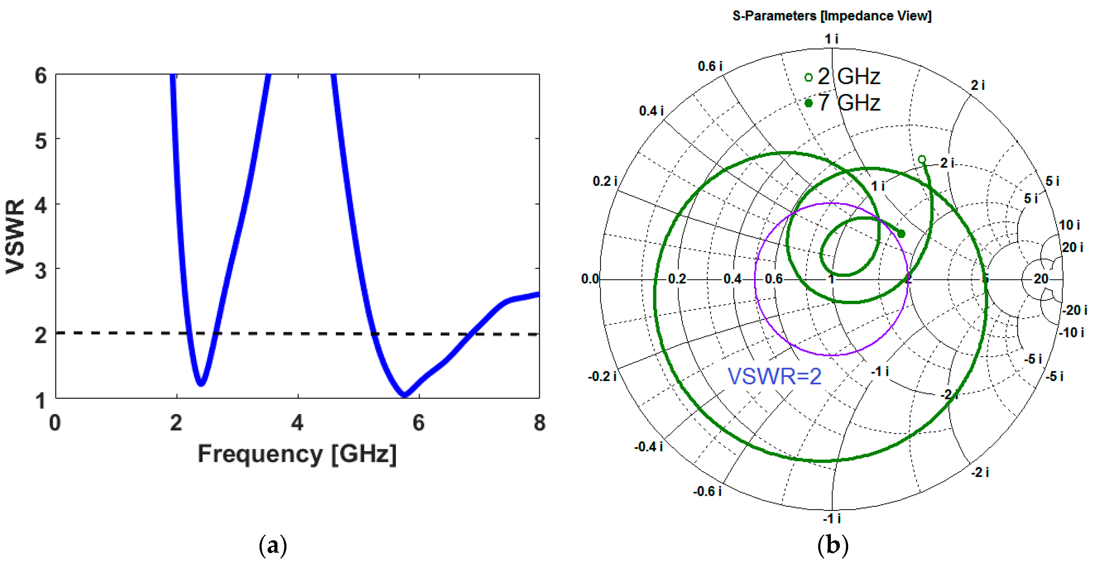
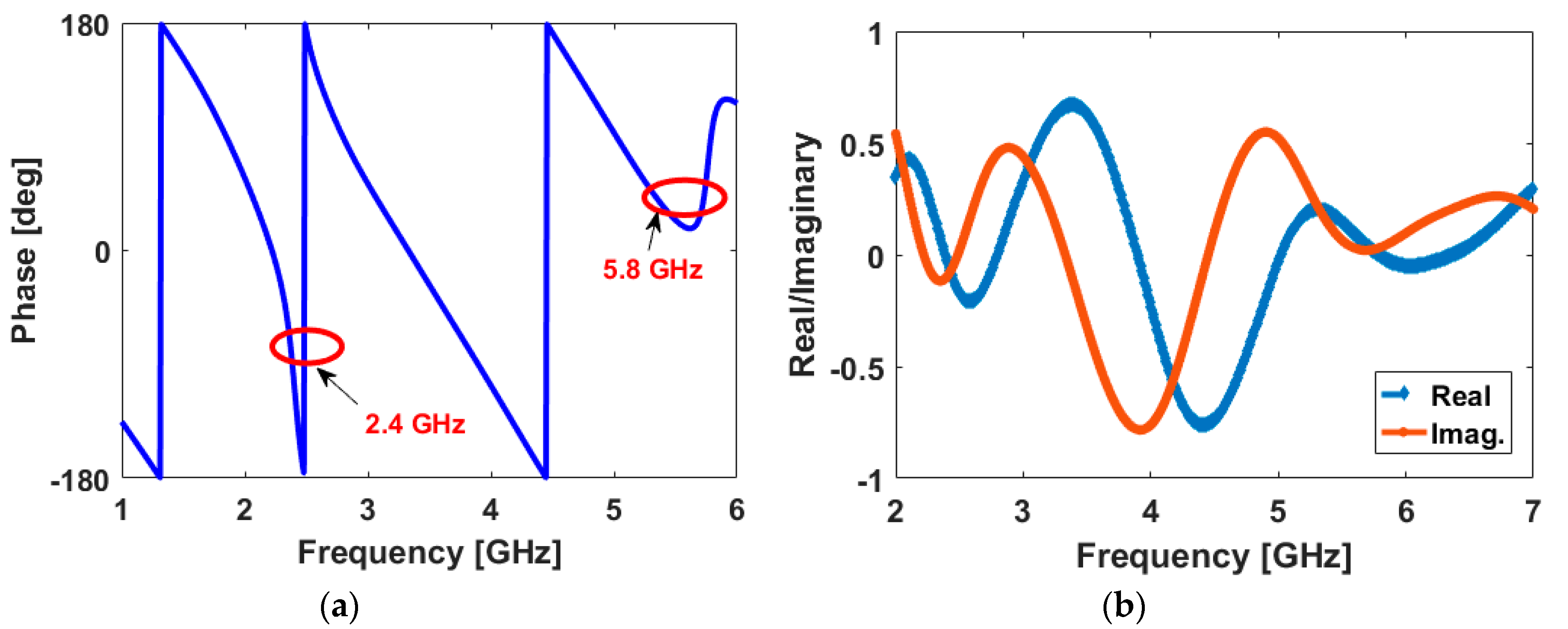
The voltage standing wave ratio (VSWR) and Smith-Chart results of the antenna are represented in Figure 4. It is seen that the antenna properly resonates at 2.4 and 5.8 GHz. As shown, it operates from 2.2 to 2.6 GHz (400 MHz impedance-bandwidth) and from 5.3 to 6.8 GHz (1500 MHz impedance-bandwidth). In addition, the reflected phase of the antenna S11 and its real and imaginary parts are illustrated in Figure 5, respectively. As seen, the effects of the resonances at 2.4/5.8 GHz are evident in the provided results.
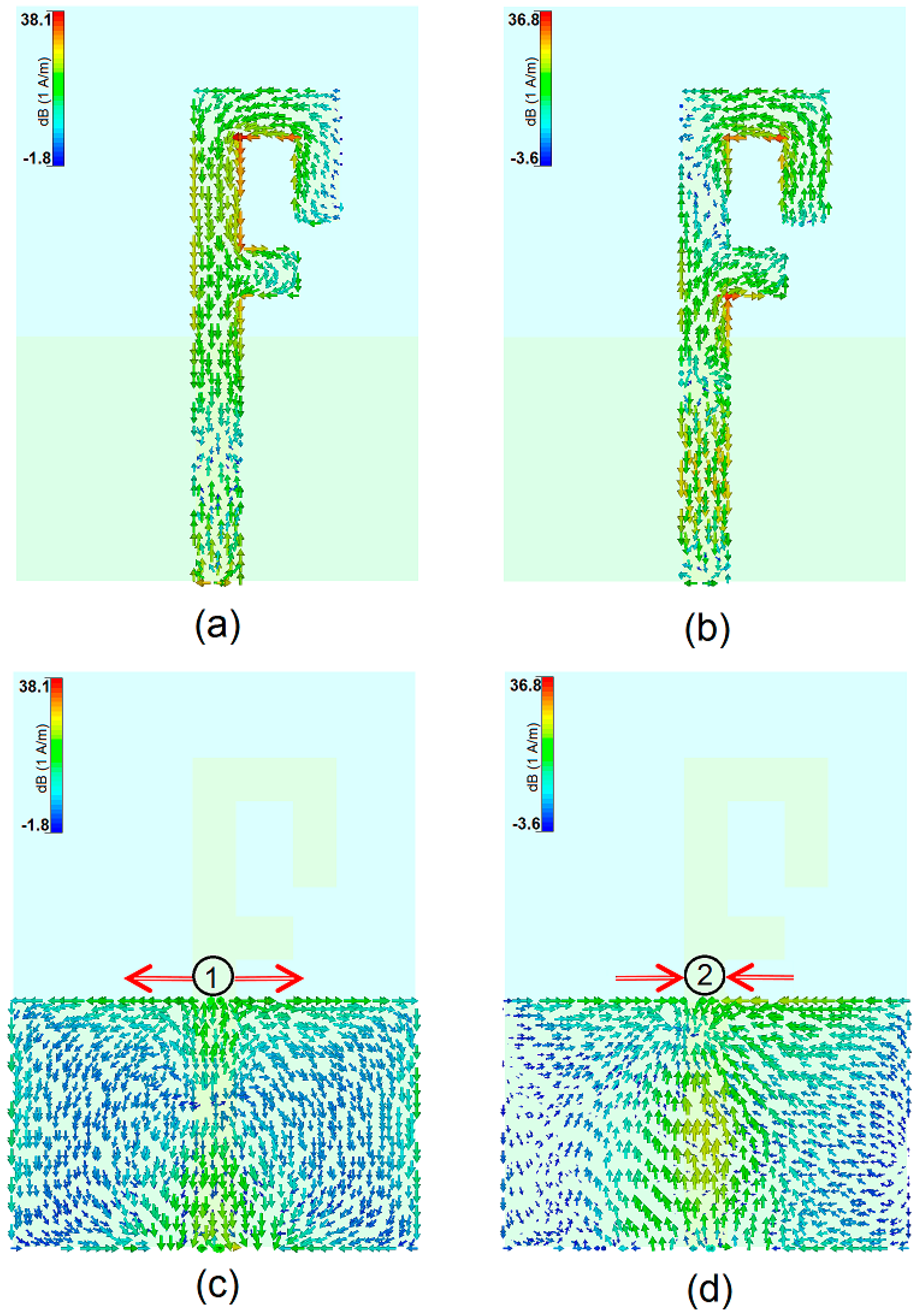
In order to further understand the principle of the dual-band characteristic, simulated surface current densities for the resonant frequencies on the radiation patch and the ground plane are illustrated in Figure 6. As seen in Figure 6a, at 2.4 GHz, the current flow contraries on the interior edge of the first resonator (the main arm of the modified F-shaped radiation patch). At 5.8 GHz, the current flows are highly dominated around the second arm of the radiation patch, as illustrated in Figure 6b. Figure 6c,d show the current distributions in the ground plane of the proposed design at the resonant frequencies: the current flow concentrates around the top edge of the ground plane. In addition, it is observed that at 5.8 GHz, the direction of current flows changes at the edges of the ground plane in comparison to that at the first resonance (2.4 GHz).
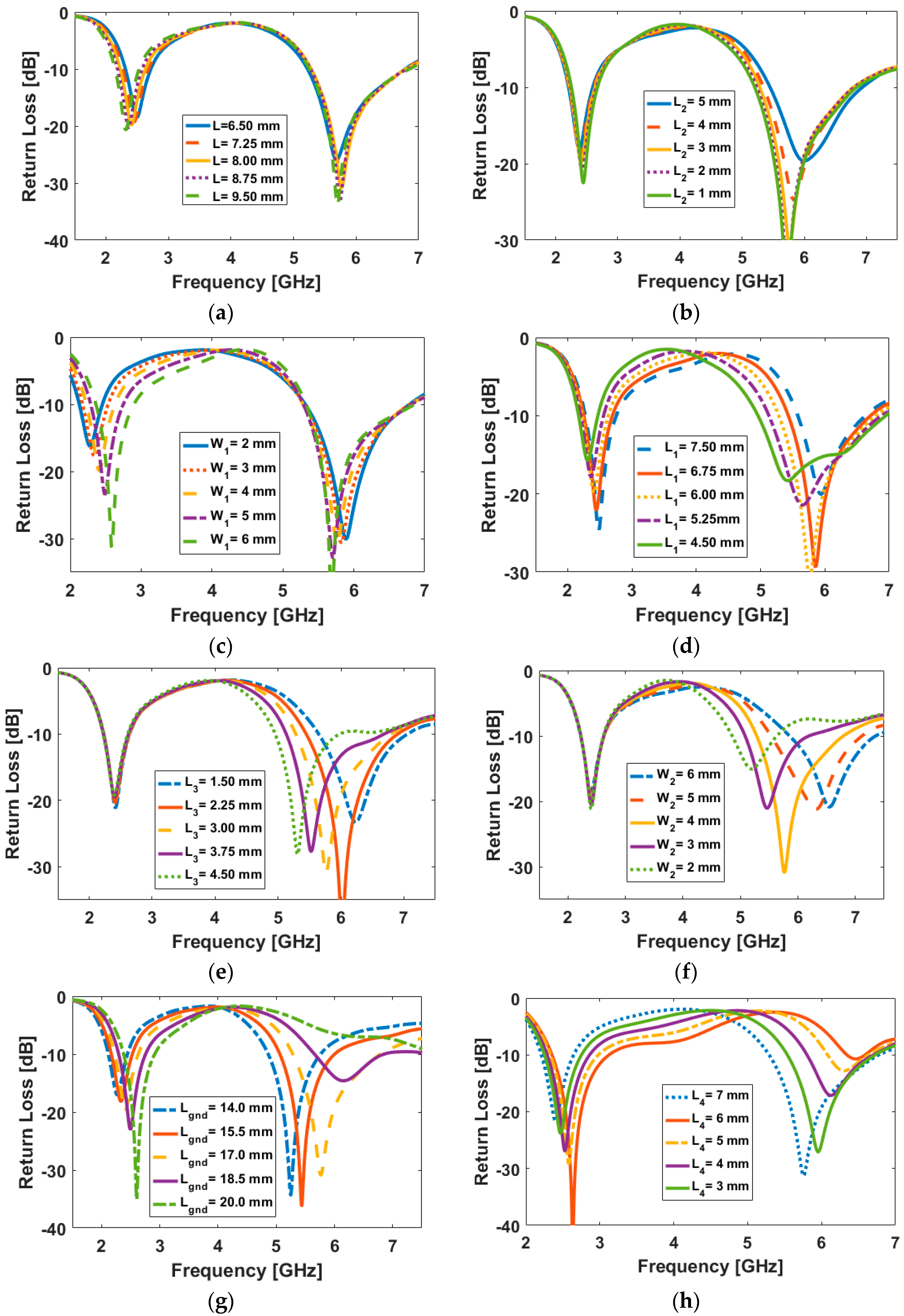
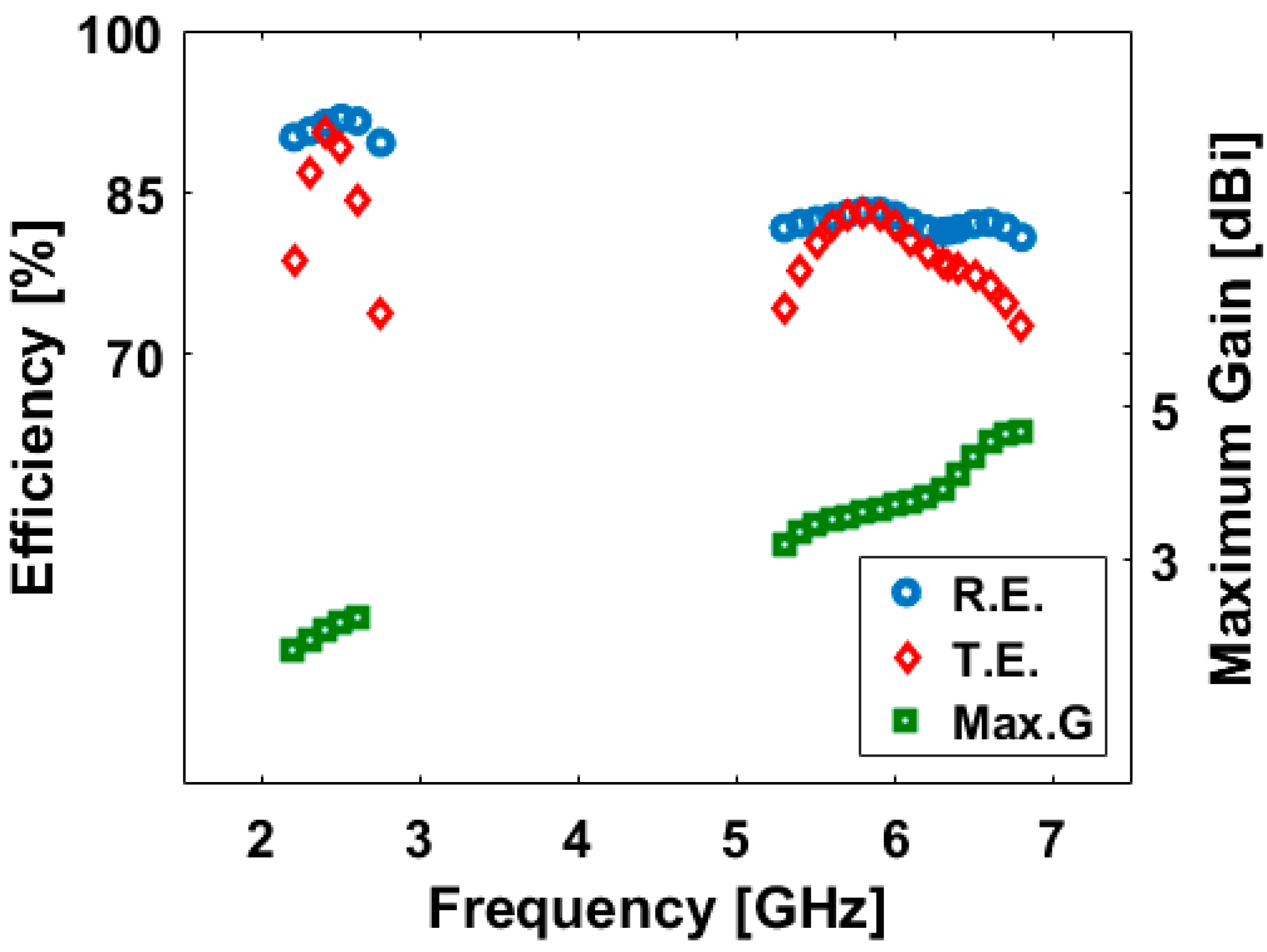
Results of varying fundamental design parameters, W1, W2, L, L1, L2, L3, L4, and Lgnd are shown in Figure 7a–h. Figure 7a,b shows the effects of L and L2 on the impedance matching; the operation frequency bands of the antenna are not affected significantly. In contrast, as shown in Figure 7c,d, the return loss characteristic of the antenna can be tuned at both of the resonant frequencies for different values of L1 and W1. Figure 7e,f illustrates the impact of different values for L3 and W2 on the antenna operation frequency; they have significant impacts on the second resonant frequency (5.8 GHz) with very little impact on the first resonant frequency (2.4 GHz). It is observed from Figure 7g,h that the isolation and impedance-matching characteristics of the antenna at both resonant frequencies are highly depended on values of Lgnd and L4. Figure 8 illustrates the antenna fundamental radiation characteristics over the operation bands. As shown, more than 75% radiation and total efficiencies (R.E. and T.E.) have been achieved at the frequency bands. More than 2 dBi and 4 dBi maximum gain levels are obtained for the antenna at 2.4 and 5.8 GHz, respectively.
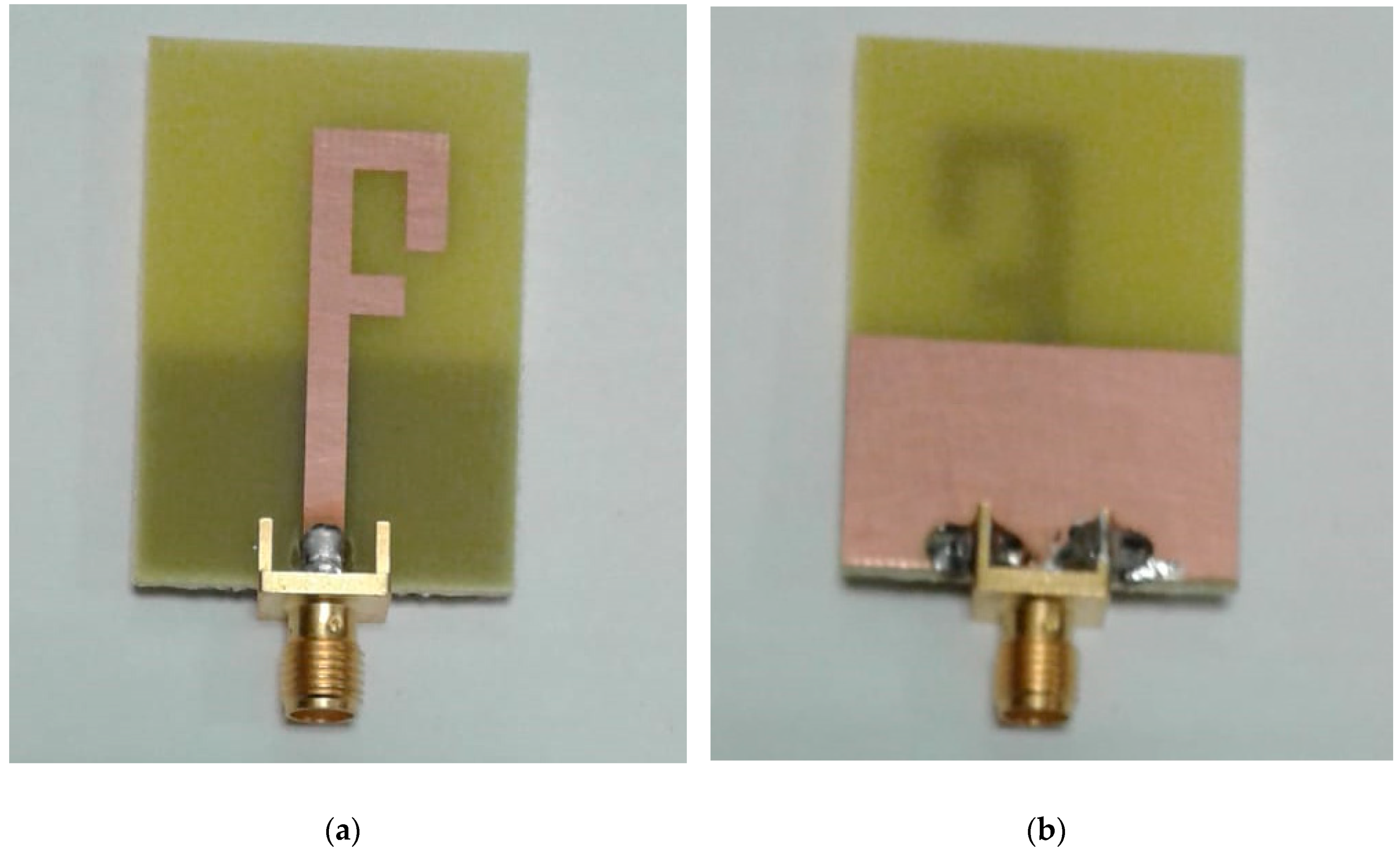
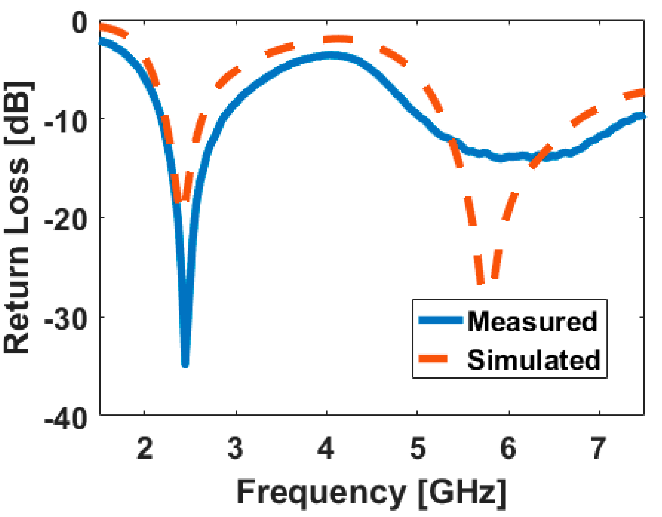
Top and bottom views for the prototype are illustrated in Figure 9. The antenna has been constructed on a low-cost FR4 dielectric substrate with an overall dimension of 40 × 28 × 1.6 mm3. The measured and simulated return loss characteristics of the antenna are represented in Figure 10. As can be observed, the antenna exhibits good return loss characteristic, covering 2.4/5.8 GHz resonant frequencies, which compared with the simulated result, the agreement is acceptable. However, there is a slight discrepancy between them which could be mostly due to possible errors in the prototype dimensions as well as the permittivity of the high-loss FR-4 substrate.
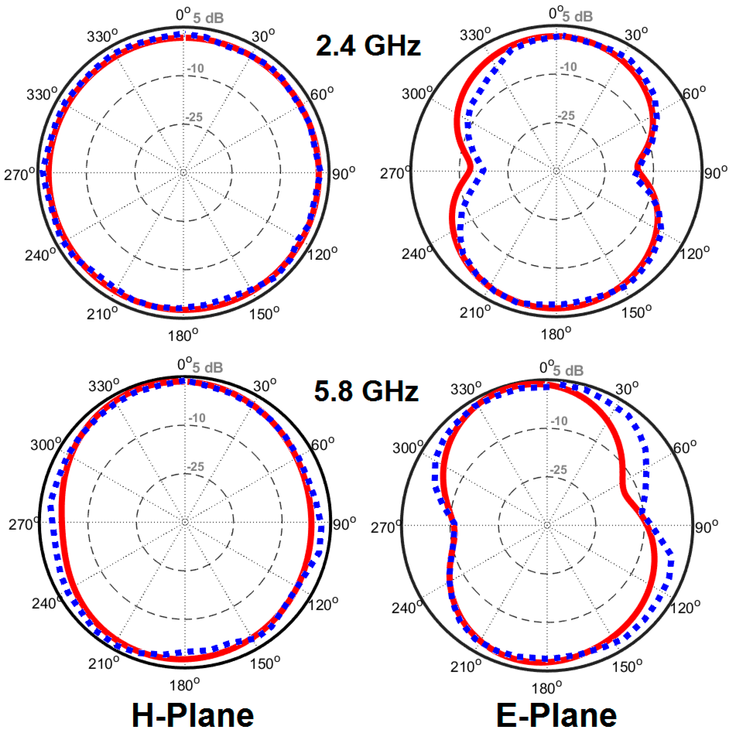
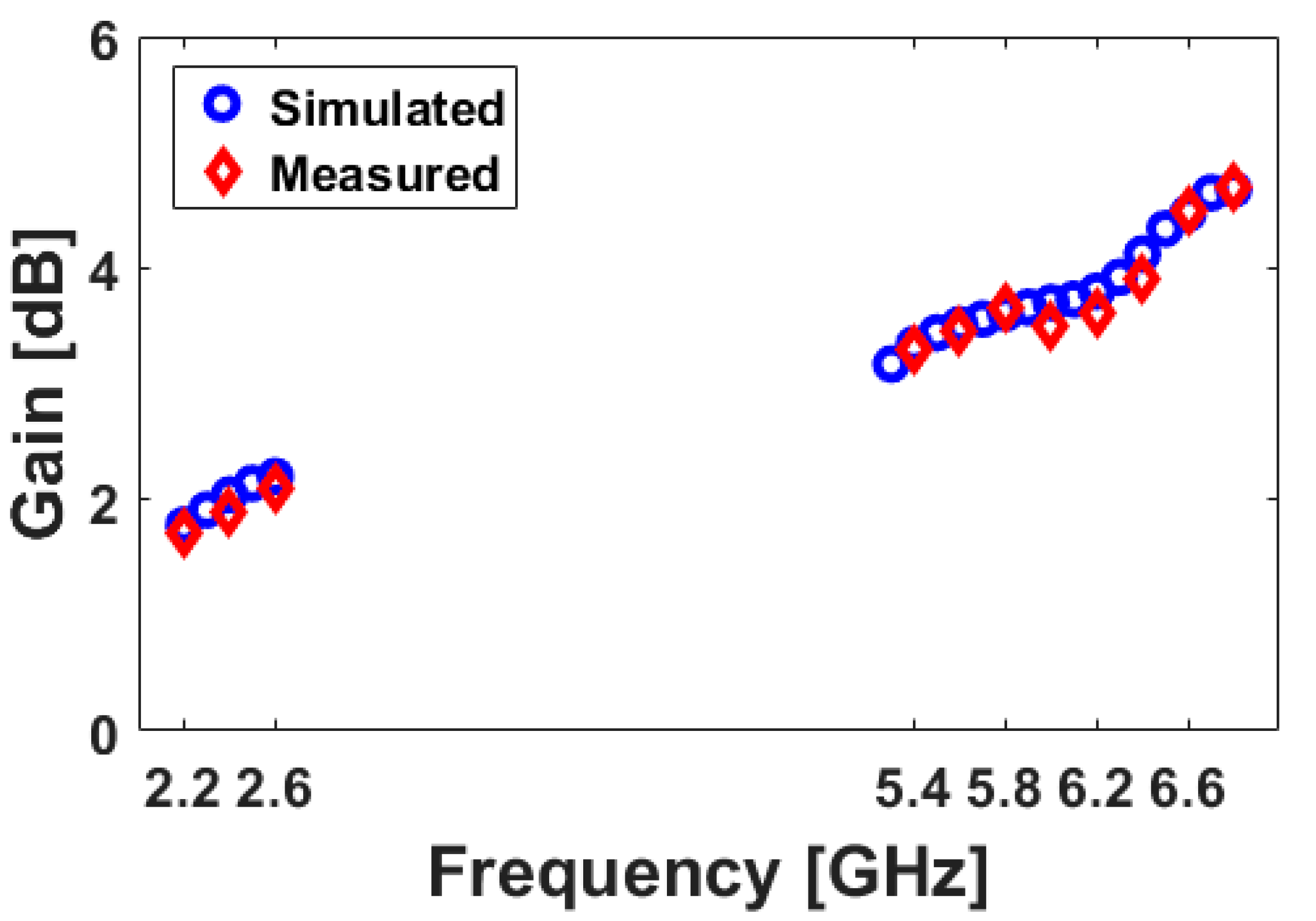
The simulated and measured 2D-polar radiation patterns of the antenna for H-plane and E-plane at 2.4 and 5.8 GHz are illustrated in Figure 11; the antenna provides omnidirectional radiation patterns in the H-plane, while 8-shaped radiation patterns in E-plane have been achieved for different resonant frequencies. The simulation and measurement results of the antenna gain versus its operation frequency are plotted in Figure 12; the antenna provides sufficient gain levels with more than 2 dB at 2.6 GHz and 3.5 dB at 5.8 GHz.
4. Conclusions
A design of dual-band antenna covering 2.4/5.8 GHz has been presented for RFID applications. To achieve the dual-band function, a monopole antenna with a radiation patch similar to F shape was designed and its properties were investigated. The impedance-bandwidth of the antenna spans from 2.2–2.6 GHz and 5.3–6.8 GHz, providing broad bandwidth and good radiation characteristics. The antenna provides omnidirectional radiation patterns with appropriate gain values at both of the operation bands. The antenna is simple and might be a suitable candidate for use in RFID systems.
Author Contributions
Conceptualization, N.O.P. and H.J.B.; methodology, N.O.P. and H.J.B.; software, N.O.P. and H.J.B.; validation, N.O.P., H.J.B., and R.A.A.-A.; formal analysis, N.O.P., H.J.B., and R.A.A.-A.; investigation, N.O.P., H.J.B., and R.A.A.-A.; resources, N.O.P., H.J.B., and R.A.A.-A.; data curation, N.O.P., H.J.B., and R.A.A.-A.; writing—original draft preparation, N.O.P., H.J.B., and J.M.N.; writing—review and editing, N.O.P., H.J.B., R.A.A.-A., and J.M.N.; visualization, N.O.P., H.J.B., R.A.A.-A., and J.M.N.
Funding
This project has received funding from the European Union’s Horizon 2020 research and innovation program under grant agreement H2020-MSCA-ITN-2016 SECRET-722424.
Acknowledgments
Authors wish to express their thanks to the support provided by the innovation program under grant agreement H2020-MSCA-ITN-2016 SECRET-722424.
Conflicts of Interest
The authors declare no conflict of interest.
References
- Finkenzeller, K. RFID Handbook: Radio-Frequency Identification Fundamentals and Applications, 2nd ed.; Wiley: New York, NY, USA, 2004. [Google Scholar]
- Chawla, V.; Ha, D.S. An overview of passive RFID. IEEE Commun. Mag. 2007, 45, 11–17. [Google Scholar] [CrossRef]
- Bell, M.S. RFID Technology and Applications; Cambridge University Press: London, UK, 2011; pp. 6–8. [Google Scholar]
- Siakavara, K.; Goudos, S.; Theopoulos, A.; Sahalos, J. Passive UHF RFID tags with specific printed antennas for dielectric and metallic objects applications. Radioengineering 2017, 26, 735–745. [Google Scholar] [CrossRef]
- Zeng, Y.; Chen, Z.N.; Qing, X.; Jin, J.-M. A directional, closely spaced zero-phase-shift-line loop array for UHF near-field RFID reader antennas. IEEE Trans. Antennas Propag. 2018, 66, 5639–5642. [Google Scholar] [CrossRef]
- Chang, L.; Wang, H.; Zhang, Z.; Li, Y.; Feng, Z. Compact single feed dual-mode antenna for active RFID tag application. IEEE Trans. Antennas Propag. 2015, 63, 5190–5194. [Google Scholar] [CrossRef]
- Liu, Q.; Shen, J.; Yin, J.; Liu, H.; Liu, Y. Compact 0.92/2.45-GH dual-band directional circularly polarized microstrip antenna for handheld RFID reader applications. IEEE Trans. Antennas Propag. 2015, 63, 3849–3856. [Google Scholar] [CrossRef]
- Wang, B.; Wang, W. A miniature tri-band RFID reader antenna with high gain for portable devices. Int. J. Microw. Wirel. Technol. 2017, 9, 1163–1167. [Google Scholar] [CrossRef]
- Ojaroudi, N. Design of microstrip antenna for 2.4/5.8 GHz RFID applications. In Proceedings of the German Microwave Conference, Aachen, Germany, 10–12 March 2014. [Google Scholar]
- Ojaroudi, M.; Ojaroudi, N. Compact H-ring antenna with dual-band operation for wireless sensors and RFID tag systems in ISM frequency bands. Microw. Opt. Technol. Lett. 2013, 55, 697–700. [Google Scholar] [CrossRef]
- Ojaroudi, M.; Ojaroudi, N. Dual-band coplanar waveguide-fed monopole antenna for 2.4/5.8 GHz radiofrequency identification applications. Microw. Opt. Technol. Lett. 2012, 54, 2426–2429. [Google Scholar] [CrossRef]
- Panda, J.R.; Kshetrimayum, R.S. A printed 2.4 GHz/5.8 GHz dualband monopole antenna for WLAN and RFID applications with a protruding stub in the ground plane. In Proceedings of the 2011 National Conference on Communications (NCC), Bengaluru, India, 28–30 January 2011; pp. 1–5. [Google Scholar]
- Kumar, A.; Deegwal, J.K.; Sharma, M.M. Design of multi-polarised quad-band planar antenna with parasitic multistubs for multiband wireless communication. IET Microw. Antennas Propag. 2018, 12, 718–726. [Google Scholar] [CrossRef]
- Ojaroudi, N.; Ojaroudi, M. A novel design of triple-band monopole antenna for multi-input multi-output communication. Microw. Opt. Technol. Lett. 2013, 55, 1258–1262. [Google Scholar] [CrossRef]
- Yang, W.; Zhou, J.; Yu, Z.; Li, L. Single-fed low profile broadband circularly polarized stack.patch antenna. IEEE Trans. Antennas Propag. 2014, 62, 5406–5410. [Google Scholar] [CrossRef]
- Khan, A.; Nemar, R. Analysis of five different dielectric substrateson microstrip patch antenna. Int. J. Comput. Appl. 2012, 18, 6–12. [Google Scholar]
Figure 1.
(a) Side, (b) top, and (c) bottom views of the antenna.

Figure 2.
Different structures of the antenna, (a) rectangular-shaped, (b) Γ-shaped, and (c) F-shaped.
Figure 2.
Different structures of the antenna, (a) rectangular-shaped, (b) Γ-shaped, and (c) F-shaped.

Figure 3.
The return losses for the structures shown in Figure 2.
Figure 3.
The return losses for the structures shown in Figure 2.

Figure 4.
(a) VSWR and (b) Smith-Chart result of the antenna.

Figure 5.
(a) Phase, (b) real and imaginary parts of the antenna.

Figure 6.
Current distributions at (a) 2.4 GHz and (b) 5.8 GHz on the radiation patch, and (c) 2.4 GHz and (d) 5.8 GHz in the ground plane.
Figure 6.
Current distributions at (a) 2.4 GHz and (b) 5.8 GHz on the radiation patch, and (c) 2.4 GHz and (d) 5.8 GHz in the ground plane.

Figure 7.
Return loss results for different values of (a) L, (b) L2, (c) W1, (d) L1, (e) L3, (f) W2, (g) Lgnd, and (h) L4.
Figure 7.
Return loss results for different values of (a) L, (b) L2, (c) W1, (d) L1, (e) L3, (f) W2, (g) Lgnd, and (h) L4.

Figure 8.
The antenna fundamental radiation characteristics.

Figure 9.
Fabricated antenna, (a) top and (b) bottom views.

Figure 10.
Measured and simulated return losses of the antenna.

Figure 11.
Simulated and measured 2D-polar radiation patterns.

Figure 12.
Measured and simulated gain results of the antenna.


Table 1.
Parameter values of the antenna design.
| Parameter | Value (mm) | Parameter | Value (mm) | Parameter | Value (mm) |
|---|---|---|---|---|---|
| WSub | 28 | Lsub | 40 | hsub | 1.6 |
| Wf | 3 | Lf | 20 | W | 10 |
| W1 | 4 | W2 | 4 | L | 8 |
| L1 | 6 | L2 | 3 | L3 | 3 |
| L4 | 3 | Lgnd | 17 | W3 | 3 |
© 2019 by the authors. Licensee MDPI, Basel, Switzerland. This article is an open access article distributed under the terms and conditions of the Creative Commons Attribution (CC BY) license (http://creativecommons.org/licenses/by/4.0/).
Share and Cite
MDPI and ACS Style
Ojaroudi Parchin, N.; Jahanbakhsh Basherlou, H.; Abd-Alhameed, R.A.; Noras, J.M. Dual-Band Monopole Antenna for RFID Applications. Future Internet 2019, 11, 31. https://doi.org/10.3390/fi11020031
AMA Style
Ojaroudi Parchin N, Jahanbakhsh Basherlou H, Abd-Alhameed RA, Noras JM. Dual-Band Monopole Antenna for RFID Applications. Future Internet. 2019; 11(2):31. https://doi.org/10.3390/fi11020031
Chicago/Turabian StyleOjaroudi Parchin, Naser, Haleh Jahanbakhsh Basherlou, Raed A. Abd-Alhameed, and James M. Noras. 2019. "Dual-Band Monopole Antenna for RFID Applications" Future Internet 11, no. 2: 31. https://doi.org/10.3390/fi11020031
Note that from the first issue of 2016, this journal uses article numbers instead of page numbers. See further details here.